

Page 1

Document Type: Service Manual
Version 1.2 10272017
SERVICE MANUAL
Single Zone Cooler
MODEL:
AFR151SSOD, AFR151SS, ABR151SG, AWC151SZ, ABR241SG,
AWC241SZ, AFR241SS, AFR241SSOD, AWC241TSZ, AWC241FD
CAUTION: READ ALL SAFETY PRECAUTIONS IN THIS
MANUAL BEFORE SERVICING THE UNIT
EdgeStar, 8606 Wall St, Suite 1800, Austin, TX 78754
support.edgestar.com • service@edgestar.com • edgestar.com
*Warranty service should be performed by an authorized service representative only.
Page 2

CONTENTS
- 2 -
SAFETY PRECAUTIONS .............................................................................................................................................................2
PARTS IDENTIFICATION .......................................................................................................................................................3-12
DISASSEMBLY......................................................................................................................................................................12-19
DOOR .....................................................................................................................................................................................12
GLASS SHELVES..................................................................................................................................................................13
WIRES SHELVES..............................................................................................................................................................13-14
TOP LAMP………… ..............................................................................................................................................................14
BROADSIDE LAMP...............................................................................................................................................................14
COLD CATALYST SYSTEM......................................................................................................................................................14
DISPLAY BOARD BOARD & CONTROL BOARD................................................................................................................15
POWER BOARD & TRANSFORMER ....................................................................................................................................15
SENSOR & FAN................................................................................................................................................................16-18
COMPRESSOR PTC STARTER & OVERLOAD PROTECTOR......................................…………… ……………….…….18
TROUBLESHOOTING.........................................................................................................................................................20-23
COMPRESSOR COMPONENTS ..........................................................................................................................................20
ANOTHER ELECTRIC COMPONENT ..................................................................................................................................21
SERVICE DIAGNOSIS CHART.............................................................................................................................................22
REFRIGERATING CYCLE ....................................................................................................................................................23
DESCRIPTION OF PCB .........................................................................................................................................................24
SAFETY PRECAUTIONS
Please read the followings before servicing your appliance.
1. Check if an electric leakage occurs in the set.
2. To prevent electric shock, unplug prior to servicing.
3. In case of testing with power on, wear rubber gloves
to prevent electric shock.
4. If you use any appliances, check regular current,
voltage and capacity.
5. Don't touch metal products in cold freezer with wet
hand. It may cause frostbite.
6. Prevent water flowing to electric elements in
mechanical parts.
7. When sloping the set, remove any materials on the
set, especially thin plate type. (ex.: glass shelf or
books.)
8. When servicing evaporator part, wear cotton gloves
without fail. It is to prevent wound by sharp fin of
evaporator.
9. Leave a breakage of refrigerating cycle to a heavy
service center. The gas in cycle inside may soil
ambient air.
Page 3

- 3 -
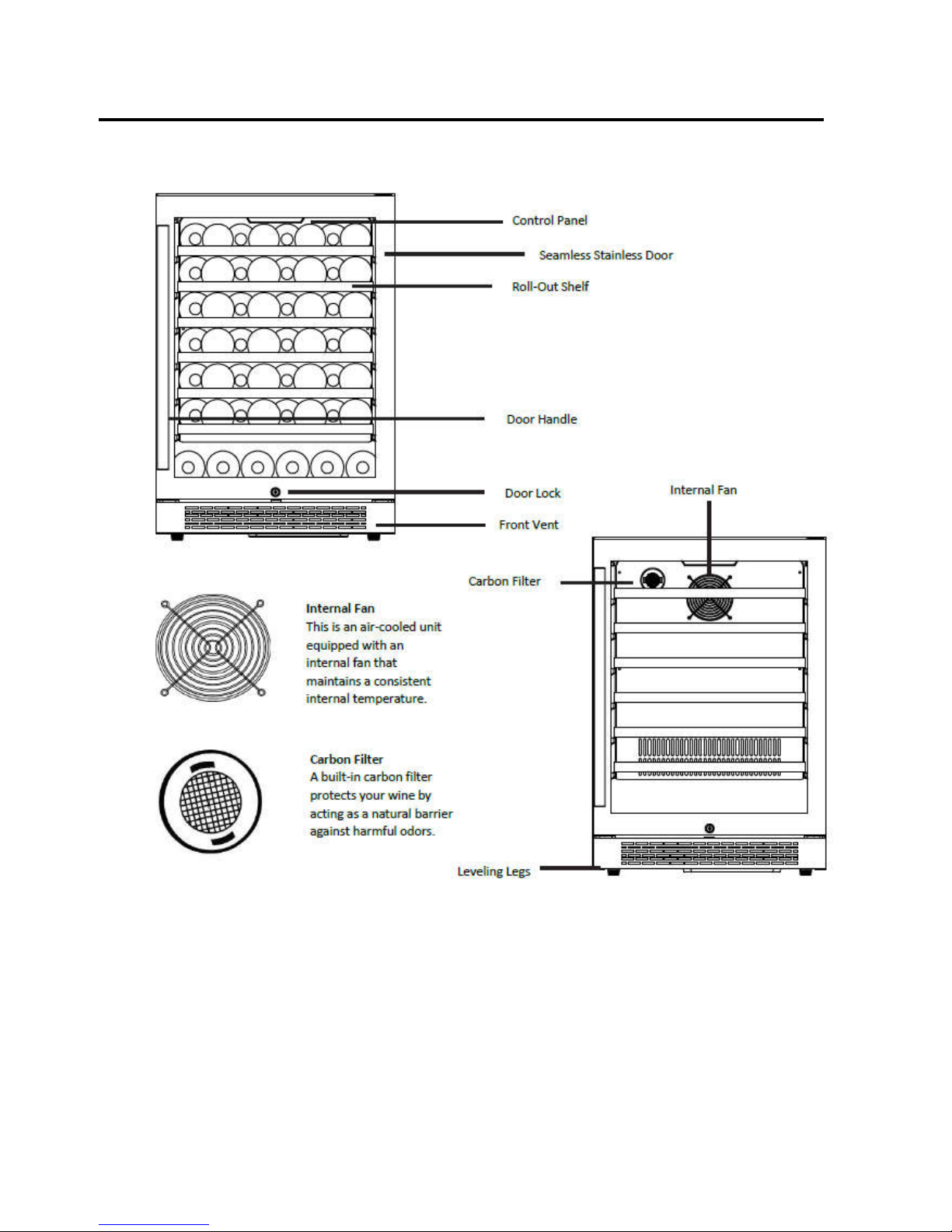
2. PARTS IDENTIFICATION
Model:AFR151SSOD
Models:CWR361FD
Page 4

- 4 -
2. PARTS IDENTIFICATION
Models:AFR151SS
Models:CWF340DZ
Page 5

- 5 -
2. PARTS IDENTIFICATION
Models:ABR151SG
Page 6

- 6 -
2. PARTS IDENTIFICATION
Models:AWC151SZ
Page 7

- 7 -
2. PARTS IDENTIFICATION
Models:ABR241SG
Door
Control Panel
Shelf
Door Lock
Page 8
- 8 -
2. PARTS IDENTIFICATION
Models:AWC241SZ
Front Vent
Page 9

- 9 -
2. PARTS IDENTIFICATION
Models:AFR241SS
Page 10

- 10 -
2. PARTS IDENTIFICATION
Models:AFR241SSOD
Page 11

- 11 -
2. PARTS IDENTIFICATION
Models:AWC241TSZ
Page 12

- 12 -
2. PARTS IDENTIFICATION
Models:AWC241FD
Page 13

- 13 -
3. DISASSEMBLY
3-1 DOOR
(Models:AFR151SSOD, AFR151SS, ABR151SG,
AWC151SZ, , ABR241SG, AWC241SZ, AFR241SS,
AFR241SSOD, AWC241FD
Loosen 2 bolts securing the lower door axis to the lower
hinge to remove the door. (Figure 1)
Lower Doo
r Axis
BOLT
Figure 1
(Models:AWC241TSZ)
Loosen 2 bolts securing the lower door axis to the lower
hinge to remove the door. (Figure 2)
Figure2
3-2 GLASS SHELVES
(Models:AFR151SSOD, AFR151SS, ABR151SG,
ABR241SG)
Open the door completely.
Lift either the left or right side of the shelf creating a 45◦
angle from its original position. Make sure not to lift either
side of the shelf too hard as it may come in contact with the
inner wall mount.
Pull the shelf outward until it is removed from the inner
compartment. You may encounter some resistance from
the shelf guard rail. (figure 3)
Figure 3
(Model:AFR241SS, AFR241SSOD)
1. Open the door c
ompletely.
2. Remove all of the contents loaded on the shelf, if
applicable.
3. With the shelf pushed all the way to the rear of the
unit, position the cutouts in the left & right sides of the
shelves
under the plastic posts on each side of the shelf track.
4. Push down on the front of the shelf while lifting up
on the rear of the shelf (picture a seesawing motion)
until the
shelf passes over the plastic posts.
5. Pull the shelf forward until it is completely removed
from the inner compartment.
(figure 5)
Figure5
3-3 WIRES SHELVES:
(Model:AWC151SZ, ,AWC241SZ)
you must pull the shelves approximately 1/3 out of the rail
compartment.
To remove the shelves out of the rail, pull each shelf
approximately 1/3 out. Use a long flat screwdriver to press
down the right plastic notch as shown in Figure 3 and at the
same time lift the left plastic notch as shown in Figure 4.
Then proceed to pull out the shelf slowly. (figure 4)
Figure 4
Metal guide post
Page 14

- 14 -
3. DISASSEMBLY
(Model:AWC241TSZ)
1. Open the door c
ompletely.
2. Remove all of the contents loaded on the shelf, if
applicable.
3. Line up the shelf notches with the rail posts as
indicated below. This will require you to hold on to both
rails as you
move the shelf to line up the posts with the notches on
both sides of the shelf.
4. Evenly lift the shelf up and then pull the shelf out.
(Figure 6)
Figure6
Open the door completely.
If necessary, make sure you remove all the contents sitting
on the shelf..
Pull the shelf forward until the notch aligns with the plastic
post on each side of the shelf track.
Lift the shelf until both notches pass through the posts.
Continue to pull the shelf forward until it is completely removed
from the inner compartment. (Figure 7)
Figure7
3-6 TOP LAMP
(Models:AFR151SSOD, AFR151SS, ABR151SG,
AWC151SZ, , ABR241SG, AWC241SZ, AFR241SS,
AFR241SSOD, AWC241TSZ, AWC241FD.)
1.
1 Loosen four screws. (figure 8)
Figure 8
screw
2. Unplug the led light connector. (figure 9)
Figure 9
3. Loosen four screws. (figure 10)
Screw
Figure 10
4.
Pull out the LED light. The LED light is like below.
(figure 11)
Figure 8
Figure 11
3-7 BROADSIDE LAMP
(Models:AFR151SSOD, AFR151SS, ABR151SG,
AWC151SZ, , ABR241SG, AWC241SZ, AFR241SS,
AFR241SSOD, AWC241TSZ, AWC241FD.)
1.
1Pull the lamp cover.
2.
Separate the claw attached to the LED light. Separate the
lead wire housing. (figure 12)
Figure 12
3. The LED light is pictured below. (figure 13)
Figure 13
connecto
r
Page 15

- 15 -
3. DISASSEMBLY
3-8 DISPLAY BOARD & CONTROL BOARD
(Models:AFR151SSOD, AFR151SS, ABR151SG,
AWC151SZ, , ABR241SG, AWC241SZ, AFR241SS,
AFR241SSOD, AWC241TSZ, AWC241FD)
1. Loosen four screws.
2. Pull out the electrical box.
3.
Unplug all cable connectors. (figure 14)
screw
Figure 14
4. Loosen four screws. (figure 15)
screw
Figure 15
5. The control board is pictured below. (figure 16)
Figure 16
6. Remove the display cover. Pull out the display board support
and find out the display board inside it. (figure 17)
Figure 17
7. The display board is like below. (figure 18)
Figure 18
3-9 POWER BOARD & TRANSFORMER
(Models: ABR241SG, AWC241SZ, AFR241SS,
AFR241SSOD, AWC241TSZ, AWC241FD)
1. Loosen three screws. (figure 19)
Figure 19
2. The power board & transformer are like below. (figure 20)
Figure 20
Page 16

- 16 -
3. DISASSEMBLY
(Models:AFR151SSOD, AFR151SS, ABR151SG,
AWC151SZ
1. Loosen three screws. (figure 21)
Figure 21
2. The power board & transformer are like below. (figure 22)
Figure 22
3-10 SENSOR & FAN
(Models:AFR151SSOD, AFR151SS,)
1. Remove the screws on both sides of air duct board.. Pull
out the air duct board cover. (figure 23)
Carbon Filter
fan
Screw
Sensor
Figure 23
Remove the cover
screws
(Models:,ABR151SG, AWC151SZ)
1.1 Loosen six screws. Pull out the rear air duct cover.
(figure 24)
Carbon Filter
fan
Screw
Sensor
Figure 24
2.
Loosen 1 screw. You can replace the sensor & fan.
(figure 25)
wire housing
screw
evaporator
defrost
sensor
Figure 43
Figure 25
Page 17

- 17 -
3. DISASSEMBLY
(Models: ABR241SG, AWC241SZ )
1. Loosen six screws. Pull out the rear air duct cover.
(figure 26)
Carbon Filter
Fan
Screw
cold catalyst
Figure 26
2.
Loosen 1 screw. You can replace the sensor & fan.
(figure 27)
wire housing
screw
evaporator
sensor
Figure 27
(Models:AFR241SS, AFR241SSOD)
1. Loosen screws. Pull out the rear air duct cover.
(figure 28)
Carbon Filter
fan
t
sensor
screw
Figure 28
2.
Loosen 1 screw to replace the sensor & fan.
(figure 29)
wire housing
screw
evaporator
defrost
sensor
Figure 29
(Models:AWC241TSZ)
1、 Loosen screws. Pull out the rear air duct cover.
(figure 30)
Carbon Filter
sensor
fan
screw
Figure30
2、
Loosen 1 screw to replace the sensor & fan.
3、
(figure 31)
wire housing
screw
evaporator
defrost
sensor
Figure 31
Page 18

- 18 -
3. DISASSEMBLY
(Models:AWC241FD)
4、 Loosen screws. Pull out the rear air duct cover.
(figure 32)
Carbon Filter
fan
t
sensor
screw
Figure 32
5、
Loosen screw. You can replace the sensor & fan.
(figure 33)
wire housing
screw
Heater r
evaporator
Figure 33
3-11 COMPRESSOR PTC STARTER & OVERLOAD
PROTECTOR
(Models:AFR151SSOD, AFR151SS,ABR151SG,
AWC151SZ, ABR241SG, AWC241SZ,AFR241SS,
AFR241SSOD)
1. Open the box near compressor, the starter and overload
protector are located inside. (figure 34)
Figure 34
2. Dismantle the compressor PTC starter and overload
protector. (figure 35)
Figure 35
3. The compressor PTC starter and overload protector is like
below. (figure 36)
Figure 36
(Models:AWC241FD)
1、 Open the box near compressor, The starter and overload
protector are located inside. (figure 37)
Figure 37
Page 19

- 19 -
3. DISASSEMBLY
2、 Dismantle the compressor PTC starter and overload
protector. (figure 38)
Figure 38
3. The compressor PTC starter and overload protector is
pictured below. (figure 39)
Figure 39
(Models:AWC241TSZ)
1、Open the box near compressor. The starter and overload
protector are located inside. (figure 40)
Figure 40
2、 Remove the compressor junction box. (figure 41)
Figure 41
3、 The compressor PTC starter and overload protector is
pictured below. (figure 42)
Figure 54
Figure 42
Page 20

- 20 -
3. DISASSEMBLY
1
4-1 COMPRESSOR
COMPONENTS
Check the
resistance of
Motor
Compressor.
2
Check the
resistance of
PTC-Starter.
Check the resistance
among M-C, S-C and
M-S in Motor
Compressor.
Is it normal?
Check the resistance
of two terminals in
PTC-Starter.
Is it normal?
YES
NO
Replace Compressor.
YES
NO
2
2 3
3
Replace
PTC-Starter.
3
Check OLP.
Check if applying
a regular OLP.
NO
Replace OLP.
Page 21

- 21 -
4. TROUBLESHOOTING
Check if current flows to the
following components.
Cause.
a. Starting devices
Shorted or broken.
b. OLP
Poor contacting
or shorted.
c. Compressor coil Coil shorted.
d. Circuit Parts
Poor contacting
or shorted.
4-2 ANOTHER ELECT
RIC COMPONENTS
▼ Cooling is impossible
Compressor
doesn't run.
Replace
each component.
Running state of
Compressor is poor.
Check a starting
voltage.
Low voltage. Raise the voltage.
Check if current flows
to starting devices.
Poor contacting
and broken.
Replace
each component.
Check current flowing
in coil of
Compressor.
Shorted.
Check capacity of OLP.
Lack of capacity.
The items described
above are normal.
Coil of motor
Compressor.
Replace
the compressor.
▼ Cooling ability is poor
Fan motor
doesn't run.
Check Control PCB
Check current flowing
in the Fan Motor.
Poor contacting.
Coil is shorted.
Replace
each component.
Much frost are sticked
to the EVAPORATOR.
Check current flowing
of the following
components.
• Def. Sensor
Shorted.
Replace
each component.
Page 22

- 22 -
4. TROUBLESHOOTING
4-3 SERVICE DIAGNOSIS CHART
Problem
Possible Cause
Appliance d
oes not operate.
Not plugged in.
The appliance is turned off.
The circuit breaker tripped or a blown fuse.
Appliance is n
ot cold enough.
Check the tem
perature control setting. External
environment may require a higher
setting.
The door is opened too often.
The door is not closed completely.
The door gasket does not seal properly.
Turns on and off frequen
tly.
The room tempe
rature is hotter than normal.
A large amount of contents has been added to the wine chiller.
The door is opened too often.
The door is not closed completely.
The temperature control is not set correctly. The door
gasket does not seal properly.
The light does
not work.
Not plugged
in.
The circuit breaker tripped or a blown fuse. The bulb has
burned out.
The light button is “OFF”.
Energy conservati
on button is on.
Vibrations.
Check to assure that the appliance is level.
The appliance seems to make too much noise.
The rattling noise may come from the flow of the refrigerant,
which is normal.
As each cycle ends, you may hear gurgling
sounds caused by the flow of refrigerant in your refrigeration
appliance.
Contraction and expansion of the inside walls may cause
popping and crackling noises.
The appliance is not level.
The door will not close properly.
The appliance is not level.
The door was reversed and not properly installed. The gasket is
dirty.
The shelves are out of position.
Display error code “E1”
The air sensor has an open circui
t. Connection to main control
PCB is
with white color wires. Check the circuit, if it is normal,
the sensor may need to be replaced.
Display error code “E2”
The air sensor has a short circuit. Connection to main control
PCB is with white color wires. Check the circuit, if it is normal,
the sensor may need to be replaced.
Display error code “E3”.
The defrost sensor has an open circuit. Connection to main
c
ontrol PCB
is with red color wires. Check the circuit, if it is
normal, the sensor may need to be replaced.
Display error code “E4”.
The defrost sensor has a short circuit. Connection to main
c
ontrol PCB
is with red color wires. Check the circuit, if it is
normal, the sensor may need to be replaced.
Page 23

- 23 -
4. TROUBLESHOOTING
4-4 REFRIGERATING C
YCLE
▼ Troubleshooting Chart
LEAKAGE
PA R TIAL
LEAKAGE
Low owing sound of
Refrigerant is heard and
frost forms
A little high more than
ambient room
temperature.
WHOLE
LEAKAGE
Flowing sound of Refrigerant
is not heard and frost isn't
formed.
CLOG
IN CAPILLARY
Flowing sound of Refrigerant
is heard and frost forms
A little high more than
ambient room
temperature.
A little high more than
ambient room
temperature.
A little high more than
ambient room
temperature.
Flowing sound of Refrigerant
is not heard and frost isn't
formed.
YES
No frost or forms
in inlet only
Faulty
Normal amount
Inject Refrigerant to
Observe the discharging
amount of Refrigerant.
No or not much
NO
YES
Compressor.
Compressor and check
cooling operation.
Check Compressor
Clogged or restricted
Normal formed
frost in Evaporator
Find and Repair Leak
Appliance does
not get cold
enough
Appliance does
not get cold at all
Does compressor
turn on?
Is gas leak detected?
Observe refrigerant disharging point. Oil dishcharge/stain is often best indicator. indicator. Use bubbles to locate hole in line,
evaporator or condensor.
No cooling
Is oil leak detected?
• No discharging of refrigerant
• The capillary tube is faulty.
• The lter dryer is faulty.
• The condensor is faulty.
• The evaporator is faulty.
• No discharging of refrigerant
• A little refrigerant discharges
• Normal cooling is possible when
charging refrigerant of regular amount
stated on specication plate / rating
label.
• A little refrigerant discharges
• Normal cooling is possible when
charging refrigerant of regular amount
stated on specication plate / rating
label.
Does frost form on
the evaporator?
Appliance does
not get cold
enough
PARTIAL
RESTRICTION
CAUSE STATE OF UNIT STATE OF EVAPORATOR TEMPERATURE
OF COMPRESSOR
COMMENTS
WHOLE
RESTRICTION
Appliance does
not get cold
NO
Page 24

- 24 -
5.
DESCR
IPTION
OF PCB
(Models:AFR151SSOD / AFR151SS / ABR151SG / AWC151SZ / ABR241SG AWC241SZ AFR241SS AFR241SSOD
AWC241TSZ)
Figure 55
(Models:AWC241FD)
Figure 57
Page 25

DATE REVISION NOTES:
9/22/2017 Initial Document
10/16/2017 Minor text edits
10/27/2017 Minor text edits
EdgeStar, 8606 Wall St, Suite 1800, Austin, TX 78754
support.edgestar.com • service@edgestar.com • edgestar.com
*Warranty service should be performed by an authorized service representative only.
 Loading...