

Page 1
1718 W. Fullerton Ave
Chicago, IL 60614
Tel: 773-770-1195
Fax: 773-935-5613
www.edgelighting.com
© 2009 Edge Lighting. All Rights Reserved.
info@edgelighting.com
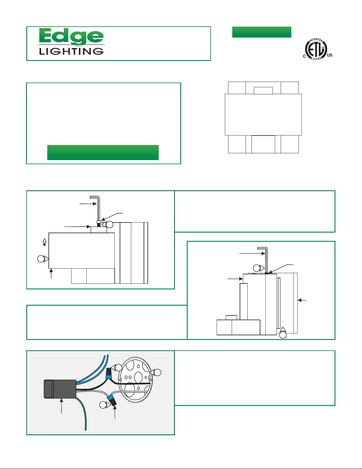
Installation Instructions for Square Crystal
IMPORTANT INFORMATION
- This product is ETL listed for indoor dry locations.
- This product is wall mounted only and it should be
installed as an up light (lamp facing up).
- This product can mount to either a 4" square electrical box
with round plaster ring or an octagon electrical box.
- This product can be dimmed with a low voltage electronic
dimmer.
SAVE THESE INSTRUCTIONS!
Install the Fixture
SQCRY-W-H1-_
904-SQCRY-W-H1-03
A
2
GLASS DIFFUSER
3:
Loosen the two M6 set screws on the top of the fixture
canopy (Do Not Remove) with the provided 3mm Allen
wrench.
4: Pull the mounting plate out of the fixture canopy.
4MM ALLEN
WRENCH
BUSHING
M8 SCREW
1
C
6
7
1: While holding the fixture
bushing with the 4mm Allen wrench.
2: Remove the bushing from the threaded post (Do Not
Remove the Threaded post) and pull the glass diffuser
out.
B
FIXTURE CANOPY
5: Connect the white transformer wire to the neutral power
wire with a wire nut.
6: Connect the black transformer wire to the hot power wire
with a wire nut.
3MM ALLEN
WRENCH
remove the M8 screw on the
M6 SET
3
SCREW
MOUNTING
PLATE
4
TRANSFORMER
5
WIRE NUT
7: Place the transformer and wire nut connections inside the
electrical box.
1
Page 2
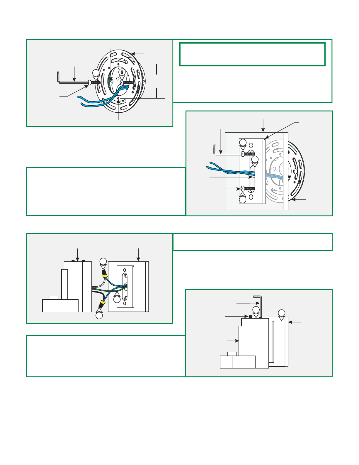
D
3/32 ALLEN WRENCH
#8-32 SCREW
ELECTRICAL BOX HOLE
8
8
CROSSBAR
2-1/16"
NOTE: The two center holes (spaced 2-1/16" apart) on crossbar
should be oriented vertically when mounting to the electrical box
holes.
Mount the crossbar to the electrical box holes with the
8:
provided #8-32 screws using the 3/32 Allen wrench.
9: Make sure that the crossbar and transformer wire are
grounded in accordance with local electrical codes.
CENTER HOLE
10: Feed the transformer wires through the mounting plate
center hole.
11: Align the mounting plate so that the grooved edge of the
bracket faces up ward. Secure the mounting plate to the
crossbar with the provided #8-32 screws using the 3/32
Allen wrench.
F
FIXTURE CANOPY
MOUNTING PLATE
12
E
3/32 ALLEN WRENCH
CENTER
HOLE
#8-32 SCREW
12: Connect each transformer low voltage wire (blue wire) to
one fixture wire with a wire nut.
MOUNTING PLATE
11
10
11
GROOVED
EDGE
CROSSBAR
11
12
13: Place all wires and wire nut connections inside the fixture
canopy.
14: Place the fixture canopy onto the mounting plate and
secure it by tightening the two M6 set screws with the 3mm
Allen wrench.
G
M6 SET SCREW
FIXTURE CANOPY
3MM ALLEN
WRENCH
14
13
MOUNTING
PLATE
2
Page 3

H
WARNING: RISK OF FIRE
Never replace a Xenon (Xelogen) lamp with a regular Halogen
lamp. A regular Halogen lamp requires a protective glass shield.
LAMP
15
SOCKET
16: Slide the glass diffuser back hole onto the threaded post.
Align the glass diffuser center hole with the socket housing
and carefully rest the diffuser onto the fixture canopy.
CAUTION:
lamping, disconnect the power to the fixture.
NOTE: Use only fingers and a soft cloth to install the lamps.
Use MAX 35 Watt Bi-Pin Xenon (Xelogen) Lamp.
15: Push the lamp pins completely into the socket holes.
To reduce risk of a burn or electrical shock during
I
THREADED
POST
16
SOCKET HOUSING
FIXTURE CANOPY
J
M8 SCREW
BUSHING
GLASS DIFFUSER
17
4MM ALLEN
WRENCH
17: Replace the bushing and M8 screw onto the threaded post.
Tighten the M8 screw with the 4mm Allen wrench to secure
the glass diffuser in place.
3
 Loading...