

Page 1
1718 W. Fullerton Ave
Chicago, IL 60614
Tel: 773-770-1195
Fax: 773-935-5613
www.edgelighting.com
© 2010 Edge Lighting. All Rights Reserved.
Installation Instructions for Micro Switch
IMPORTANT INFORMATION
- This instruction shows a typical installation.
- Micro switch is normally closed momentary switch that is
rated for 12A, 125V AC.
SAVE THESE INSTRUCTIONS!
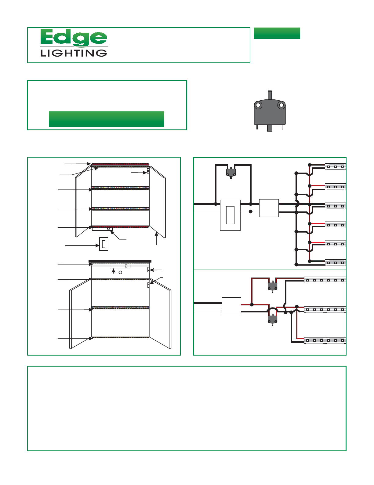
A Typical Cabinet Installation Diagram
SS-MSW
904-SS-MSW-01
A
SS# 9
SS# 8
SS# 7
SS# 6
SS# 5
Electronic Low
Voltage Dimmer
SS# 4
SS# 3
SS#2
SS# 1
PS# 1
SW# 3
PS# 2
GLASS
DOOR
SW# 2
SW# 1
SS#9
120VAC
INPUT
L
N-
120VAC
INPUT
SW#3
Electronic Low
Voltage Dimmer
L
PS#1
N
12VDC
OUTPUT
L
N
12VDC
OUTPUT
+
-
+
PS#2
SW#2
SW#1
SS#8
SS#7
SS#6
SS#5
SS#1
SS#4
SS#3
SS#2
SS#1: Tow kick soft strip.
SS#2 & SS#3: Bottom cabinet soft strips.
SS#4: Drawer soft strip.
SS#5: Under Cabinet soft strip.
SS#6, 7, & 8: Upper Cabinet glass door soft strips.
SS#9: Top of the Cabinet soft strip.
PS#1: PS-60-12VDC, PSB-60-12VDC, or TEB-60-12DC installed behind one of the drawer.
SW#1 & SW#2: Micro switches used in low voltage side to turn the SS#2, SS#3 & SS#4 on when the drawer or cabinet
doors are opened.
PS#2: TEB-60-12DC used with electronic low voltage dimmer to dim the SS#1, SS#5, SS#6, SS#7, SS#8, and SS#9.
SW#3: Micro switch is used in line voltage side to bypass the dimmer and turn to top cabinet soft strips to full power when
the cabinet doors are opened.
Page 2
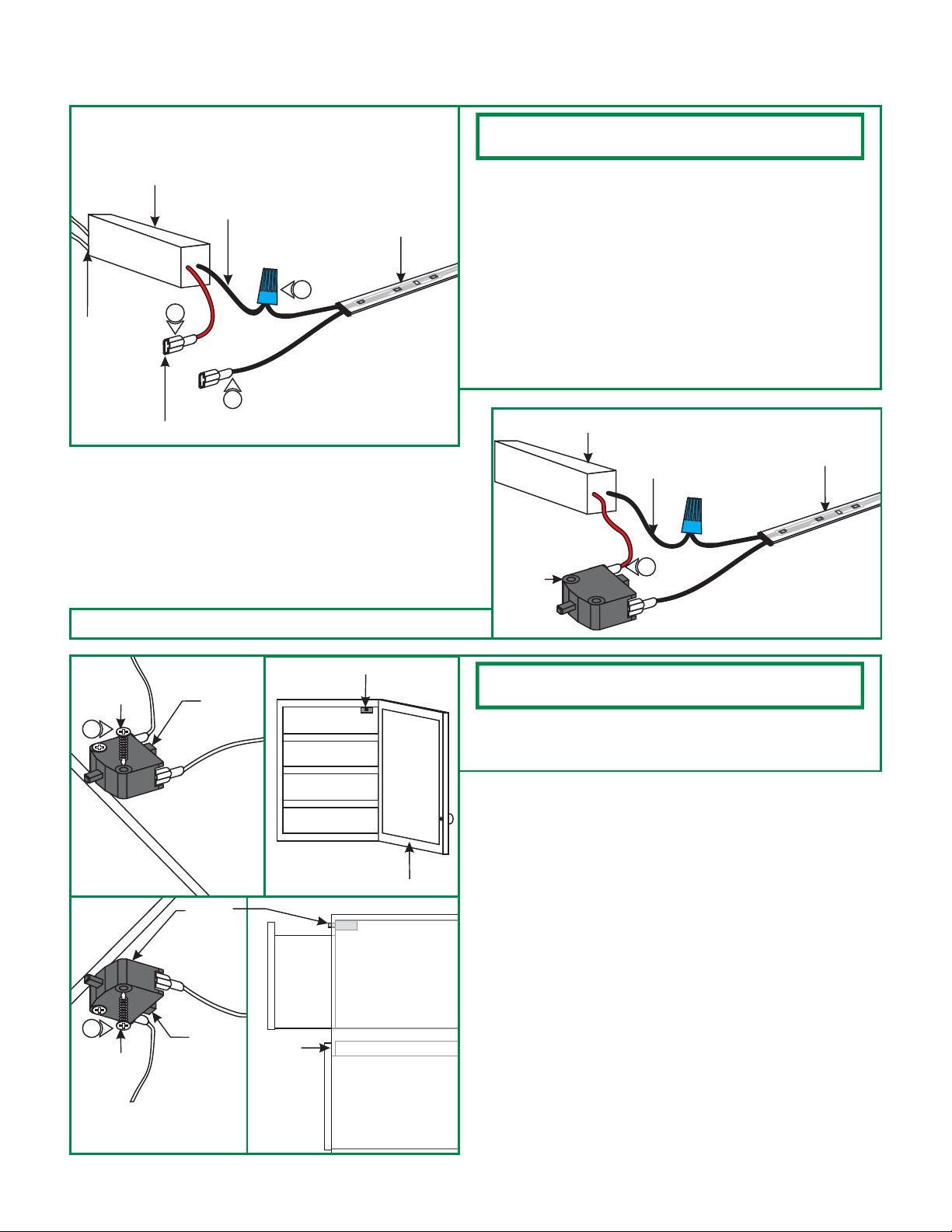
Install the Micro Switch
A
POWER SUPPLY
120V
TERMINAL CONNECTOR
NOTE: The soft strip LED and power supply should be installed
prior to these steps.
1: Insert the soft strip wire connected to the "+ DC" side of the
strip into the terminal connector and use the crimper on the
12V DC
SOFT STRIP LED
-
2
+
3
1
-
+
cylindrical portion of the terminal connector to secure the
wire.
2: Connect the other soft strip wire connected to the "- DC"
side of the strip to the black power supply wire marked " DC" with a wire nut.
3: Connect the red wire marked "+ DC" into the
other terminal connector and use the crimper on the
cylindrical portion of the terminal connector to secure the
wire.
B
SWITCH
power supply
POWER SUPPLY
SOFT STRIP LED
12V DC
4
4: Insert each terminal connector onto one switch prong.
C
SCREW
5
CABINET
INSTALLATION
5
SCREW
SWITCH
SWITCH
DRAWER
SWITCH
CABINET
NOTE: For best results install the switch as close as possible to
the cabinet door hinge or drawer, (shown in drawing C).
5: Properly align the switch position with the cabinet door or
drawer and secure it in place with the provided phillips
screws.
DRAWER
INSTALLATION
2
 Loading...