

Edge Lighting Satin Ceiling User Manual
904-SATIN-F1-02
© 2011 Edge Lighting. All Rights Reserved.
1718 W. Fullerton Ave
Chicago, IL 60614
Tel: 773-770-1195
Fax: 773-935-5613
www.edgelighting.com
info@edgelighting.com
SATIN-_F1_-SN-_
Installation Instructions for Compact Florescent Satin Ceiling 12, 15, & 18
- This product is ETL listed for indoor dry locations.
- This product is ceiling mounted only.
- This product can mount to either a 4" square electrical box
with round plaster ring or an octagon electrical box.
- This instruction shows a typical installation.
- This product is not dimmable.
SAVE THESE INSTRUCTIONS!
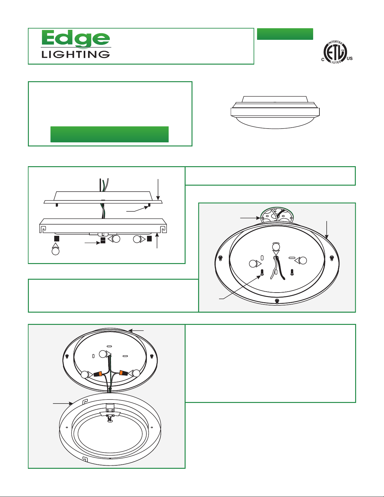
Disassemble the Fixture
1:
A
BACKPLATE
Remove the three thumb nuts from the threaded studs and
detach the backplate from the fixture housing.
Wiring for Standard Installation
THREADED
STUD
B
ELECTRICAL
BOX
BACKPLATE
THUMB
NUT
1
Feed the power wires through the backplate center hole.
1:
Mount the backplate to the electrical box with the provided
2:
two #8-32 screws.
1
C
3
5
FIXTURE
HOUSING
1
FIXTURE HOUSING
BACKPLATE
4
1
2
#8-32
SCREW
3: Make sure that the fixture is grounded in accordance with
local electrical codes.
4: Connect the white fixture wire to the neutral power wire with
a wire nut.
5: Connect the black fixture wire to the hot power wire with a
wire nut.
6: Follow the "Finish Installation" steps on page 3 to complete
the installation.
2
1
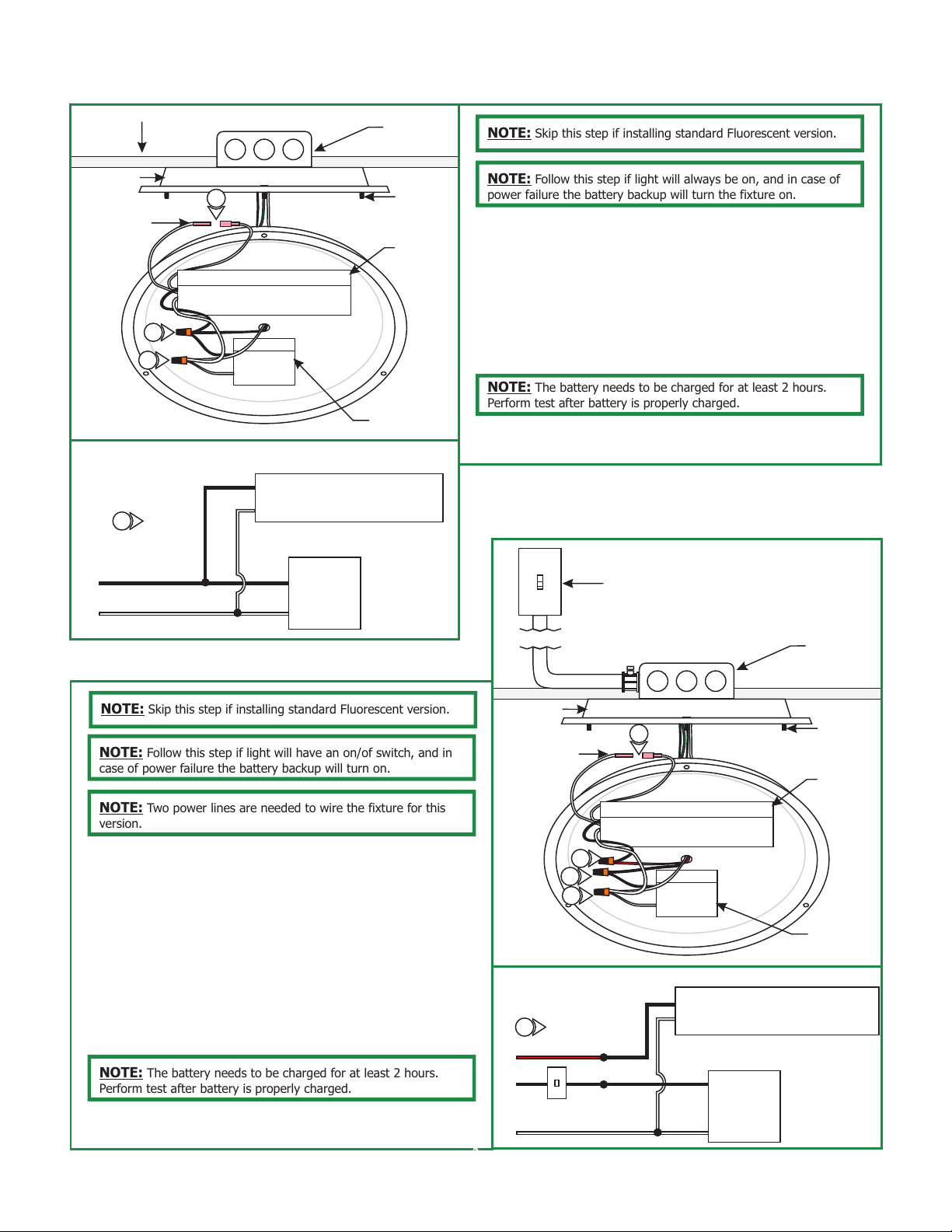
Always on Emergency Light Wiring (F1E Version Only)
D
QUICK
DIS-CONNECT
CONNECTOR
CEILING
BACKPLATE
2
3
PRE-CONNECTED
WIRES NOT SHOWN TO
AVOID CONFUSION
1
(BLK)
L
N
(WH)
ELECTRICAL
BOX
4
THREADED
STUD
NOTE: Skip this step if installing standard Fluorescent version.
NOTE: Follow this step if light will always be on, and in case of
power failure the battery backup will turn the fixture on.
1: Follow wiring diagram in Drawing D to properly install fixture.
BATTERY
2: Connect the hot power wire to the battery & ballast black
wires with a wire nut.
3: Connect the neutral power wire to the battery & ballast white
wires with a wire nut.
4: Connect the quick dis-connect connector together.
NOTE: The battery needs to be charged for at least 2 hours.
Perform test after battery is properly charged.
BALLAST
5: Refer to "Finish Installation" steps on page 3 to complete the
installation.
BATTERY
Switch Controlled Emergency
Light Wiring (F1E Version Only)
E
BALLAST
SWITCH
NOTE: Skip this step if installing standard Fluorescent version.
NOTE: Follow this step if light will have an on/of switch, and in
case of power failure the battery backup will turn on.
NOTE: Two power lines are needed to wire the fixture for this
version.
1: Follow wiring diagram in Drawing E to properly install fixture.
2: Connect the white ballast & battery wires to neutral power
wire with a wire nut.
3: Connect the hot power wire coming from the switch to the
black wires of the ballast with a nut.
4: Connect the other hot power wire to the black wire of the
battery with a wire nut.
5: Connect the quick dis-connect connector together.
NOTE: The battery needs to be charged for at least 2 hours.
Perform test after battery is properly charged.
6: Refer to "Finish Installation" steps on page 3 to complete the
installation.
BACKPLATE
QUICK
DIS-CONNECT
CONNECTOR
4
3
2
PRE-CONNECTED
WIRES NOT SHOWN
TO AVOID CONFUSION
1
(RED)
L1
L2
SWITCH
N
(BLK)
(WH)
5
(BLK)
ELECTRICAL
BOX
THREADED
STUD
BATTERY
BALLAST
BATTERY
BALLEST
2
 Loading...