

Page 1
© 2011 Edge Lighting. All Rights Reserved.
1718 W. Fullerton Ave
Chicago, IL 60614
Tel: 773-770-1195
Fax: 773-935-5613
www.edgelighting.com
info@edgelighting.com
SATIN-_H1-SN-_
Installation Instructions for Satin Ceiling 7, 12, 15, & 18
IMPORTANT SAFETY INSTRUCTIONS
To reduce the risk of fire, electrical shock, exposure to
excessive UV radiation, or injury to persons:
- Use this fixture indoors only.
- Do not look directly at the lamp while the fixture is on.
- RISK OF FIRE: Use only the type of lamp and maximum
wattage indicated in this instruction manual.
- Never cover the halogen lamp with anything other than a
lamp shade provided by Edge Lighting and never place
flammable material close to the fixture.
- Never turn the fixture on and off by connecting and
disconnecting the halogen lamp.
- Do not touch the fixture head, shade or lamp shield while
the fixture is on. These surfaces may be VERY HOT.
- Do not touch lamp at anytime. Use a soft cloth instead as oil
from skin may damage lamp.
- It is normal for a new halogen lamp to produce minor
smoke when first turned on.
- Turn power off and allow to cool before replacing lamp.
IMPORTANT INFORMATION
- This product is ETL listed for indoor dry locations.
- This product is ceiling mounted only.
- This product can mount to either a 4" square electrical box
with round plaster ring or an octagon electrical box.
- This product can be dimmed with a standard incandescent
dimmer.
SAVE THESE INSTRUCTIONS!
904-SATIN-H1-02
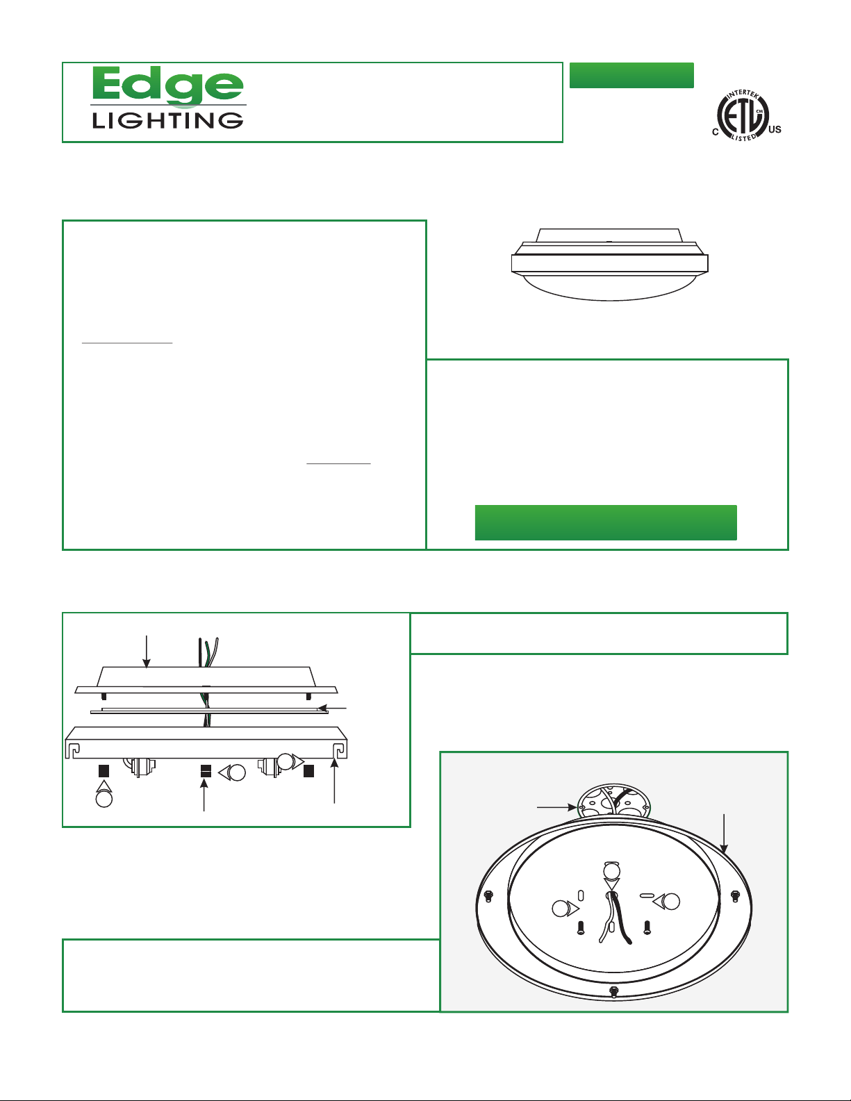
Install the Fixture
A
2:
3:
#8-32 screws.
BACKPLATE
INSULATION
PAD
1
1
THUMB NUT
Feed the power wires through the backplate center hole.
Mount the backplate to the electrical box with the provided
1
FIXTURE HOUSING
1:
Remove the three thumb nuts from the threaded studs and
detach the backplate from the fixture housing.
B
ELECTRICAL BOX
3
2
BACKPLATE
2
1
Page 2
C
BACKPLATE
4: Insert the power wires through the insulation pad.
5: Make sure that the fixture is grounded in accordance with
local electrical codes.
6: Connect the white fixture wire to the neutral power wire with
a wire nut.
4
INSULATION
PAD
FIXTURE
HOUSING
7
5
6
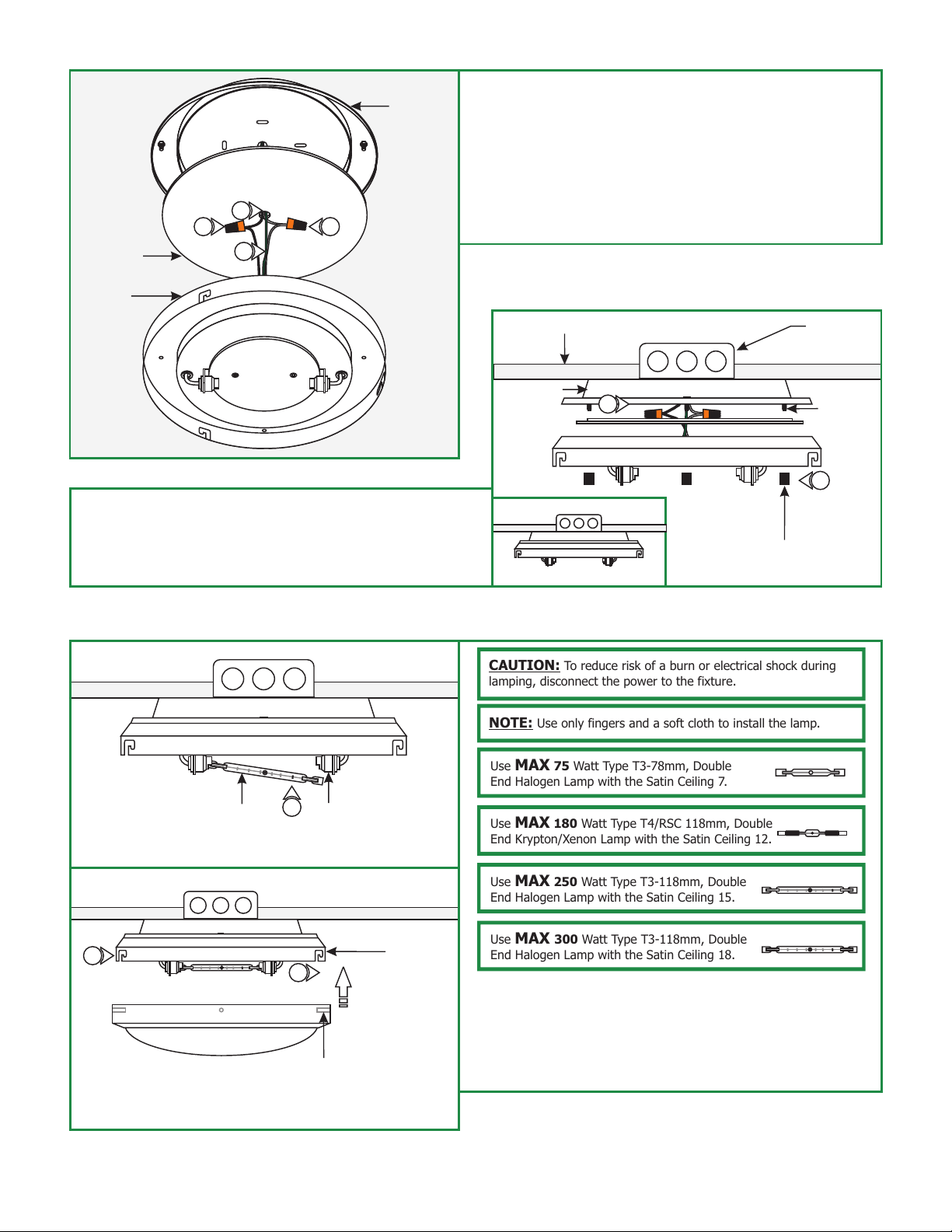
8: Place all wire and wires nuts connections inside backplate.
9: Align and push the fixture housing onto threaded studs and
tighten the three thumb nuts completely to secure the fixture
housing in place.
Install the Lamp & Glass Shade
E
7: Connect the black fixture wire to the hot power wire with a
wire nut.
CEILING
D
BACKPLATE
8
THUMB NUT
ELECTRICAL
BOX
THREADED
STUD
9
CAUTION: To reduce risk of a burn or electrical shock during
lamping, disconnect the power to the fixture.
NOTE: Use only fingers and a soft cloth to install the lamp.
Use MAX 75 Watt Type T3-78mm, Double
End Halogen Lamp with the Satin Ceiling 7.
1
LAMP
2
SOCKET
2
FIXTURE
HOUSING
SLOT
Use MAX 180 Watt Type T4/RSC 118mm, Double
End Krypton/Xenon Lamp with the Satin Ceiling 12.
Use MAX 250 Watt Type T3-118mm, Double
End Halogen Lamp with the Satin Ceiling 15.
Use MAX 300 Watt Type T3-118mm, Double
End Halogen Lamp with the Satin Ceiling 18.
1: Place one end of the lamp onto one socket pin, while
pushing the lamp against that socket pin slide the other end
onto the other socket pin.
SHADE POST
2: Insert the three shade posts into the fixture housing slots
and turn clockwise to lock into place.
2
 Loading...