

Edge Lighting Rocky Ceiling User Manual
© 2010 Edge Lighting. All Rights Reserved.
1718 W. Fullerton Ave
Chicago, IL 60614
Tel: 773-770-1195
Fax: 773-935-5613
www.edgelighting.com
info@edgelighting.com
ROC-C-H1-_
Installation Instructions for Rocky Ceiling MR16 Version
IMPORTANT SAFETY INSTRUCTIONS
To reduce the risk of fire, electrical shock, exposure to
excessive UV radiation, or injury to persons:
- Do not look directly at the lamp while the fixture is on.
- RISK OF FIRE: Use only the type of lamp and maximum
wattage indicated in this instruction manual.
- Never cover the halogen lamp with anything other than a
lamp shield provided by Edge Lighting and never place
flammable material close to the fixture.
- Never turn the fixture on and off by connecting and
disconnecting the halogen lamp.
- Do not touch the fixture head, shade or lamp shield while
the fixture is on. These surfaces may be VERY HOT.
- Do not touch lamp at anytime. Use a soft cloth instead as oil
from skin may damage lamp.
- It is normal for a new halogen lamp to produce minor
smoke when first turned on.
- Turn power off and allow to cool before replacing lamp.
IMPORTANT INFORMATION
- This product is ETL listed for indoor and outdoor locations.
- This product is for ceiling mount applications only.
- This product can mount to either a 4" square electrical box
with round plaster ring or an octagon electrical box.
- This product can be dimmed with a standard electronic
low voltage dimmer.
- This instruction shows a typical installation for indoor or
outdoor applications.
SAVE THESE INSTRUCTIONS!
904-ROC-C-H1-04
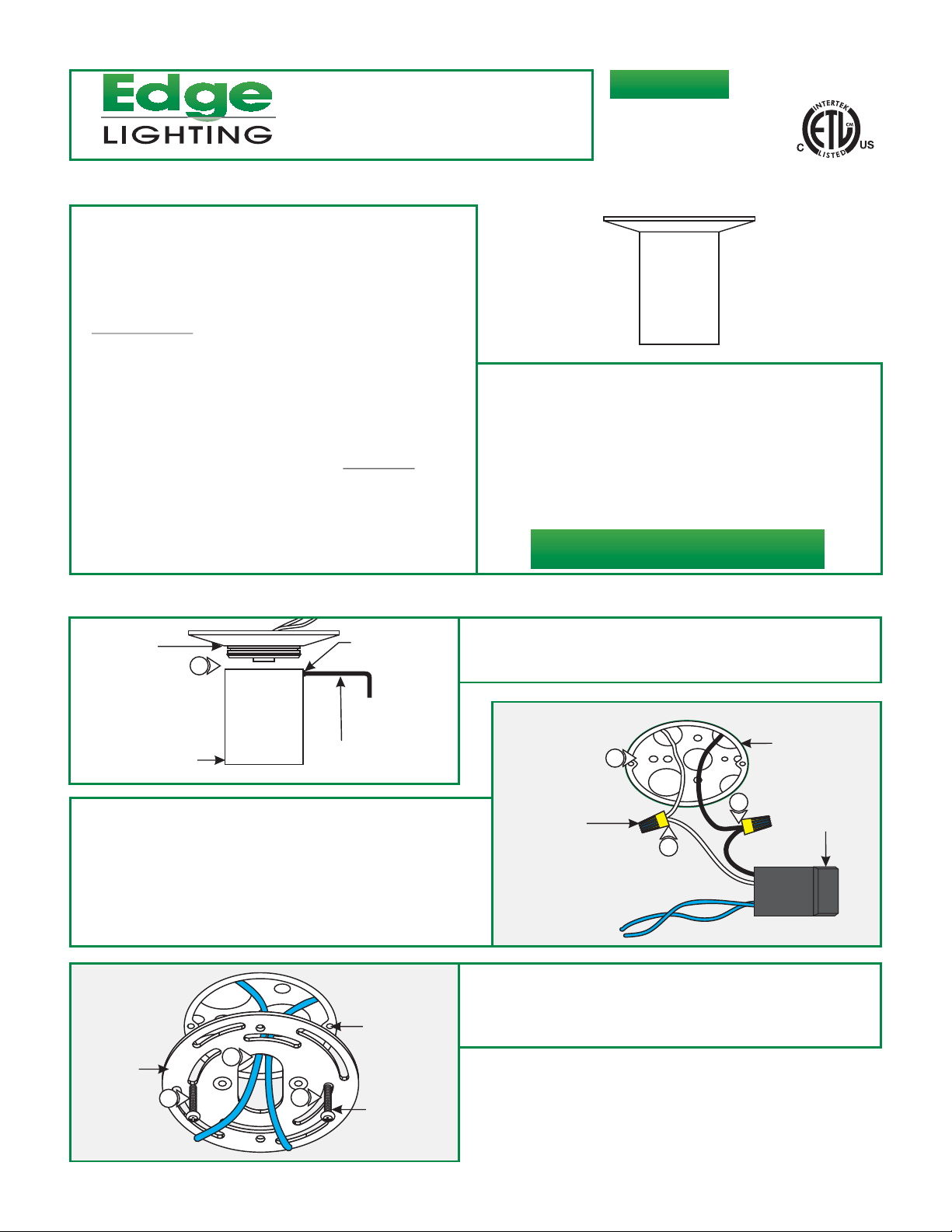
Install the Fixture
A
CANOPY
1
METAL SHADE
2: Connect the white transformer wire to the neutral power
wire with a wire nut.
3: Connect the black transformer wire to the hot power wire
with a wire nut.
4: Place the transformer and wire nut connections inside the
electrical box.
M4 SET SCREW
2MM ALLEN
WRENCH
C
ELECTRICAL
BOX THREADED
CROSSBAR
5
HOLE
1: Loosen the M4 set screw (DO NOT REMOVE) on the metal
shade with the 2MM Allen wrench provided, and pull the
metal shade completely off of the canopy.
B
4
WIRE NUT
2
5:
Feed the transformer wires through the crossbar center hole.
6:
Mount the crossbar to the electrical box threaded holes with
the provided #8-32 screws.
ELECTRICAL BOX
3
TRANSFORMER
6
6
#8-32 SCREW
1
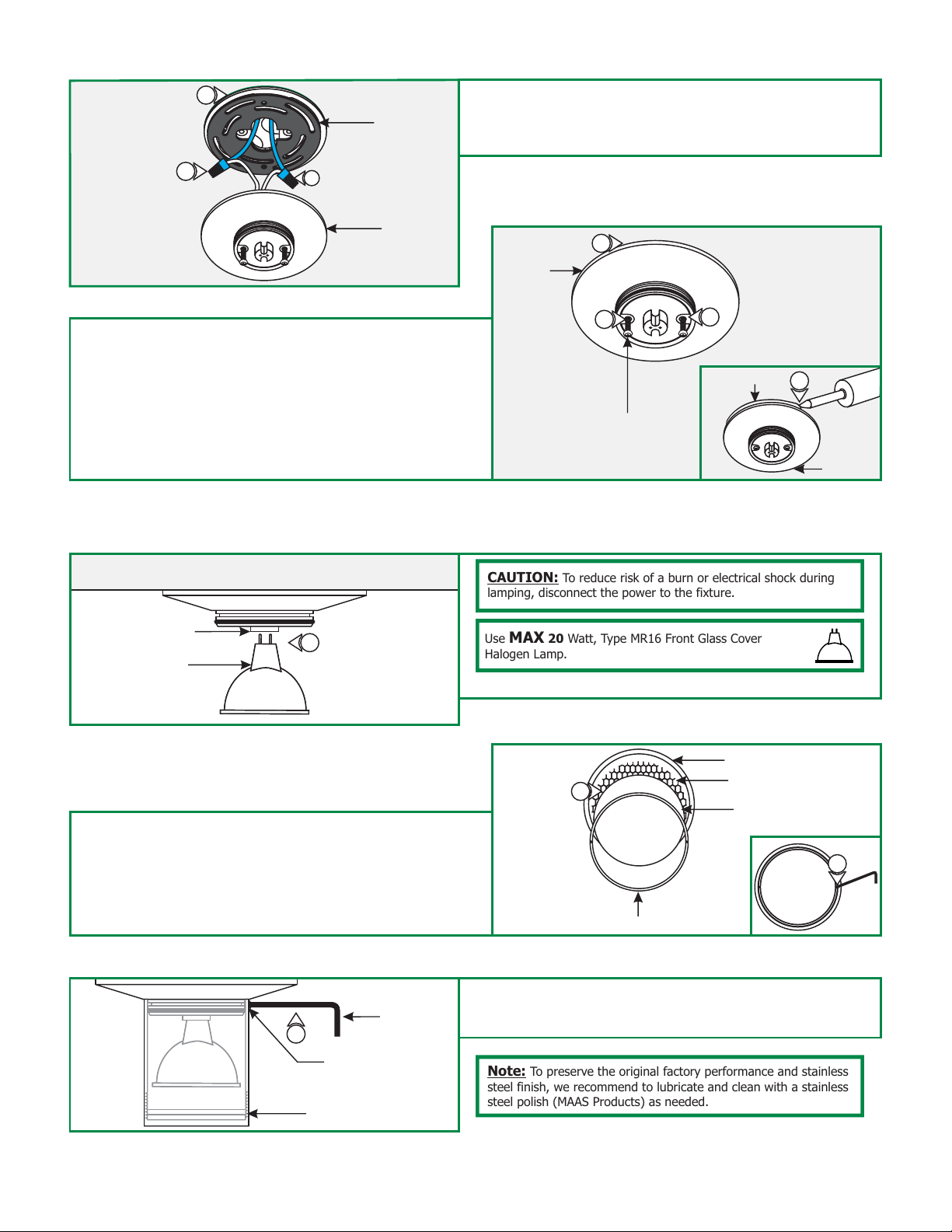
D
7
GASKET
8
8
7: Slide the gasket against the crossbar.
8: Connect each transformer low voltage wire (blue wire) to one
fixture wire with a wire nut.
CANOPY
9: Place all wires and wire connections inside the electrical
box.
10: Align the fixture canopy holes with the gasket and crossbar
holes, and secure the canopy to the electrical box by
tightening the two #10-32 Phillips screws.
11: For installation in wet location, caulk around the fixture
canopy with waterproof construction sealant.
Install the Lamp
F
SOCKET
LAMP
1
E
CANOPY
#10-32 PHILLIPS SCREW
CAUTION:
lamping, disconnect the power to the fixture.
Use MAX 20 Watt, Type MR16 Front Glass Cover
Halogen Lamp.
1: Push the lamp pins completely into the socket holes.
9
10
To reduce risk of a burn or electrical shock during
10
SEALANT
11
CANOPY
2: Optional: To add a additional lens(es) (sold separately), use
a small Allen wrench to loosen and remove the lens holder
ring from inside the metal shade.
3: Place the lens(es), or a combination of lens(es) and a hexcell
louver into the shade (maximum 3). Replace and tighten the
lens holder ring to secure the lenses in place.
H
4
M4 SET
SCREW
METAL SHADE
2MM ALLEN
WRENCH
G
3
LENS HOLDER RING
4: Push the metal shade completely onto the canopy and secure
it in place by tightening the M4 set screw with the 2mm Allen
wrench.
Note: To preserve the original factory performance and stainless
steel finish, we recommend to lubricate and clean with a stainless
steel polish (MAAS Products) as needed.
SHADE
HEXCELL LOUVER
LENS
2
 Loading...