

Page 1
1718 W. Fullerton Ave
Chicago, IL 60614
Tel: 773-770-1195
Fax: 773-935-5613
www.edgelighting.com
© 2014 Edge Lighting. All Rights Reserved.
info@edgelighting.com
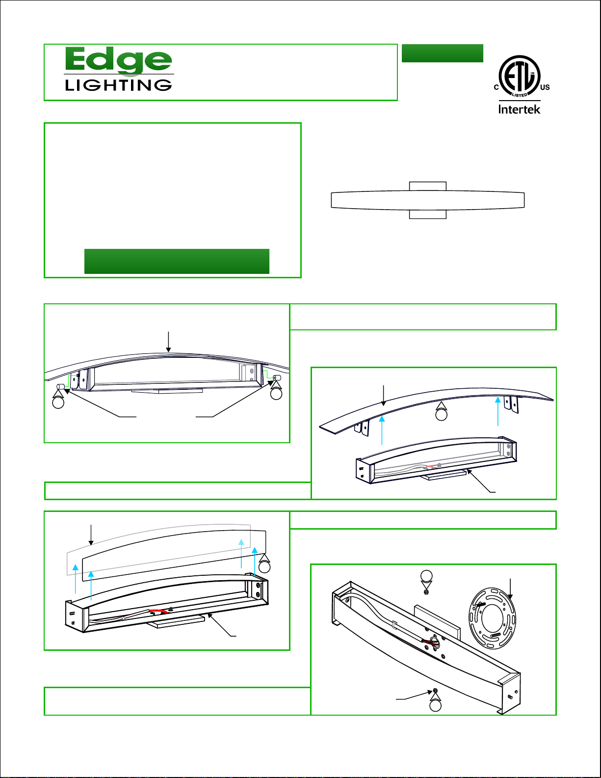
Installation Instructions for Regal LED
IMPORTANT SAFETY INSTRUCTIONS
- Use this fixture indoors only.
- This product is ETL listed for indoor dry locations.
- This product is wall mounted only.
- This product can mount to either a 4" square junction box
with round plaster ring or an octagon junction box.
- This product can be dimmed with a standard low-voltage
electronic dimmer.
- This product must be installed by a qualified electrician.
- Before beginning any electrical work, ensure that
power to the junction box is turned OFF.
SAVE THESE INSTRUCTIONS!
Install the Fixture
A
FRONT COVER
REGAL-L1-_
M2-IND-_
Remove the two thumb nuts on the sides of the fixture
1:
body to detach front cover.
904-REGAL-L1-01
1
THUMB NUTS
2: Remove the front cover from the fixture.
GLASS PANEL
3
FIXTURE
B
1
3: Slide the glass panels out of the slots in the fixture.
FRONT COVER
2
4
FIXTURE
CROSSBAR
4: Loosen and remove the two hex nuts and lock washers from
the center of fixture body to remove the crossbar assembly.
HEX NUT/
LOCK WASHERS
4
1
Page 2
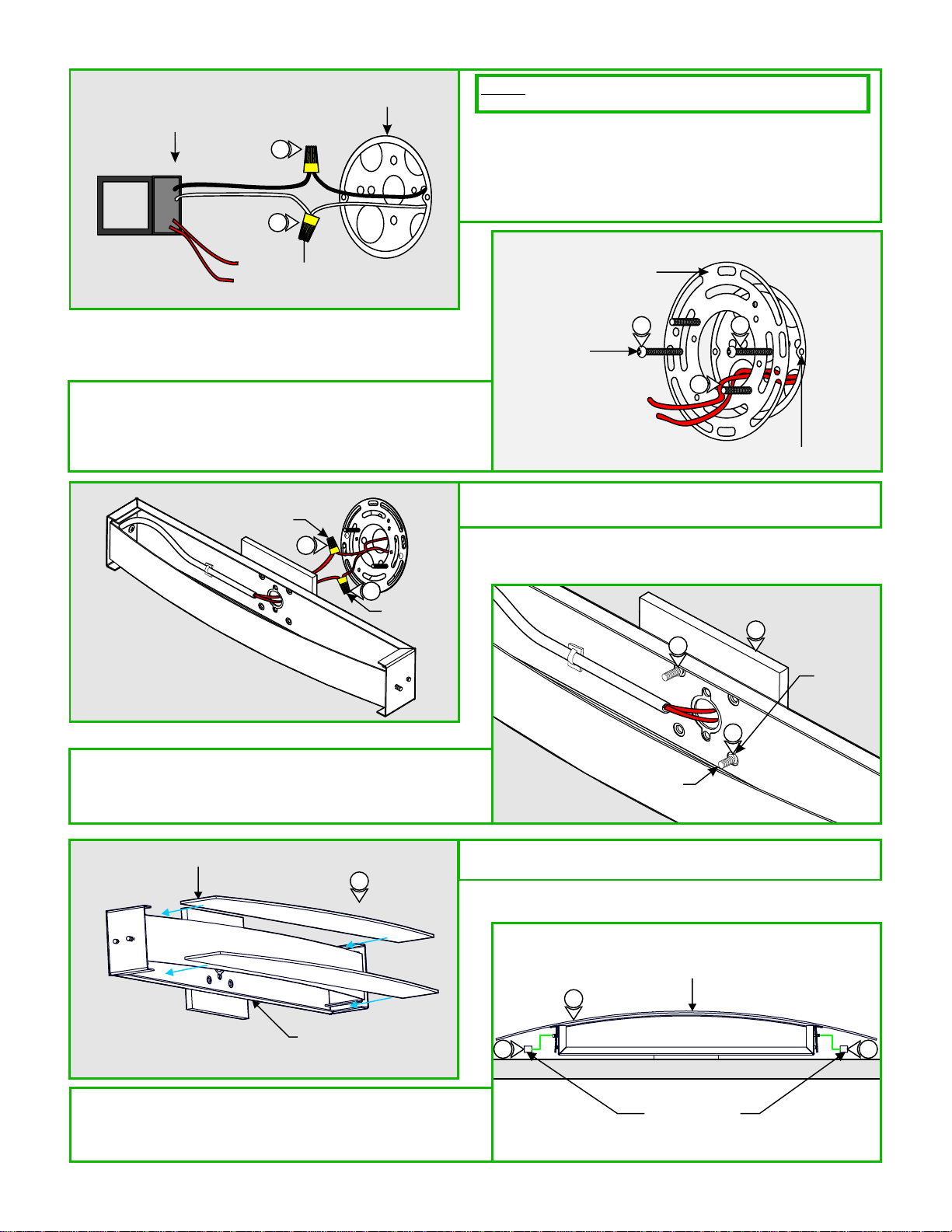
LED DRIVER
5
6
WIRE NUT
JUNCTION BOX
WALL
NOTE: Make sure the power to the electrical box is off before
continuing.
Connect the black LED driver wire to the HOT wire in the
5:
junction box.
Connect the white LED driver wire to the NEUTRAL wire
6:
in the junction box. Place wire connections and LED driver
into the junction box.
CROSSBAR ASSEMBLY
WALL
Feed the power wires through the crossbar assembly center
7:
hole.
8: Mount the crossbar o the junction box holes with
assembly t
the provided two #8-32 screws.
WALL
WIRE NUT
9
9
WIRE NUT
Slide the canopy holes onto the threaded crossbar studs
10:
11: Secure the fixture to the crossbar studs using the two hex
nuts and lock washers.
8
#8-32 SCREW
9:
Connect each fixture wire to one red LED driver wire
8
7
JUNCTION BOX HOLE
using wire nuts.
10
11
11
STUD
WALL
HEX NUT/
LOCK
WASHERS
GLASS PANEL
12
FIXTURE
13: Replace the front cover.
14: Replace the thumb nuts onto the mounting screws and
tighten to secure front cover in place.
12:
Slide the glass panels into top and bottom of slots of the
fixture.
FRONT COVER
13
14
THUMB NUTS
14
2
 Loading...