

Edge Lighting PSB-96W-010-24VDC User Manual
PSB-96W-010-24VDC-05
1718 W. Fullerton Ave
Chicago, IL 60614
Tel: 773-770-1195
Fax: 773-935-5613
www.edgelighting.com
info@edgelighting.com
© 2014 Edge Lighting. All Rights Reserved.
Installation Instructions for 96 Watt 24 Volt DC Power Supply with
0-10 Volt Dimming Module
SAVE THESE INSTRUCTIONS!
GENERAL INFORMATION IMPORTANT SAFETY INSTRUCTIONS
- RISK OF FIRE: This product must be installed by a
qualified electrician. Turn the power to the electrical box off
during installation. Read the "Important Safety Instructions "
before installation.
- This product is not suitable for wet locations. It is approved
for the use at any height above the finished floor.
- A typical installation is shown. Specific installation must be
in accordance with the local electrical codes.
- TO REDUCE RISK OF FIRE, it is important to wire the
power supply for the system as described in this
installation instruction.
- Load the power supply to MAXIMUM 96 Watts.
- Use Lightolier "ZP600FAM120" 0-10 volt controller to dim
the LED soft strip (fixture).
- For multiple parallel runs, do not exceed 32' total length.
- Do not install this power supply in a wet location.
- To reduce the risk of the system overheating and possibly
causing a fire, make sure all the connections are tight.
- Do not install *LED fixture closer than three inches or as
specified in the *LED fixture installation instructions to
curtains or similarly combustible materials. Keep insulation
at least 3" away from the enclosure.
- Turn the electrical power off before modifying the lighting
system in any way.
- The system is "ETL" listed for USA and Canada only when
all the products used are supplied by Edge Lighting.
* See LED fixture installation instructions for proper
placement.
1
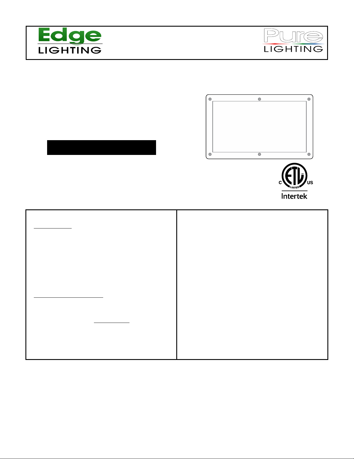
Install the Power Supply
A
PHILLIPS SCREW
input 120VAC
WH (N)
BK (L)
input 0-10V
PUR
GRY
POWER SUPPLY
RED (24VDC+)
BLUE (RETURN-)
YELLOW (DIM RETURN-)
1
COVER
CASE
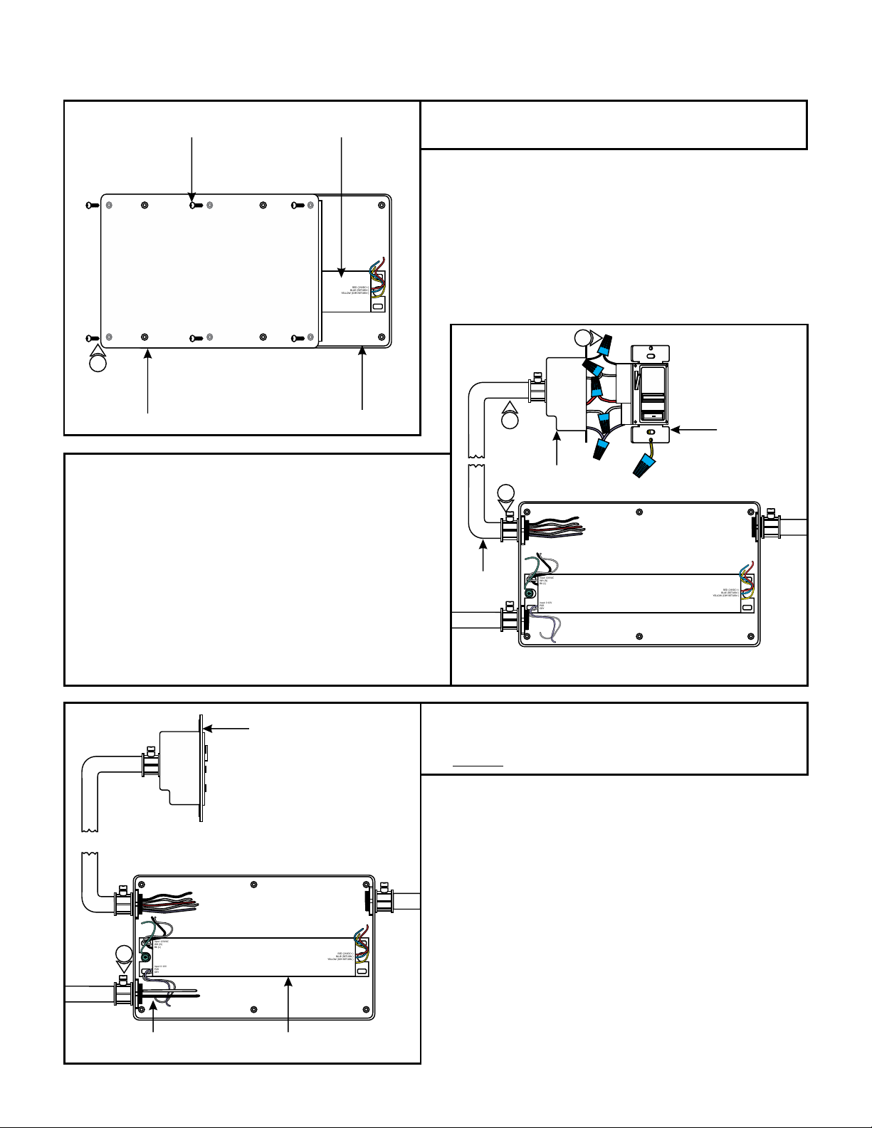
2: Install conduits from the controller electrical box to main
panel and soft strip to the power supply case.
3: Run proper wire size and color from the controller (switch)
electrical box to the power supply case.
1: Loosen and remove the six Phillips screws on the front of
the power supply cover to remove the cover from the case.
B
2
ELECTRICAL BOX
3
4
LIGHTOLIER:
ZP600FAM120
CONTROLLER
4: Connect the black, white, red, purple, and gray controller
wires respectively to black, white, red, purple, and gray wires
with a wire nut. The yellow controller wire is not used in this
procedure. Cap the yellow controller wire with a wire nut. For
three way switching, refer to the instructions provided with
the controller.
5: Secure controller to the electrical box.
C
input 120VAC
WH (N)
BK (L)
6
input 0-10V
PUR
GRY
LIGHTOLIER:
ZP600FAM120
CONTROLLER
RED (24VDC+)
BLUE (RETURN-)
YELLOW (DIM RETURN-)
input 120VAC
CONDUIT
WH (N)
BK (L)
input 0-10V
PUR
GRY
RED (24VDC+)
BLUE (RETURN-)
YELLOW (DIM RETURN-)
6: Run the 120 volt power line wires from the panel to the
power supply case.
7: DO NOT connect the power wires to the panel at this time.
120 VOLT POWER
LINE WIRES
POWER SUPPLY
2
 Loading...