

Page 1
1718 W. Fullerton Ave
Chicago, IL 60614
Tel: 773-770-1195
Fax: 773-935-5613
www.edgelighting.com
© 2012 Edge Lighting. All Rights Reserved.
info@edgelighting.com
Installation Instructions for Plaza Large
IMPORTANT INFORMATION
- This product is ETL listed for indoor dry locations.
- This product is wall mounted only.
- Supply power to mirror in accordance with local electrical
codes.
- This instruction shows a typical installation
- This product is dimmable with 0-10V dimmers.
SAVE THESE INSTRUCTIONS!
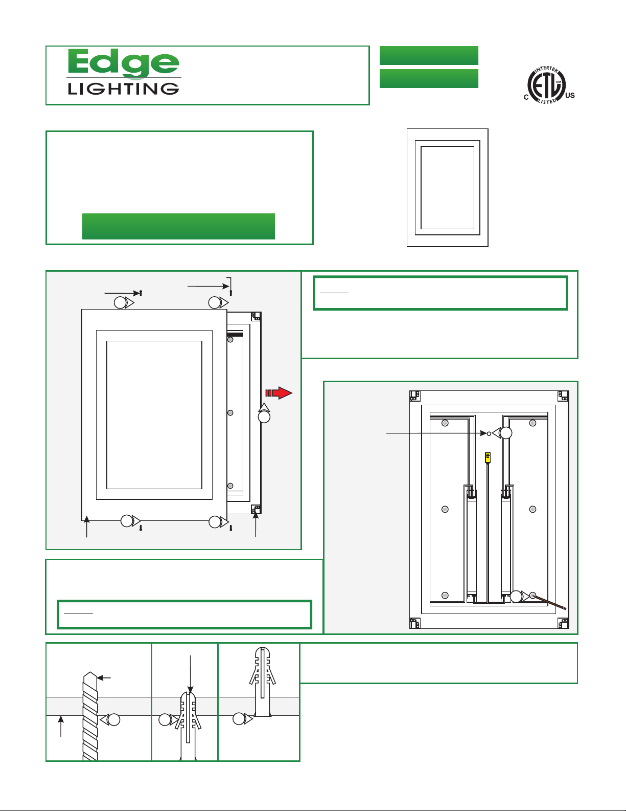
Install the Mounting Plate
PLAZA-L-F1-_
PLAZA-L-F1D-_
904-PLAZA-L-F1D-05
1
3MM ALLEN
WRENCH
1
GNL
GNL
1
2
MOUNTING PLATE
A
M6 SCREW
1
MIRROR
3: Align the mounting plate hole with the power line conduit, or
electrical box, and use the mounting plate as a template to
mark four mounting holes onto the wall.
NOTE: Make sure that the mounting plate is leveled
horizontally.
NOTE: It is recommended that one person holds the mounting
plate while the electrician installs it.
1: Loosen and remove the four M6 screws on the top and
bottom of the mounting plate with the 3mm Allen wrench.
2: Pull the mounting plate completely out of the mirror.
B
MOUNTING PLATE
CENTER HOLE
3
GNL
GNL
3
C
WALL
9/32
DRILL BIT
4
5
ANCHOR
4: Use a 9/32 drill bit to make holes on all six marked points.
5: Tap the anchors into the drilled holes with a hammer.
5
1
Page 2
D
#8-32 SCREW
MOUNTING
PLATE
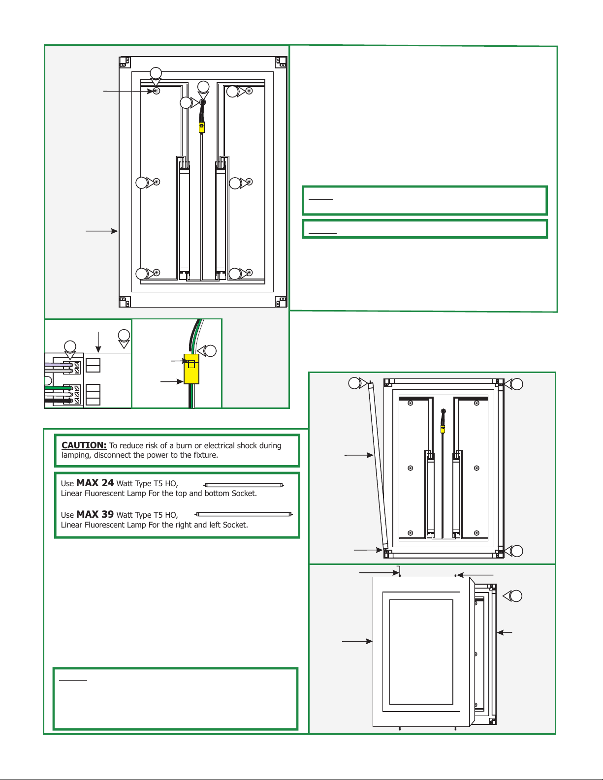
6: Install the conduit connector (not provided) to mounting
plate hole. Feed the power line through the conduit
8
6
8
10
GNL
GNL
connector into the mounting plate.
8: Line up the mounting plate holes with the anchors and
secure it to the anchors with the six #8-32 screws
provided.
9: Make sure that the mounting plate is grounded in
accordance with local electrical codes.
10: Connect the hot, neutral power wires into the wago
8
8
connector.
NOTE: If necessary, push the tab down and then pull the Wago
connector for a quick disconnect.
NOTE: Omit steps 11 & 12 for non-dimming wiring.
11: For dimming, run the violet and gray wires from the
dimmer each ballast. The wires must be solid copper
8
8
(refer to the dimmer instruction for more details).
12: Branch the violet wire to the (+) & the gray wire (-)
terminals of each ballast respectively.
12
BALLAST
VIOLET
GRAY
GREEN
WHITE
BLACK
(+) Dimming
(-) Control
G
N
L
11
WAGO
CONNECTOR
TAB
10
GNL
GNL
CAUTION: To reduce risk of a burn or electrical shock during
lamping, disconnect the power to the fixture.
Use MAX 24 Watt Type T5 HO,
Linear Fluorescent Lamp For the top and bottom Socket.
Use MAX 39 Watt Type T5 HO,
Linear Fluorescent Lamp For the right and left Socket.
13: Line up the lamp pins on both sides with the opening on the
socket.
14: Insert the lamp pins all the way into the sockets and turn
the lamp to lock it in place. Repeat this step for the other
lamp.
15: Place the mirror housing onto the mounting plate and
secure it in place by tightening the four #8 screw on the
top and bottom of the mirror housing into the mounting
plate.
E
LAMP
SOCKET
3MM ALLEN
WRENCH
MIRROR
HOUSING
13
14
GNL
GNL
13
M6 SCREW
14
GNL
GNL
MOUNTING
PLATE
NOTE: NEMA fluorescent lamp manufacturers recommend to
reduce possible flicker or instability when new dimming systems
are comissioned, lamps should be operated at the ballast's
maximum light output setting overnight (approximately
12 hours).
2
 Loading...