

Page 1
© 2009 Edge Lighting. All Rights Reserved.
1718 W. Fullerton Ave
Chicago, IL 60614
Tel: 773-770-1195
Fax: 773-935-5613
www.edgelighting.com
info@edgelighting.com
MP-4RD-OUT-_
Installation Instructions for Monorail Out Rigger Power Feed
IMPORTANT INFORMATION
- This product is ETL listed for indoor dry locations.
- This product can be installed to a 4" electrical box with
round plaster ring, or to an octagon electrical box.
- Minimum electrical box volume must be 6 cubic inches
(98 cubic centimeters).
- This product should be installed by a qualified electrician.
SAVE THESE INSTRUCTIONS!
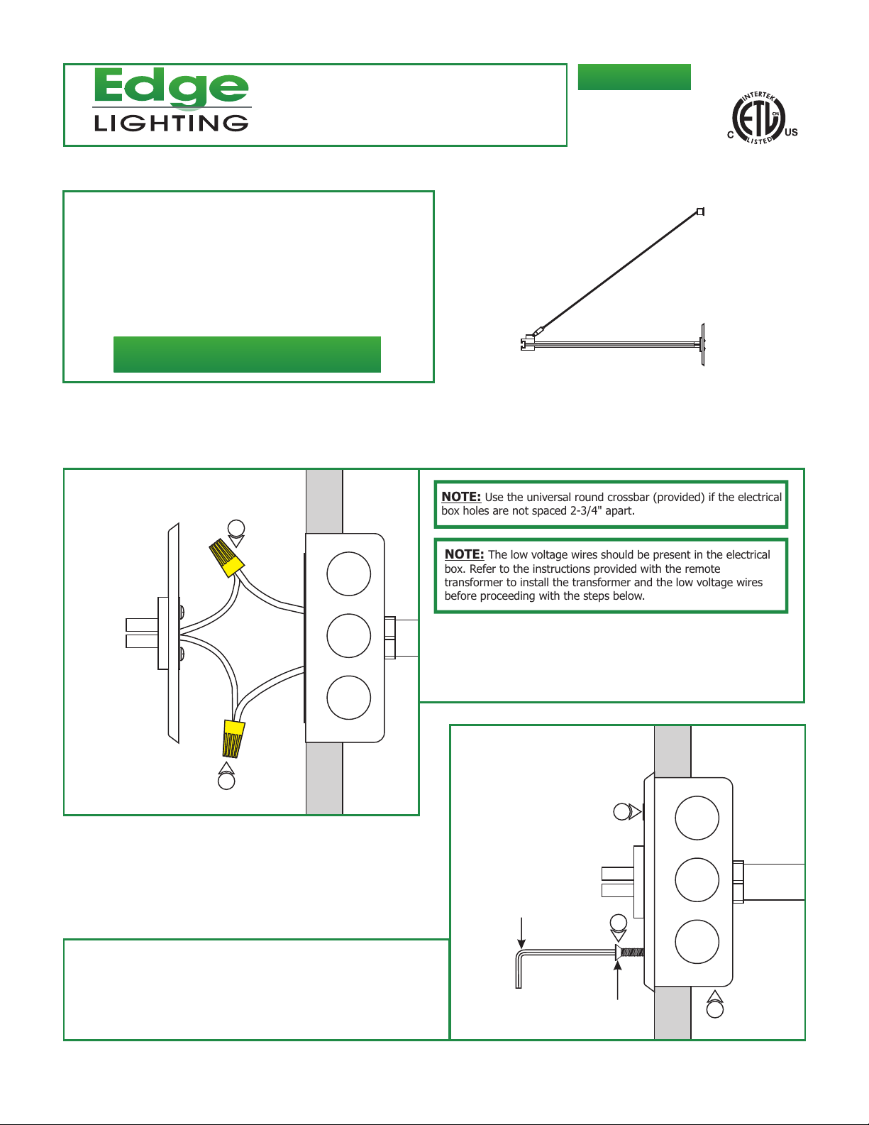
Install the Power Feed Canopy
904-MP-4RD-OUT-02
A
NOTE: Use the universal round crossbar (provided) if the electrical
box holes are not spaced 2-3/4" apart.
2
NOTE: The low voltage wires should be present in the electrical
box. Refer to the instructions provided with the remote
transformer to install the transformer and the low voltage wires
before proceeding with the steps below.
1: Turn the power to electrical box off.
2: Connect each low voltage wire coming from the remote
transformer to one power feed canopy wire with a wire nut.
B
2
4
3: Place all wires and wire nut connections inside the electrical
box.
4: Secure the power feed canopy to the electrical box by
tightening the two provided #8-32 screws with the 3/32
Allen wrench.
3/32 ALLEN WRENCH
4
#8-32
SCREW
3
1
Page 2
C
OUT RIGGER ARM
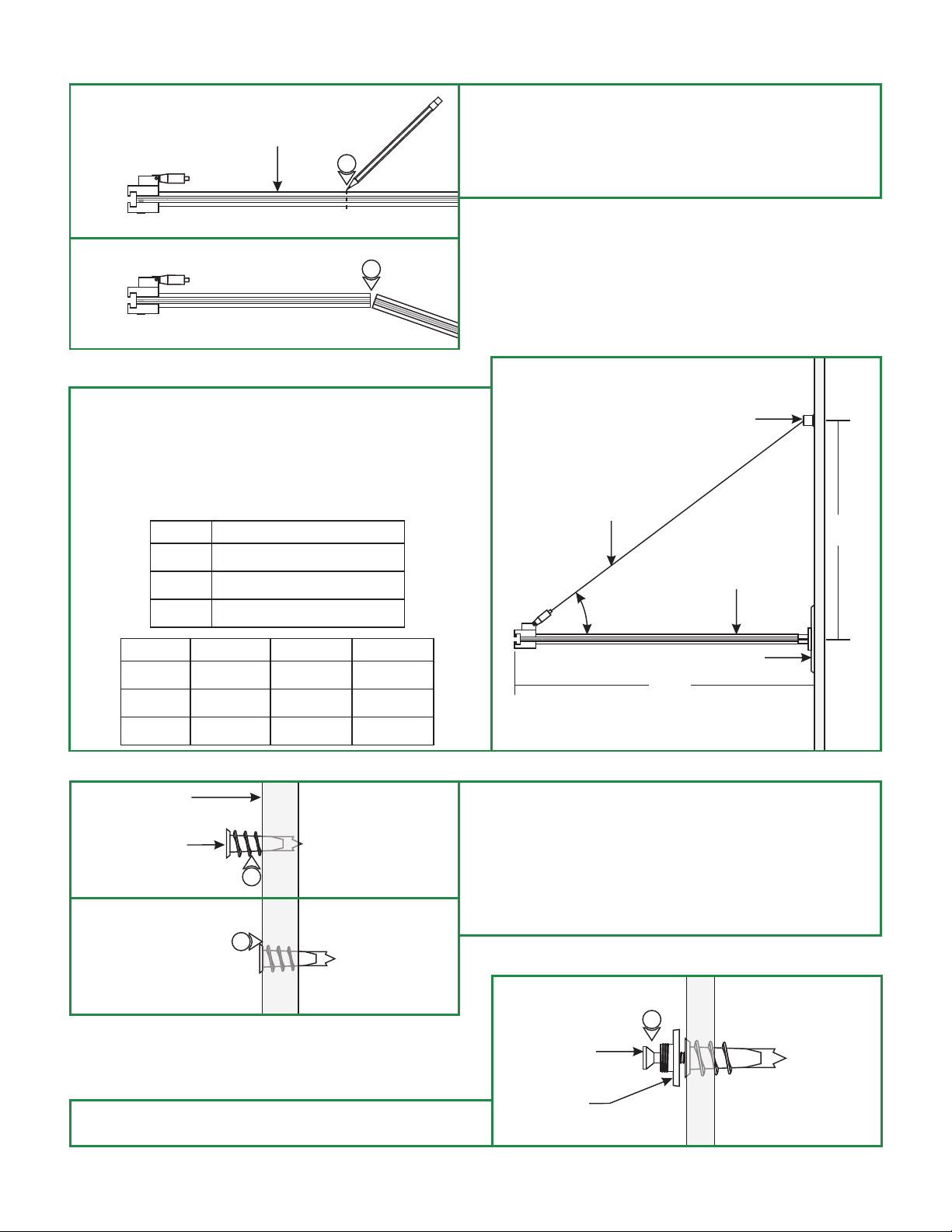
5: From the end of the out rigger arm, mark the point where
out rigger arm
the needs to be shortened. (Optional)
5
6
6: Cut at the marked point with a hacksaw.
7: Clean the inside and the outside burrs where cut.
D
8: The cable post should be installed above the power feed
canopy so that there is a minimum of a 30° angle between
the out rigger arm and the aircraft cable to properly lock the
aircraft cable in position.
9: Use the tables below to determine the cable post position
relative to the out rigger arm for various angles.
ANGLE EQUATION FOR HEIGHT (H)
E
30°
45°
60°
LENGTH(L) (H) FOR 30° (H) FOR 45° (H) FOR 60°
36"
24"
12"
WALL
ANCHOR
H = 0.6 x L
H = L
H = 1.7 X L
21"
14"
7"
11
12
36"
24"
12"
62"
42"
21"
CABLE POST
AIRCRAFT CABLE
H
OUT RIGGER ARM
30°
CANOPY
L
10: Mark the cable post location on the wall above the canopy.
(See table above for measurements).
11:
Using a hammer tap in the anchor on the marked
location up to the threaded portion.
12: Screw in the threaded portion of the anchor with a Phillips
screwdriver.
13: Mount the integrated washer-nipple to the anchor using
the #8 screw provided.
F
13
#8 SCREW
INTEGRATED
WASHER-NIPPLE
2
Page 3

G
AIRCRAFT CABLE
15: Push the straight conductive connectors into the canopy
end connector.
CABLE POST
14
INTEGRATED
WASHER-NIPPLE
14: Feed the aircraft cable through the cable post and screw
the cable post completely onto the integrated
washer-nipple.
H
CANOPY END
CONNECTOR
15
STRAIGHT CONDUCTIVE
CONNECTOR
I
STRAIGHT
OUT RIGGER ARM
17: While holding the out rigger arm in place, feed the aircraft
cable through the cable grip by pushing the tab down.
18: Pull the aircraft cable out through the hole on the cable
grip. Adjust the out rigger arm so that it is perpendicular to
the wall, release the tab to lock the out rigger arm in place.
CONDUCTIVE
CONNECTOR
16
16
16: Push the out rigger arm entirely onto the straight
conductive connectors, and hold it in place.
J
AIRCRAFT CABLE
17
18
TAB
CABLE GRIP
19: Trim off the excess aircraft cable coming out of the cable
grip.
OUT RIGGER ARM
3
Page 4

Install the Monorail to Out
Rigger Power Feed
K
MONORAIL HOUSING CONNECTOR
M5 SCREW
2: Slide the Monorail through the opening of the Monorail
housing connector. Make sure that the Monorail is supported
by the Monorail out rigger standoffs. (Refer to the instruction
provided with the Monorail out rigger standoffs).
1
2.5MM ALLEN WRENCH
1: Slightly loosen the M5 screw on the bottom of Monorail
housing connector, (Do Not Remove) with the 2.5mm
Allen wrench.
L
MONORAIL HOUSING CONNECTOR
MONORAIL
2
M5 SCREW
3
2.5MM ALLEN WRENCH
3: Adjust the Monorail in the Monorail housing connector and
firmly tighten the M5 screw with the 2.5mm Allen wrench to
properly power the Monorail.
4
 Loading...