

Page 1
1718 W. Fullerton Ave
Chicago, IL 60614
Tel: 773-770-1195
Fax: 773-935-5613
www.edgelighting.com
© 2009 Edge Lighting. All Rights Reserved.
info@edgelighting.com
Installation Instructions for Mr. Square
IMPORTANT SAFETY INSTRUCTIONS
To reduce the risk of fire, electrical shock, exposure to
excessive UV radiation, or injury to persons:
- Do not look directly at the lamp while the fixture is on.
- RISK OF FIRE: Use only the type of lamp and maximum
wattage indicated in this instruction manual.
- Never cover the halogen lamp with anything other than a
lamp shield provided by Edge Lighting and never place
flammable material close to the fixture.
- Never turn the fixture on and off by connecting and
disconnecting the halogen lamp.
- Do not touch the fixture head, shade or lamp shield while
the fixture is on. These surfaces may be VERY HOT.
- Do not touch lamp at anytime. Use a soft cloth instead as oil
from skin may damage lamp.
- It is normal for a new halogen lamp to produce minor
smoke when first turned on.
- Turn power off and allow to cool before replacing lamp.
MRSQ-_-H1-SA-_
M2-IND-_
904-MRSQ-H1-02
IMPORTANT INFORMATION
- This product is ETL listed for indoor and outdoor locations.
- RISK OF FIRE:
the ground for wet locations.
- This product is wall mounted only.
- This product can mount to either a 4" square electrical box
with round plaster ring or an octagon electrical box.
- This product can be dimmed with a standard incandescent
dimmer.
- This instruction shows a typical installation for indoor and
outdoor.
SAVE THESE INSTRUCTIONS!
This product must be installed 4 ft above
Install the Fixture
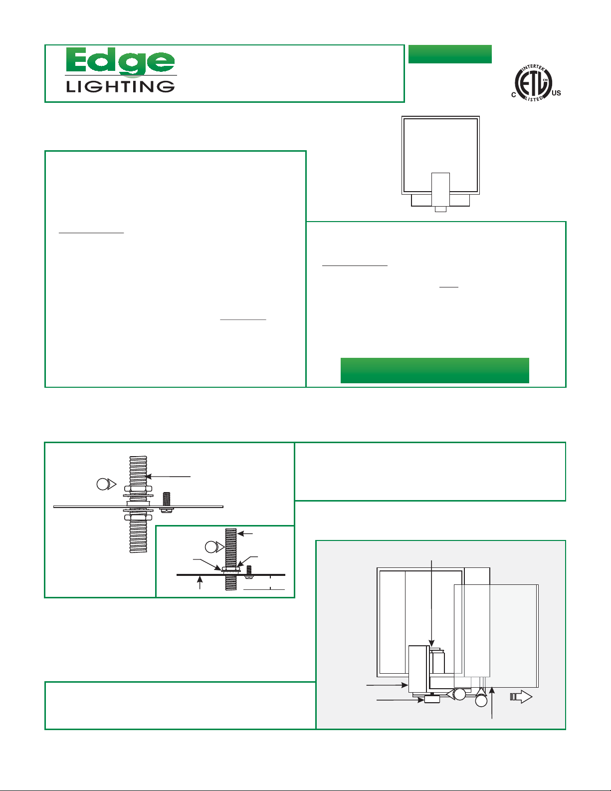
A
1
WASHER
3: While holding the glass cover, carefully loosen and remove
the thumb screw and "L" bracket.
CROSSBAR ASSEMBLY
NIPPLE
2
NUT
1/2"
CROSSBAR
1: Remove one nut and washer from the crossbar assembly.
2: Adjust the crossbar on the nipple so that 1/2" of the nipple is
exposed on one end. Secure the crossbar in place by
tightening the washer and nut.
B
"L" BRACKET
THUMB SCREW
SOCKET
3
4
4: Carefully slide the glass cover out.
GLASS COVER
1
Page 2
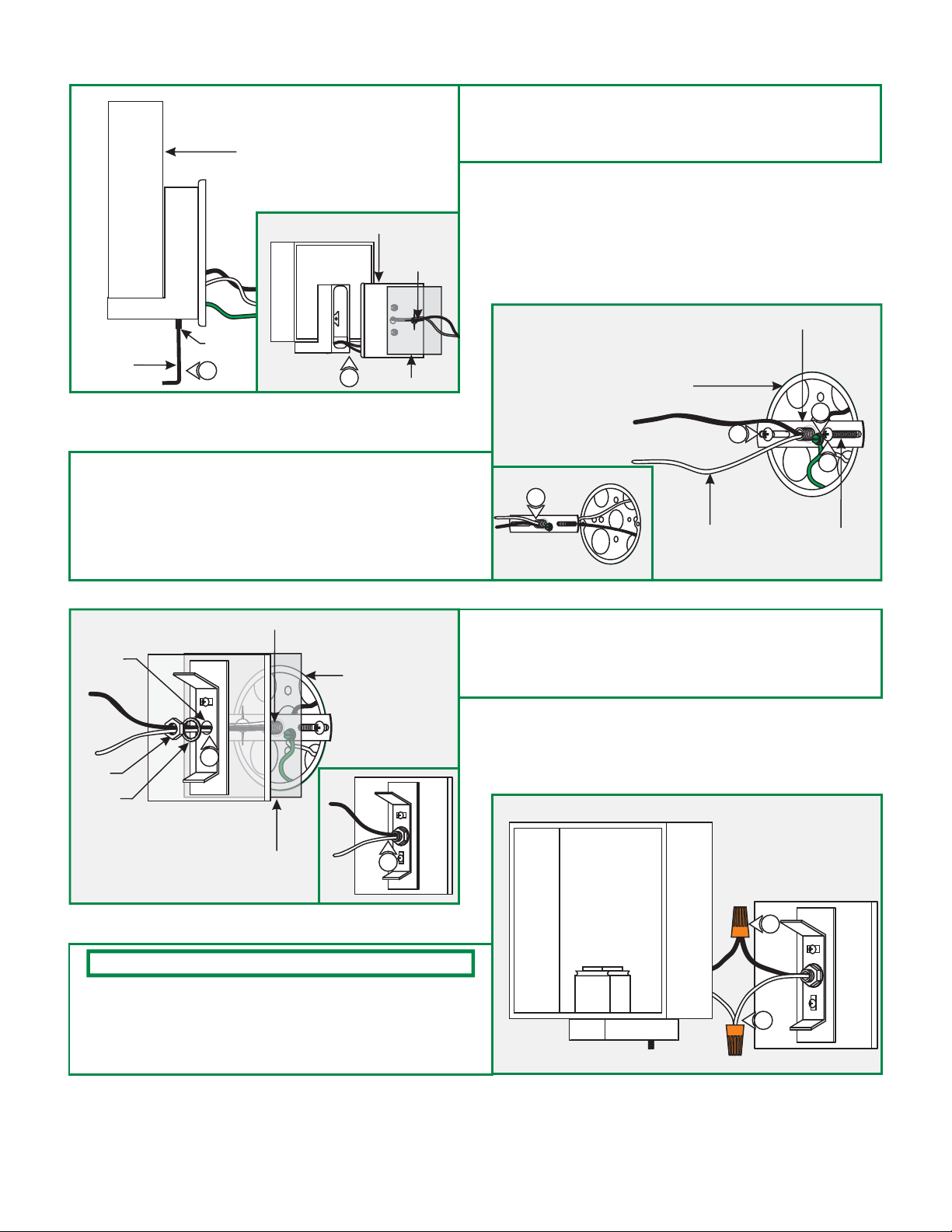
C
5: From the bottom of the fixture loosen
the M4 set screw with the 2mm Allen wrench .
(Do Not Remove)
FIXTURE
CANOPY
POWER
WIRES
M4 SET
2MM ALLEN
WRENCH
7: Feed the power wires through the crossbar assembly nipple.
8: Make sure the crossbar assembly is grounded in accordance
with local electrical codes.
9: Mount the crossbar assembly to the electrical box holes with
the two #8-32 screws provided.
SCREW
5
6
GASKET
6: Carefully, remove the canopy and gasket from the fixture.
D
ELECTRICAL BOX
7
POWER WIRE
CROSSBAR ASSEMBLY
8
9
9
#8-32 SCREW
E
CANOPY
CENTER
HOLE
NUT
LOCK
WASHER
NOTE: If necessary, trim the fixture wires.
12: While holding the fixture, connect the white fixture wire to
the neutral power wire with a wire nut.
13: Connect the black fixture wire to the hot power wire with a
wire nut.
CROSSBAR ASSEMBLY NIPPLE
ELECTRICAL BOX
10
GASKET
11
10: Feed the power wires through the gasket and canopy
center hole respectively.
11: Secure the canopy to the crossbar nipple with the lock
washer and nut.
F
13
12
2
Page 3

G
14: Place all wires and wire nut connections inside the fixture
body.
15: Slide the fixture body completely onto the canopy bracket
and tighten the M4 set screw on the bottom of the fixture
with the 2mm Allen wrench to secure.
15
H
14
16: Place the metal socket cover over the socket.
CAUTION:
lamping, disconnect the power to the fixture.
NOTE: Use only fingers and a soft cloth to install the lamps.
Use MAX 40 Watt Type T4, G9 Base, Bi-Pin
Halogen Lamp.
17: Push the lamp pins completely into the socket holes.
18: Place the lamp shield over the lamp.
19: Replace the glass cover onto front of the fixture. Replace
the "L" bracket and thumb screw to secure the glass cover
in place.
To reduce risk of a burn or electrical shock during
LAMP SHIELD
METAL SOCKET COVER
SOCKET
I
LAMP
18
17
16
J
SEALANT
20
"L" BRACKET
THUMB SCREW
20: For installation in wet location, caulk around the fixture
canopy with waterproof construction sealant.
19
GLASS COVER
3
 Loading...