

Page 1
904-MPORT-12VAC-02
© 2012 Edge Lighting. All Rights Reserved.
1718 W. Fullerton Ave
Chicago, IL 60614
Tel: 773-770-1195
Fax: 773-935-5613
www.edgelighting.com
info@edgelighting.com
MPORT-12VAC-_-SS
Installation Instructions for Miniport Round & Round Eye Lid LED
IMPORTANT SAFETY INFORMATION
- This product is ETL listed for indoor wet locations.
- WARNING: Fixture must be installed in accordance with
National and Local Electrical codes.
- Load cannot exceed the total wattage of the LED power
supply rating.
- This fixture must be installed by a licensed electrician.
- Use UL listed type UF underground cable when no conduit
is used to power the fixture(s).
- For outdoor installation, use outdoor rated electrical
boxes (minimum 1.5" deep), conduit feedings, and wire
nuts. For indoor installation use octagon electrical boxes.
- This instruction shows a typical installation.
SAVE THESE INSTRUCTIONS!
IMPORTANT INFORMATION
- Miniports are only powered by a 12VAC LED transformer
and are dimmable with an Electronic Low Voltage
Dimmer.
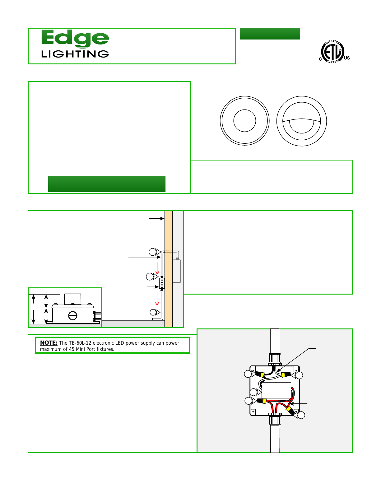
Outdoor Installation Using a LED Single Power Supply (TE-60L-12)
A
CONDUIT GOING TO
ELECTRICAL PANEL
1.47"
2.97"
1.5"
The TE-60L-12 electronic LED power supply can power
NOTE:
maximum of 45 Mini Port fixtures.
BUILDING WALL
2
120VAC
1
OUTDOOR
ELECTRICAL BOX
12VAC
3
GROUND
5: Connect the white LED power supply wire to 120 volt neutral
power wire with a wire nut.
6: Connect the black LED power supply wire to 120 volt hot
power wire with a wire nut.
7: Connect one 12 volt power supply (red wire) in parallel to
one wire going to each fixture electrical box with wire nuts.
Connect the other 12 volt power supply wire in parallel to the
other wire going to each fixture electrical box with wire nuts.
(See wiring diagram on page 4).
1: Install an outdoor electrical box onto the wall or post next to
the building to fit the LED power supply (TE-60L-12) and to
branch the power to all in ground electrical boxes
2: Install conduit and run 120 volt power wires from the panel
to the outdoor box.
3: Install conduit(s) from the outdoor electrical box to all in
ground fixture outdoor electrical boxes.
4: Run proper wire sizes from branching electrical box to all
fixture electrical boxes using the "Wire Size Chart" on page 3.
B
120 VOLT
WIRES (INPUT)
6
8
7
5
12 VOLT
WIRES (OUTPUT)
7
8: Place the LED power supply and wire nut connection inside
the electrical box and mount the box cover.
1
Page 2
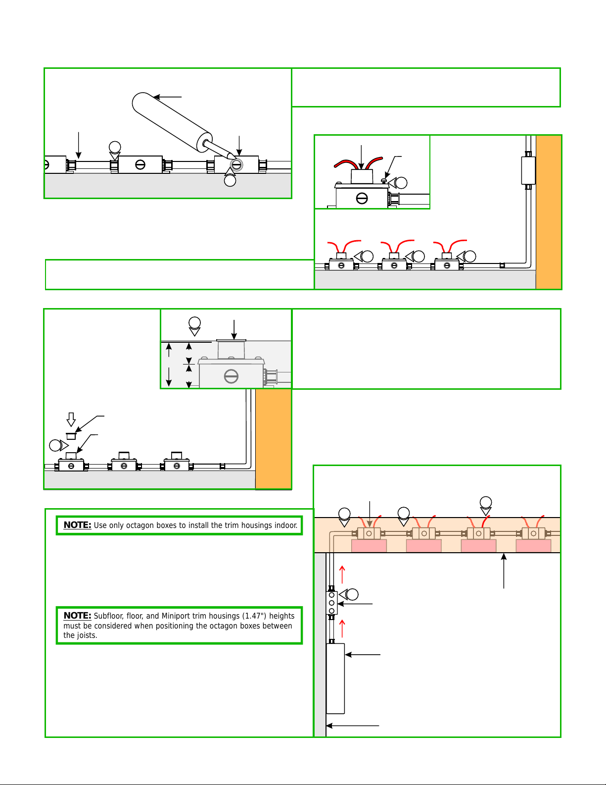
Outdoor Trim Housing Installation
C
WATER PROOF
SILICONE
OUTDOOR
CONDUIT
1
GROUND
2: Align and secure each trim housing to the electrical box holes
with the four #10-24 water sealant screws provided.
E
1.47"
2.97"
1.5"
OUTDOOR
ELECTRICAL BOX
PLASTIC CAP
4
1
CONCRETE
1: Caulk all areas of the outdoor electrical boxes and the
conduit connectors with a water proof silicone to prevent
water entering in the electrical boxes.
TRIM HOUSING
D
12VAC 12VAC 12VAC
2 2 2
3: Insert the provided plastic caps to all trim housings to
prevent particles and concrete debris from entering inside
the box.
4: Poor the concrete up to plastic cap and wait to dry.
5: Refer to the "Install the Trims" section.
#10-24
SCREW
2
GROUND
PLASTIC CAP
TRIM HOUSING
3
GROUND
NOTE: Use only octagon boxes to install the trim housings indoor.
1: Install an electrical box onto the wall or post next to the
panel to fit the LED power supply (TE-60L-12) and to branch
the power to all octagon electrical boxes.
2: Install conduit and run 120 volt power wires from the panel
to the branching electrical box.
NOTE:
Subfloor, floor, and Miniport trim housings (1.47") heights
must be considered when positioning the octagon boxes between
the joists.
3: Install conduit(s) from the branching electrical box to all
octagon fixture electrical boxes.
4: Run proper wire sizes from branching electrical box to all
fixture electrical boxes using the "Wire Size Chart" on page 3.
Indoor Installation Using a Single
LED Power Supply (TE-60L-12)
F
OCTAGON ELECTRICAL BOX
2
12VAC
1
120VAC
3
BRANCH ELECTRICAL BOX
PANEL
4
JOIST
5: Follow steps 5 through 8 on page 1 using drawing B to
connect the wires to the power supply.
WALL
2
Page 3

Indoor Trim Housing
Installation
G
12VAC
TRIM HOUSING
CONDUIT
#8-32
SCREW
1
12VAC 12VAC 12VAC
1
1: Align and secure the each trim housing to the octagon
electrical box holes with the two #8-32 screws (not
provided).
PLASTIC CAP
H
FLOOR
3
2: Insert the provided plastic caps to all trim housing to prevent
dust and debris from entering inside the box.
3: Finish the floor installation up to the plastic cap.
4: Refer to the "Install the Trims" section.
Wiring the Trims
I
TRIM
LED
DRIVER
2
TRIM
HOUSING
2
SUBFLOOR
JOIST
PLASTIC
CAP
3
NOTE:
nuts for power connection.
1: Remove the plastic caps.
2: Connect the brown driver wire to one low voltage wire
(either one) and the blue driver wire to the other low voltage
wire coming from the transformer with wire nuts.
3: Place all wire connections inside the electrical box and push
the trim completely into the trim housing opening.
4: Repeat steps 1 through 3 for other trims.
2
For outdoor installation, use water proof outdoor wire
1.47"
2.97"
1.5"
TRIM HOUSING
Each fixture contains an integrated LED lamp. Each
6
NOTE:
Miniport consumes 1 watt.
LOW VOLTAGE WIRE SIZE CHART
TRANSFORMER
WATTAGE
12V 60W
TE-60L-12
WIRE SIZE
FOR UP TO 13 FT
#14 AWG #12 AWG #10 AWG #8 AWG
WIRE SIZE
FOR 14-20 FT
WIRE SIZE
FOR 21-34 FT
WIRE SIZE
FOR 34-52 FT
3
Page 4

Indoor Installation without
the Trim Housing
J
1-3/4"
HOLE
SPRING CLIP
WASHER
2
SCREW
4
1: Remove the two "O" rings from the Miniport.
2: Install the provided spring clip on back of the Miniport with
the washers and screws.
3: Make a 1-3/4" circular hole where each Miniport is going to
be installed. (DRYWALL or the riser of the wood steps)
4
4: Connect the black driver wire to one low voltage wire and
TRIM
the white driver wire to the other low voltage wire coming
from the transformer with wire nuts.
5: Push the Miniport spring completely inside the cut out hole
5
TRIM
TRIM
1
"O" RING
so that the Miniport is secured in place.
K
MINI PORT EYELID TRIM
MUST BE ORIENTED IN THIS
MANNER TO WORK PROPERLY
NOTE: If installing eyelid Miniport to the walls next to stairs
place the trim in the downward position for proper lighting.
Overall Wiring Diagram
ELECTRONIC LOW
HOT
(BLACK)
120 VAC
NEUTRAL
(WHITE)
VOLTAGE DIMMER
YELLOW
120 VAC
WHITE
ELECTRONIC LED
12VAC TRANSFORMER
(TE-60L-12)
12VAC
WALL
STAIRS
LIGHT BEAM
MINIPORT
4
 Loading...