

Edge Lighting Micro Grazer Light Channel 7W or 4.4W 24V User Manual
904-LCMG7-24V-03
© 2013 Edge Lighting. All Rights Reserved.
1718 W. Fullerton Ave
Chicago, IL 60614
Tel: 773-770-1195
Fax: 773-935-5613
www.edgelighting.com
info@edgelighting.com
LCMG7-24V-_
Installation Instructions for Micro Grazer Light Channel 7W, 24V
IMPORTANT INFORMATION
- This instruction shows a typical installation.
SAVE THESE INSTRUCTIONS!
Install the Light Channel
A
CEILING
LIGHT
BEAMS
TEXTURED WALL
B
STUD
CEILING
LIGHT
BEAMS
ALL ON A 11°
TEXTURED W
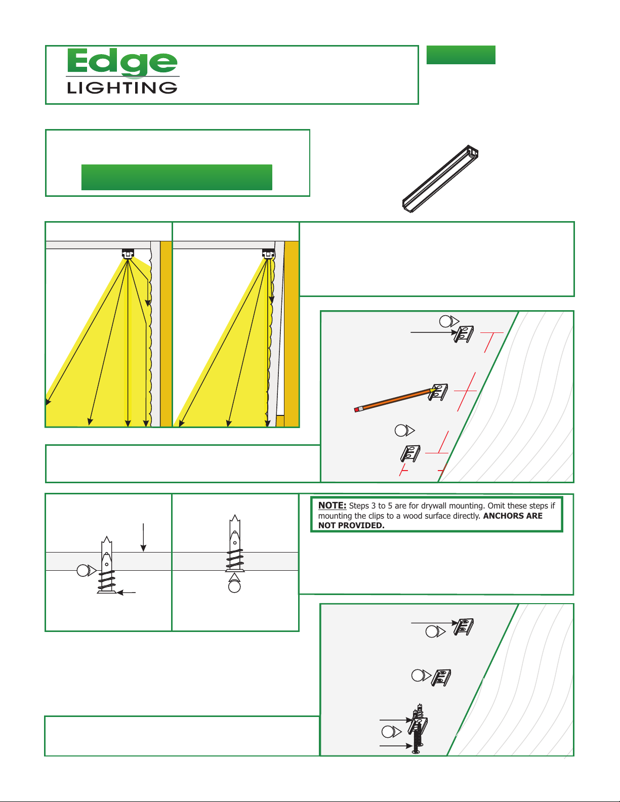
2: Place the clips on the surface every 1' (measure from the
the center slot of the mounting clip) and mark the screw
locations.
D
SURFACE
1: Choose one of the two options to install the Micro Grazer to
properly graze the textured wall.
Option A: Mount the Micro Grazer 3" to 6" away from
the straight textured wall.
Option B: Mount the Micro Grazer next to the textured wall
that is installed at an 11° angle.
C
STUD
CEILING
Steps 3 to 5 are for drywall mounting. Omit these steps if
NOTE:
mounting the clips to a wood surface directly. ANCHORS ARE
NOT PROVIDED.
MOUNTING
CLIP
2
3IN-6IN
2
1FT
1FT
TEXTURED WALL
3
ANCHOR
4
5: Line up the mounting clips to the anchors and secure it to
the anchors by tightening the two #8 screws to each
clip.
3: Tap the anchors onto the marked points up to the threaded
portion with a hammer.
4: Screw in the threaded portion of the anchors with a Phillips
screwdriver.
E
ANCHOR
#8 SCREW
MOUNTING
CLIP
5
5
5
CEILING
TEXTURED WALL
1

F
MOUNTING
6: Snap each Light Channel into the spring clips.
CLIP
6
LIGHT
CHANNEL
CEILING
TEXTURED WALL
NOTE: Multiple light channel can be connected together directly
by connecting male end of one to the female end of the other
one, or by using the flexible connectors up to a maximum of
10 feet.
7: Carefully, connect light channel male end to light channel
female end, or refer to the flexible connector instruction.
H
POWER CORD
CORD GRIP
POWER
END CAP
LIGHT
CHANNEL
SCREW
8
10
POWER
CORD
9
CORD GRIP
G
ADDITIONAL
LIGHT CHANNEL
7
LIGHT
CHANNEL
LIGHT CHANNEL CONNECTION
USING FLEXIBLE CONNECTOR
DIRECT LIGHT CHANNEL CONNECTION
FROM ONE END TO ANOTHER END
NOTE: The power feed cable can be mounted to either the
female or male end of the channel.
8: Remove the two bottom screws (closest to the mounted
surface) of the selected power end cap.
9: Place the male end of the power cord in the cord grip if
connecting to the female end of the light channel, or place
the female end of the power cord in the cord grip if
connecting to the male end of the light channel.
10: Push the cord completely into the light channel power end
cap pins and secure the cord grip to the light channel by
tightening the two screws (provided with cord grip) through
the cord grip into the light channel power end cap.
11: Cut the other end of the power cord (male or female) and
discard it. Strip the wire end for connecting it to the power
supply.
12: Follow the instructions provided with the power supply to
power up the light channel.
I
LIGHT CHANNEL
POWER CORD
11
CUT
11
2
 Loading...