

Page 1
1718 W. Fullerton Ave
Chicago, IL 60614
Tel: 773-770-1195
Fax: 773-935-5613
www.edgelighting.com
© 2012 Edge Lighting. All Rights Reserved.
info@edgelighting.com
Installation Instructions for Lyra Suspension
IMPORTANT SAFETY INSTRUCTIONS
To reduce the risk of fire, electrical shock, exposure to
excessive UV radiation, or injury to persons:
- Use this fixture indoors only.
- Do not look directly at the lamp while the fixture is on.
- RISK OF FIRE: Use only the type of lamp and maximum
wattage indicated in this instruction manual.
- Never cover the halogen lamp with anything other than a
lamp shade provided by Edge Lighting and never place
flammable material close to the fixture.
- Never turn the fixture on and off by connecting and
disconnecting the halogen lamp.
- Do not touch the fixture head, shade or lamp shield while
the fixture is on. These surfaces may be VERY HOT.
- Do not touch lamp at anytime. Use a soft cloth instead as oil
from skin may damage lamp.
- It is normal for a new halogen lamp to produce minor
smoke when first turned on.
- Turn power off and allow to cool before replacing lamp.
IMPORTANT INFORMATION
- This product is ETL listed for indoor dry locations.
- This product is ceiling mounted only.
- This product can mount to either a 4" square electrical box
with round plaster ring or an octagon electrical box.
- Only the MR16 Lamps can be dimmed with a low voltage
electronic dimmer.
LYRA-_
SAVE THESE INSTRUCTIONS!
904-LYRA-01
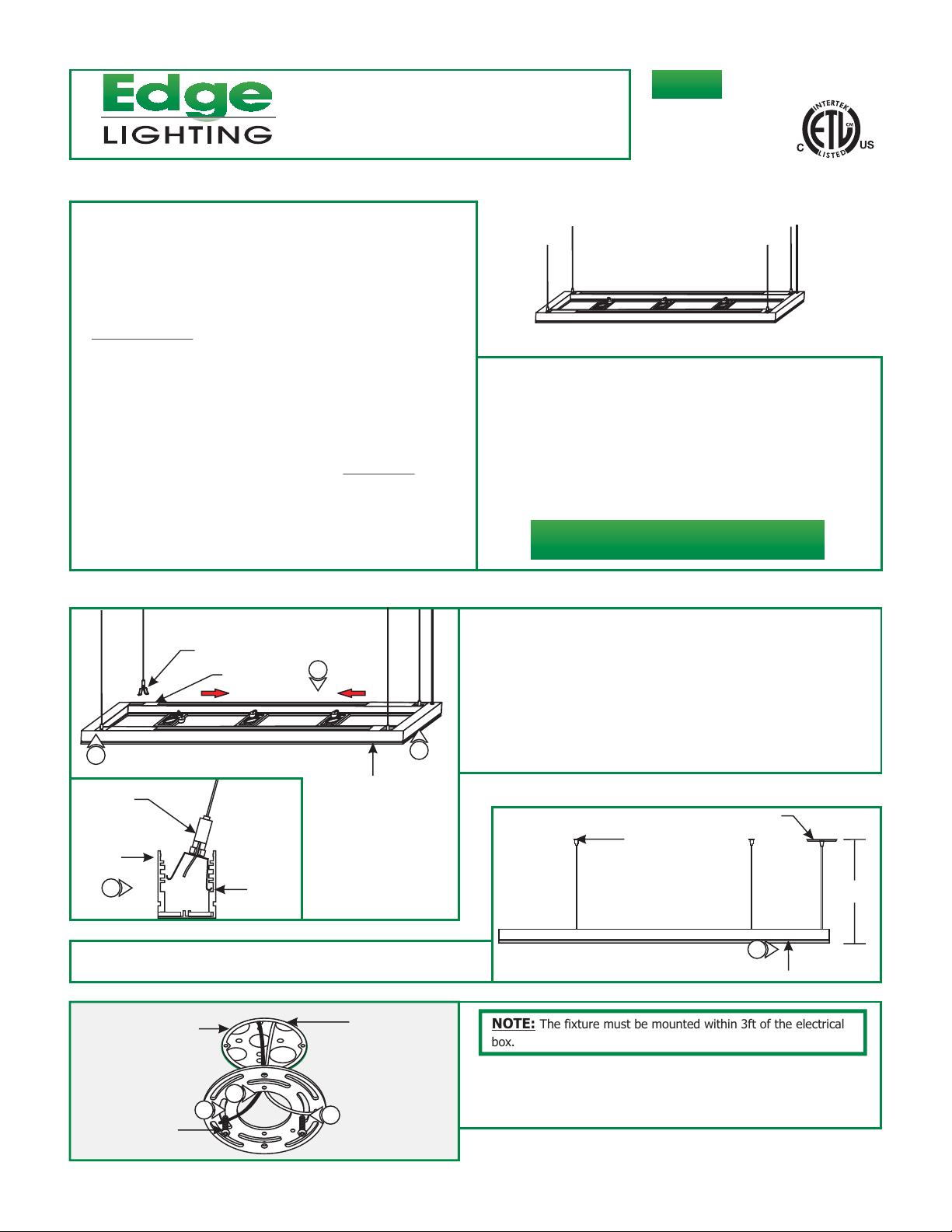
Install the Fixture
A
SUPPORT CLIP
WIRE COVER
3
SUPPORT
CLIP
FIXTURE
FRAME
3
4: Determine the desired fixture height (H), from the bottom of
the fixture frame to the top the canopy and standoffs.
C
ELECTRICAL BOX
BOTTOM
SLOT
1
3
FIXTURE
FRAME
CROSSBAR
1: Carefully slide the four wire covers on top of the fixture
towards the center of the fixture frame.
2: Insert the curved end of the support clip to the bottom
slot of the fixture frame and then squeeze the other end to
safely secure into the bottom slot.
3: Install the remaining support clip to each corner of the
fixture frame, and slide wire covers back in place.
B
NOTE: The fixture must be mounted within 3ft of the electrical
box.
STANDOFF
CANOPY
H
4
FIXTURE FRAME
#8-32 SCREW
5: Feed the power wires through the crossbar center cutout.
5
6
6
6: Secure the crossbar to the electrical box with the provided
two #8-32 screws.
1
Page 2
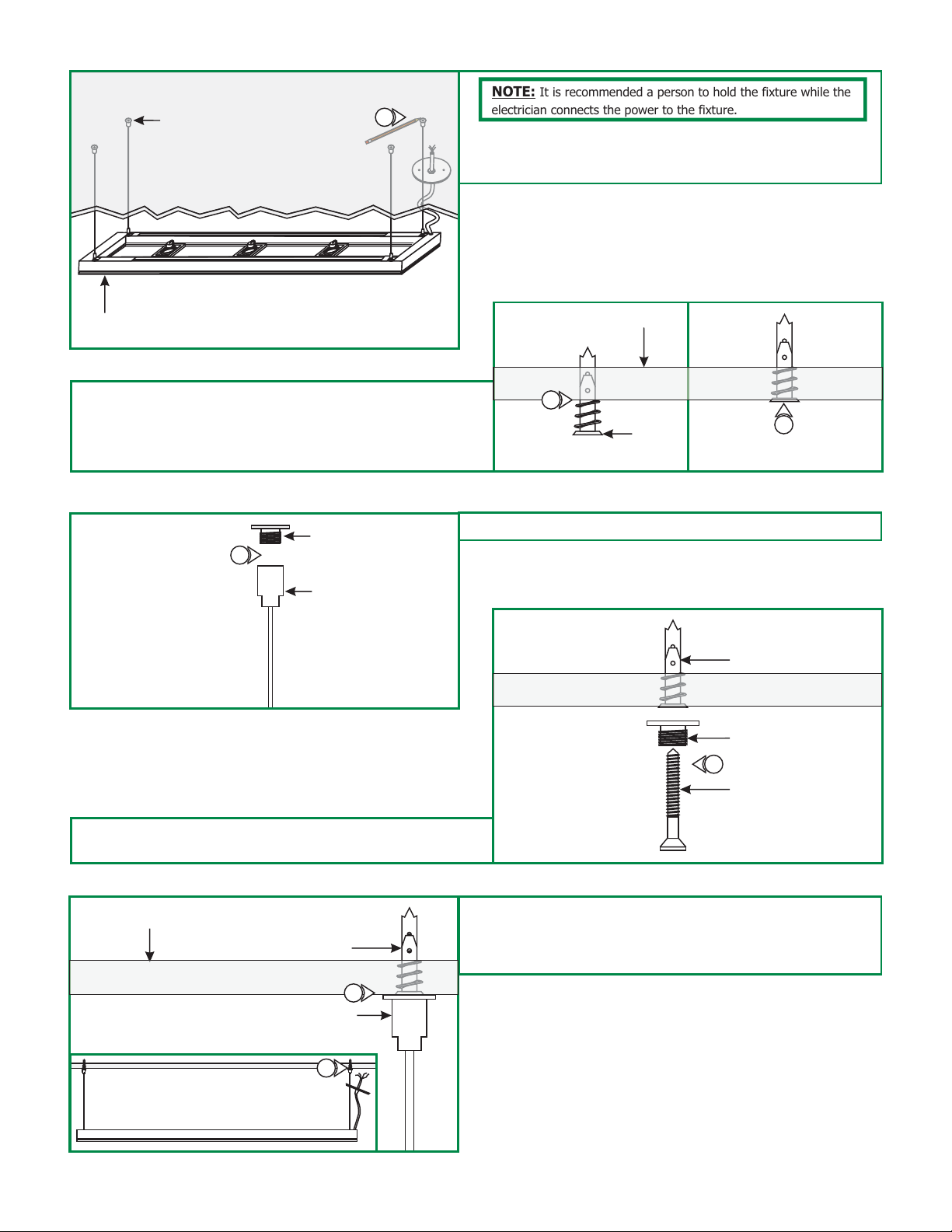
D
STANDOFF
CEILING CUTAWAY
7
NOTE: It is recommended a person to hold the fixture while the
electrician connects the power to the fixture.
7: While one person holds the fixture, the other person marks
the standoff location. (Must be within 3ft of electrical
location).
FIXTURE
FRAME
8: Tap the anchors onto the marked locations up to the
threaded portion with a hammer.
9: Screw in the threaded portion of the anchors with a Phillips
screwdriver.
F
10
CAP
STANDOFF
E
8
10: Remove the caps off each standoff.
CEILING
ANCHOR
G
11
9
ANCHOR
CAP
#8 SCREW
11: Feed the #8 screw through the cap and tighten the #8
screw completely into the anchor.
H
CEILING
ANCHOR
12
STANDOFF
13
12: Carefully, tighten the standoff completely onto the
threaded nipple.
13: Repeat steps 10 through 11 for the remaining standoffs.
2
Page 3

I
14: Slide the fixture frame up and down by pushing the tab on
each support clip until desired height is achieved. Release
the tab to lock the aircraft cable in place.
15: Trim off excess aircraft cable with a sharp cutter.
FIXTURE
SUPPORT
CLIP TAB
FIXTURE
FRAME
16: Loosen the cord strain relief on the canopy and push the
excess clear cord into the canopy.
17: Leave 8" of the clear cord exposed behind the canopy for
power connection. Tighten the cord strain relief on the
canopy to lock the clear cord in place.
18:
Trim off the excess clear cord.
19: From the end of the clear cord, strip 4" of the outer
insulation using a sharp knife. Make sure not to nick the
inner wires. Trim off the cut out insulation.
K
#8-32 SCREW
CROSSBAR
14
15
20
21
FRAME
16
CANOPY
17
19
4"
8"
17
CORD
J
CORD
CORD STRAIN
RELIEF
CANOPY
NOTE:
20: Place all wires and wire nuts connections inside electrical
box.
For wiring details refer to page 4.
CANOPY
CAUTION: To reduce risk of a burn or electrical shock during
lamping, disconnect the power to the fixture.
Use MAX 50 Watt, Type MR16 Front Glass Cover
Halogen Lamp, For Each Socket.
1: Place a lamp and lens or louver (optional) into each fixture
ring.
2: Replace and tighten the lamp holder rings.
3: Align and push each socket completely onto lamp pins.
21: Align the canopy holes to the crossbar center holes and
secure using the two #8-32 screws.
Install the Lamp
L
LAMP
HOLDER
RING
SOCKET
FIXTURE
RING
SOCKET
3
LAMP
2
LAMP
LOUVER
1
3
Page 4

SOCKET
CAUTION: To reduce risk of a burn or electrical shock during
lamping, disconnect the power to the fixture.
LAMP
Wiring Diagram
4
Use MAX 24 Watt Type T5, Linear
Fluorescent Lamp For LYRA-26-SA.
Use MAX 39 Watt Type T5, Linear
Fluorescent Lamp For LYRA-48-SA & LYRA-96-SA.
MAX 54 Watt Type T5, Linear
Use
Fluorescent Lamp For LYRA-60-XX & LYRA-120-XX.
4: Line up the lamp pins on both socket ends.
5: Insert the lamp pins all the way into the sockets and turn
the lamp to lock it in place. Repeat this step for the other
6
lamp.
6: Repeats steps 1 & 2 for the remaining lamps.
300W ELECTRONIC LOW
VOLTAGE DIMMER WITH
NEUTRAL CONNECTION
NEUTRAL 120VAC
HOT 120VAC
ON/OFF SWITCH
HOT
GROUND
HOT
GREEN WIRE
BROWN WIRE
(FLUORESCENT)
BLUE WIRE
(HALOGEN)
CLEAR WIRE
(NEUTRAL)
FIXTURE WIRES
4
 Loading...