

Page 1
1718 W. Fullerton Ave
Chicago, IL 60614
Tel: 773-770-1195
Fax: 773-935-5613
www.edgelighting.com
© 2013 Edge Lighting. All Rights Reserved.
info@edgelighting.com
Installation Instructions for Light Channel Trim 1.6
IMPORTANT INFORMATION
- This fixture is wall or ceiling mount.
- This instruction shows a typical installation.
- If modifying channel length, please see “Section
Three: Modifying Channel Length” on Page 4 before
installation.
SAVE THESE INSTRUCTIONS!
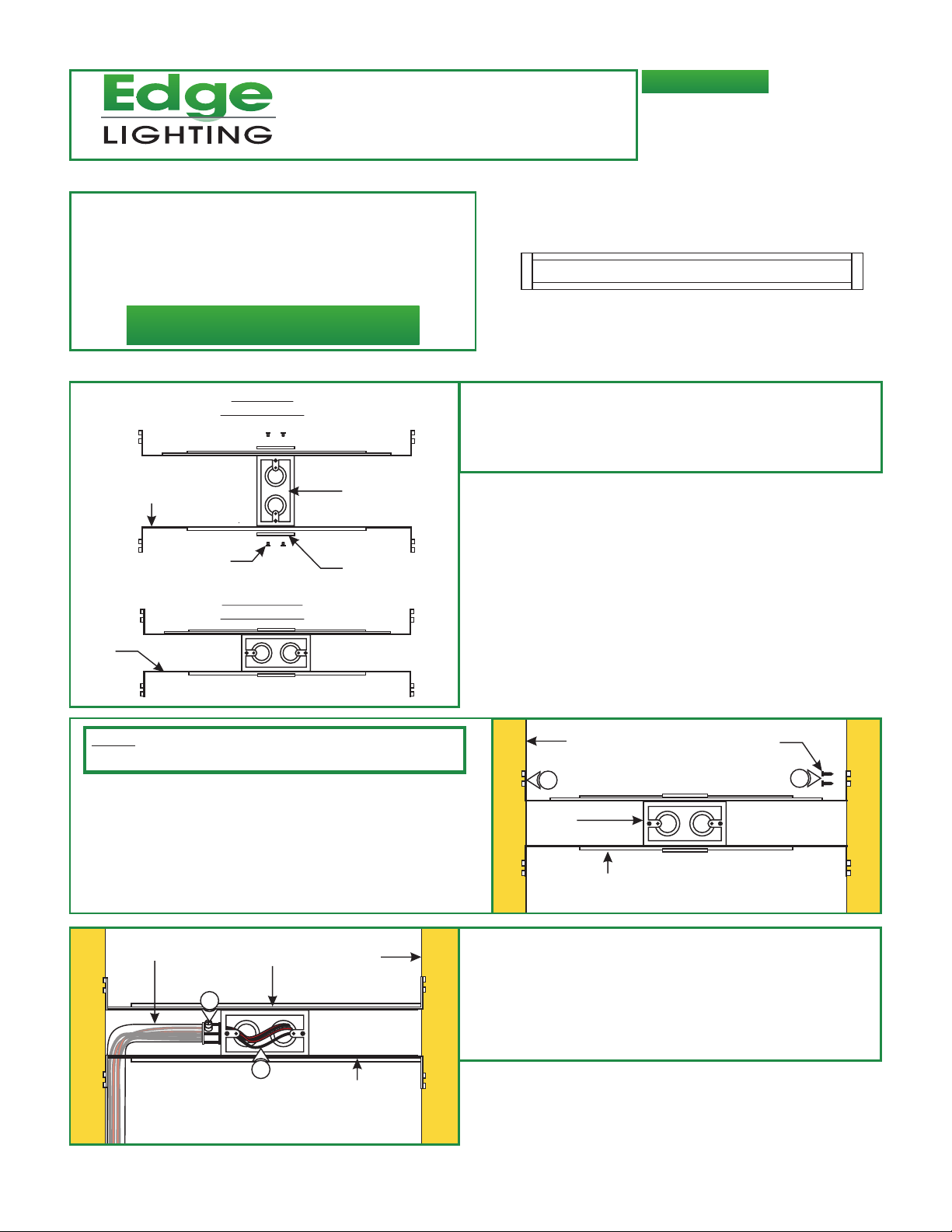
Section One: Installing The Channel
A
ADJUSTABLE
MOUNTING BAR
VERTICAL
ORIENTATION
JUNCTION
BOX
1
: Mount each adjustable mounting bar to one side of the
junction box (mounts to any side of the housing
depending on the orientation of the channel) and secure
them with the mounting brackets and two Phillips screws
provided.
LCT1.6-5WDC-_
904-LCT-1_6_02
PHILLIPS
SCREW
HORIZONTAL
ORIENTATION
JUNCTION
BOX
MOUNTING
BRACKET
NOTE: The adjustable mounting bars mount to studs that are
spaced 13" to 24" apart.
2: Select the location between the two studs for the junction
box to be mounted.
3: Place the adjustable mounting bars between the studs.
4: Make sure the lips on the adjustable mounting bars are
against the studs. Secure the adjustable bars to the studs
with the eight #8 screws.
C
CONDUIT
JUNCTION BOX
5
STUD
B
STUD
3
JUNCTION
BOX
ADJUSTABLE
MOUNTING BAR
#8 SCREW
4
5: Remove a knockout to install the power line conduit.
6: Install the conduit and run the low voltage 24V DC power
wires coming from the remote power supply to the
junction box.
7: Refer to the instruction provided with the power supply
along with the wiring diagram for proper wiring.
6
ADJUSTABLE
MOUNTING BAR
1
Page 2
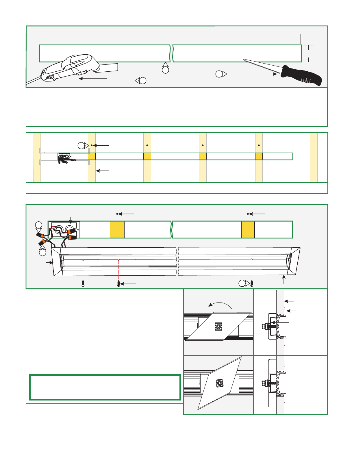
D
LENGTH OF
THE CHANNEL
DRYWALL
2.25"
DREMEL
MULTI-MAX
8
9
9
6" FIXED
JAB SAW
8: Mark the area where the channel will be located on the drywall.
9: Cut out the marked area(s) and install the drywall, using a "Dremel Multi-Max" with the "wood & drywall" cutting bit or a 6"
Fixed Jab Saw.
10: Install & finish drywall.
E
11
11: Mark the location of the studs to the drywall for future reference.
F
12
POWER FEED
JUNCTION BOX
MARKING
STUD
MARKING MARKING
13
ENDCAP
#6 SCREW
12: Connect the red power supply (24VDC+) wires to each red
power wire with a wire nut.
13: Connect the black power supply (24VDC-) wires to each
black power wire with a wire nut.
14: Place the wire nut connections inside junction box.
15: Using the marked locations on the drywall, carefully make a
hole to channel using the provided square drill with counter
sink bit.
16: Secure the channel to the stud and the junction box with the
#6 drywall screws using the provided square recess bit.
NOTE: If channel does not line up with a stud, use the provided
constraint clip kit to install to the drywall. Refer to diagram to the
right for reference. For alternate installation see “Section Two:
Alternate Installation w/Uneven Studs” on Page 4.
BACK
VIEW
TIGHTEN SCREW TO LOCK
CLIP INTO PLACE
16
SIDE
VIEW
CHANNEL
CONSTRAINT
CLIP (CONSISTS
OF A SCREW,
BASE, WING CLIP,
CAGE NUT,
& HEX NUT)
AS SCREW IS
TIGHTENED,
CAGE NUT LOCKS
INTO PLACE
CAUSING
THE WING CLIP TO
SECURE TO
THE DRYWALL.
DRYWALL
CHANNEL
2
Page 3

G
SOFT STRIP
17
18
POWER
CONNECTOR
17: Push the male connector of the Soft Strip into the female connector of the power connector.
18: Carefully remove the backing from the LED soft strip, make sure not to remove the tape from the soft strip. Firmly press down
the adhesive portion of the soft strip onto the channel surface while removing the rest of the backing, making sure there are
no air bubbles that can cause surface irregularities. Ensure the entire length of the channel is covered with Soft Strip to avoid
unlit areas.
H
PAPER
BACKING
CHANNEL
19
END CAP
LED STRIP
CHANNEL
OPTIONAL:
19: Trim excess LED strip at cut point.
20: If channel length has been modified as per the “Section
Three: Modifying Channel Length” section on Page 4,
insert excess LED strip into slot cut between the channel
and end cap.
I
20
LED STRIP
LENS FULLY
SEATED
21: Snap the lens into the channel and make sure it is fully
seated along the length of the channel opening.
LENS NOT
FULLY SEATED
LENS
LENS
CHANNEL
CHANNEL
3
Page 4

Section Two: Alternate Installation w/Uneven Studs
J
1 1
1: Mark the wall where channel mounting holes are located along the channel opening.
K
4 4
3 3
2: Cut 1" thick by 3" long sections of 2x4 to use as support bars.
3: Place the cut support bars through and behind the drywall at the marked mounting hole location.
4: Secure the support bars through drywall using two #6 drywall screws. Continue the installation as per Section One, Step 8.
Section Three: Modifying Channel Length
: If desired fixture length is less than the provided channel
L
CHANNEL
2
END CAP
#4-40
SCREWS
1
length, remove one channel end cap by loosening two #4-40
screws with the provided Torx drive.
2: Cut channel to desired length.
CHANNEL
1
END CAP
#4-40
SCREWS
3 4
3: Slightly grind off (~1/16") of the bottom of the channel. This
will allow excess LED strip to pass through after the end cap
is reinstalled.
4: Reinstall the channel end cap by replacing and tightening the
two #4-40 screws with the provided Torx drive.
4
 Loading...