

Page 1

904-LCSM-24V-RGB-01
© 2013 Edge Lighting. All Rights Reserved.
1718 W. Fullerton Ave
Chicago, IL 60614
Tel: 773-770-1195
Fax: 773-935-5613
www.edgelighting.com
info@edgelighting.com
LCSM-24V-_-RGB-_
Installation Instructions for Surface Mount Light Channel RGB, 24VDC
IMPORTANT INFORMATION
- This instruction shows a typical installation.
SAVE THESE INSTRUCTIONS!
Install the Light Channel
A
2 FOOT 2 FOOT
1
MOUNTING CLIP
Steps 3 to 5 are for drywall mounting. Omit these steps if
NOTE:
mounting the clips to a wood surface directly. ANCHORS ARE
NOT PROVIDED.
3: Tap the anchors onto the marked points up to the threaded
portion with a hammer.
4: Screw in the threaded portion of the anchors with a Phillips
screwdriver.
C
ANCHOR
2
SURFACE
SURFACE
1: Determine the location for the Light Channel.
2: Place the clips on the surface every 2' (measure from the
the center slot of the mounting clip) and mark the screw
locations.
B
WALL
3
ANCHOR
5: Line up the mounting clips to the anchors and secure it to
the anchors by tightening the two #8-32 screws to each
clip.
4
SCREW
5
MOUNTING CLIP
6: Snap each Light Channel into the spring clips.
D
6
LIGHT CHANNEL
SURFACE
MOUNTING CLIP
1
Page 2
E
LIGHT CHANNEL
7
LIGHT CHANNEL CONNECTION
USING FLEXIBLE CONNECTOR
DIRECT LIGHT CHANNEL CONNECTION
FROM ONE END TO ANOTHER END
ADDITIONAL
LIGHT CHANNEL
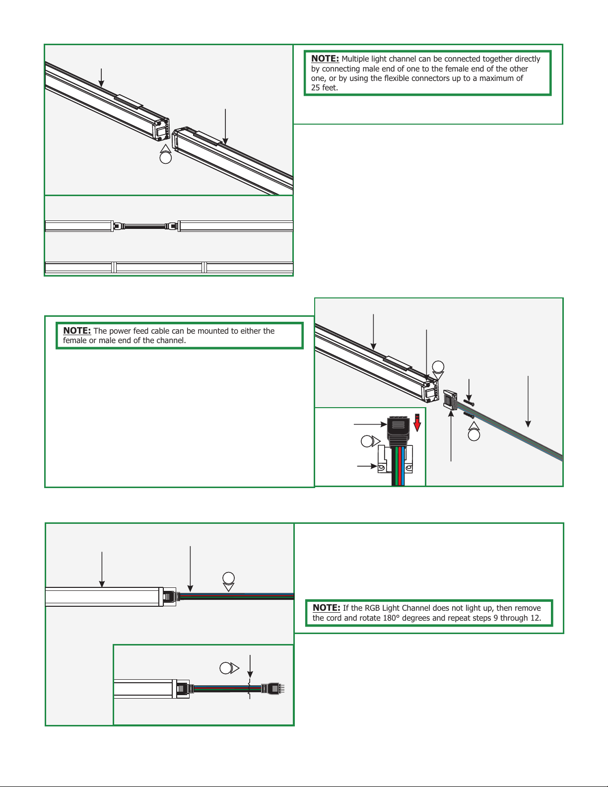
NOTE: Multiple light channel can be connected together directly
by connecting male end of one to the female end of the other
one, or by using the flexible connectors up to a maximum of
25 feet.
7: Carefully, connect light channel male end to light channel
female end, or refer to the flexible connector instruction.
NOTE: The power feed cable can be mounted to either the
female or male end of the channel.
8: Remove the two bottom screws (closest to the mounted
surface) of the selected power end cap.
9: Place the male end of the power cord in the cord grip if
connecting to the female end of the light channel or place
the female end of the power cord in the cord grip if
connecting to the male end of the light channel.
10: Push the cord completely into the light channel power end
cap pins and secure the cord grip to the light channel by
tightening the two screws (provided with cord grip) through
the cord grip into the light channel power end cap.
I
LIGHT CHANNEL
POWER CORD
11
F
CORD GRIP
LIGHT CHANNEL
POWER
CORD
POWER END CAP
10
SCREW
9
CORD GRIP
POWER CORD
9
11: Cut the other end of the power cord (male or female) and
discard it. Strip the wire end for connecting it to the power
supply.
12: Follow the instructions provided with the RGB power supply
to power up the light channel.
11
NOTE: If the RGB Light Channel does not light up, then remove
the cord and rotate 180° degrees and repeat steps 9 through 12.
CUT
2
Page 3

GENERAL WIRING DIAGRAM
CDP
CONTROLLER
DO NOT
USE
-BLACK
+RED
VDC-
EXT in-
EXT in+
DMX in +
DMX in -
DMX in
shield
LEDSync
out+
LEDSync
DO NOT
USE
DMX CABLE
(BELDEN #9841)
24VDC
+ -
POWER SUPPLY
N L
LINE
NEUTRAL
HOT
CONTROLLER
POWER SUPPLY
24VDC
+ RED
- BLACK
VDC+
LEDSync
out shield
out-
N
L
120VAC
SURFACE MOUNT
VDC+
VDC-
Ext in-
Ext in+
DMX in +
DMX in -
DMX in shield
LedSync thru+
LedSync thru-
LedSync shield
M
DRIVER
LED supply +
Group 1 -
Group 2 -
Group 3 -
Group 4 -
LIGHT CHANNEL RGB
3
 Loading...