

Page 1

1718 W. Fullerton Ave
Chicago, IL 60614
Tel: 773-770-1195
Fax: 773-935-5613
www.edgelighting.com
© 2013 Edge Lighting. All Rights Reserved.
info@edgelighting.com
Installation Instructions for Millwork Light Channel
IMPORTANT INFORMATION
- This instruction shows a typical installation.
- Per NEC Article 410.16(A)(1)(3) & 410.16(C)(5). Approved
for Closet Storage Areas.
SAVE THESE INSTRUCTIONS!
Install the Light Channel
LCMW-12V-_
904-LCMW-03
A
1 3/8"
FOR
CORD
5/8"
CUT
DEPTH
7/8" CUT
NOTE:
connected together with the flexible connectors. Refer to the
instructions provided with the flexible connectors.
Multiple light channels up to total of 25 feet long can be
CHANNEL
LENGTH
WOOD
MITER CUT
7/8" WIDE
1: Determine the location of the Millwork Light Channel on the
wood.
NOTE:
3/4" thick wood. The cut out slot must be 7/8" wide and 5/8"
deep. Add 1-3/8" to the length of the channel to accommodate
the power cord spacing.
The Millwork Light Channel needs to be installed onto a
B
LIGHT CHANNEL
FLEXIBLE
CONNECTOR
ADDITIONAL
LIGHT CHANNEL
C
SCREW
FLEXIBLE
CONNECTOR
POWER FEED
CONNECTOR
2
DECORATIVE
CAP
3
LIGHT CHANNEL
END CAP
POWER FEED
CONNECTOR
POWER FEED
WIRES
SCREW
NOTE:
female or male end of the channel.
The power feed cable can be mounted to either the
2: Remove the two screws on the bottom of the light channel
(not the screws holding the decorative cap).
3: Place the male end of the power cord in the cord grip if
LIGHT
CHANNEL
connecting to the female end of the light channel, or place
the female end of the power cord in the cord grip if
connecting to the male end of the light channel.
4: Push the cord completely into the light channel power end
4
cap pins and secure the cord grip to the light channel by
tightening the two screws (provided with cord grip) through
the cord grip into the light channel power end cap.
1
Page 2
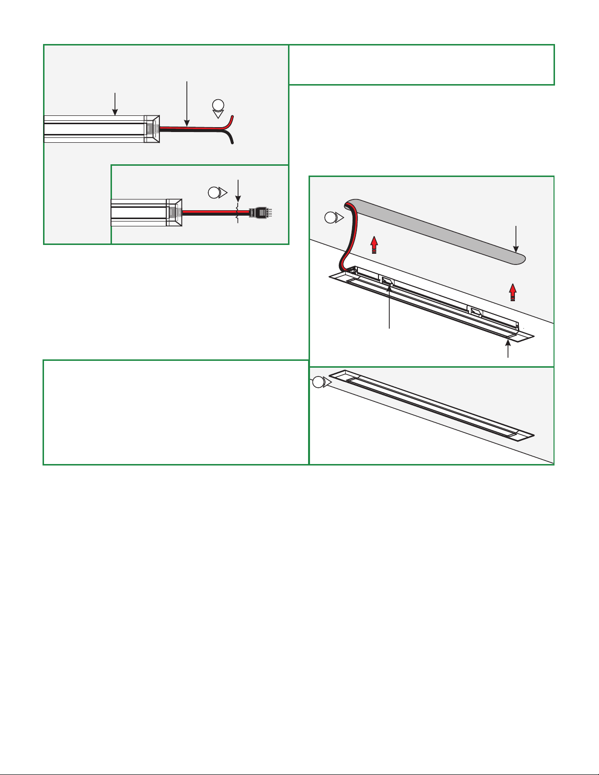
D
LIGHT CHANNEL
POWER CORD
5: Cut the other end of the power cord (male or female) and
discard it. Strip the wire end for connecting it to the power
supply.
5
CUT
5
E
6: Drill one end of the slot with 7/32 bit to run the light channel
wire.
7: Feed the wires through the hole and snap the light channel
into the slot, make sure all clips are tight. If necessary slide
the mounting clip to the appropriate area.
8: Follow the instructions provided with the power supply to
power up the light channel.
7
MOUNTING PLATE
7
SLOT
LIGHT CHANNEL
2
 Loading...