

Page 1
© 2013 Edge Lighting. All Rights Reserved.
Installation Instructions for Light Channel45°
IMPORTANT INFORMATION
- - 45 degree channel comes 12" to 120" long in a single
piece. Multiple 45 degree channels can be connected
together in series or parallel by connecting the 8ft pigtail
wires. These wires are rated for CLASS 2 (through the
wall) installation. Maximum 25' of the 45 degree channels
could be connect together when TEB-75L-24DC (Electronic
low voltage dimming) power supply is used, or 40' if the
PSB-96W-010-24VDC (0-10 dimming) is used.
This instruction shows typical installation.
SAVE THESE INSTRUCTIONS!
Install the Light Channel
1718 W. Fullerton Ave
Chicago, IL 60614
Tel: 773-770-1195
Fax: 773-935-5613
www.edgelighting.com
info@edgelighting.com
LC45-24V-_
LC45C-24V-_
904-LC45-24V-01
A
20"
AWAY
(TYP)
1
MOUNTING CLIP
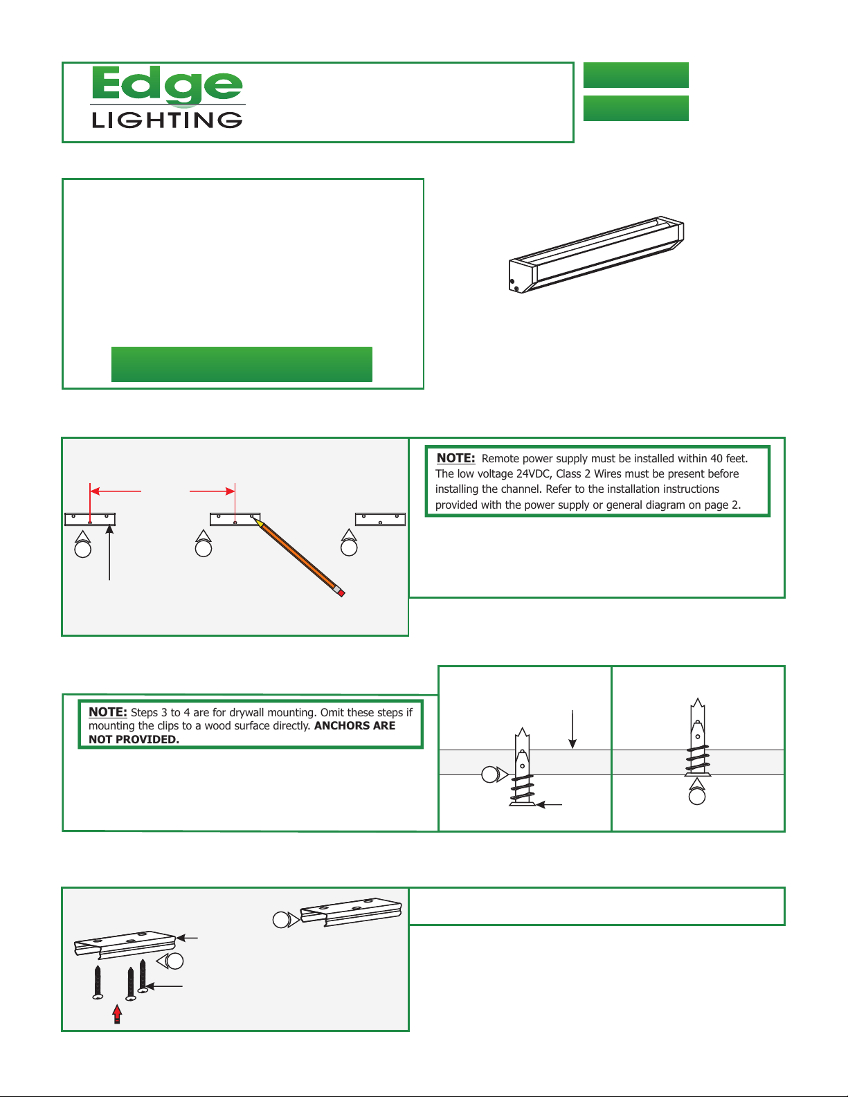
NOTE:
Steps 3 to 4 are for drywall mounting. Omit these steps if
mounting the clips to a wood surface directly. ANCHORS ARE
NOT PROVIDED.
3: Tap the anchors onto the marked points up to the threaded
portion with a hammer.
4: Screw in the threaded portion of the anchors with a Phillips
screwdriver.
2
WOOD
2
NOTE: Remote power supply must be installed within 40 feet.
The low voltage 24VDC, Class 2 Wires must be present before
installing the channel. Refer to the installation instructions
provided with the power supply or general diagram on page 2.
1: Determine the location for the Light Channel.
2: Place the clips on the surface every 20" (measure from the
the center slot of the mounting clip) and mark the screw
locations.
B
SURFACE
3
ANCHOR
4
C
5
#6 SCREW
MOUNTING
CLIP
5: Line up the mounting clips to the anchors and secure it to
5
the anchors by tightening the three #6 screws to each clip.
1
Page 2
D
MOUNTING CLIP
CHANNEL
6
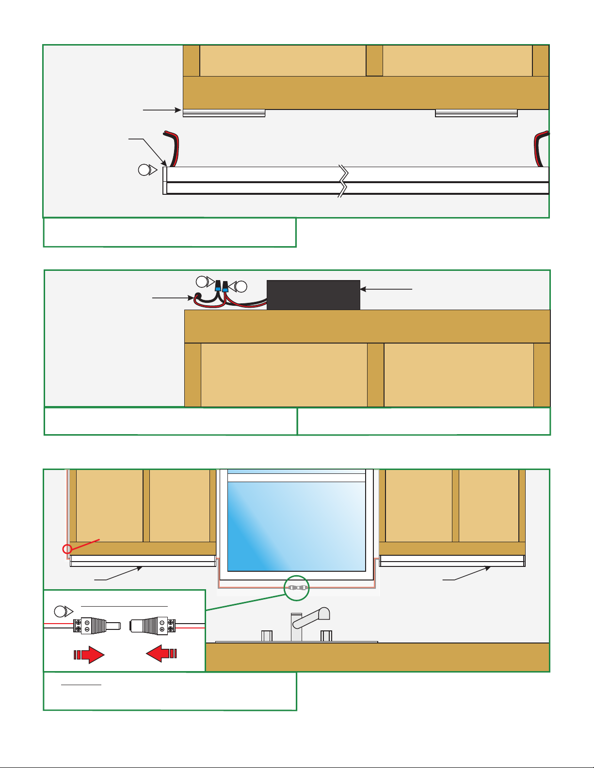
6: Choose the cord on one end of the channel that is the
closest to the class 2 wiring.
E
CLASS 2 POWER
SUPPLY WIRES
BOTTOM OF CABINET
8
TOP OF CABINET
7
POWER SUPPLY
(WITHIN 40FT)
7: Connect the red power supply (24VDC+) wire to red strip
wire with a wire nut inside the electrical box.
F
WIRES TO
POWER SUPPLY
CONNECT CHANNEL TOGETHER
CHANNEL 1
JOINING CONNECTOR
9
9: Optional: If power feeding one channel from the other,
then wire the male & female connectors provided. Connect
the red wires to "+" & black wires to "-" terminals.
8: Connect the black power supply (24VDC+) wire to black
strip wire with a wire nut inside the cabinet.
CHANNEL 2
WIRING IN WALL
2
Page 3

G
MOUNTING CLIP
BOTTOM OF CABINET
CHANNEL
STAGGER WIRE
AND TAPE
10
10: Cut the unused cord staggered leaving 2" exposed. Wrap
the end of the unused cord with electrical tape.
H
MOUNTING CLIP
CHANNEL
BOTTOM OF CABINET
10
11
11: Snap each Light Channel properly into the mounting clips.
GENERAL WIRING DIAGRAM
LIGHTOLIER:
INPUT
120VAC
BLACK (HOT)
ZP600FAM120
CONTROLLER
WHITE (NEUTRAL)
GND
RED 120VAC (HOT)
PURPLE 1-10V
GRAY 1-10V
PSB-96W-010-24VDC
input 120VAC
WH (N)
BK (L)
input 0-10V
PUR
GRY
DIMMING
RED (24VDC+)
BLUE (RETURN-)
YELLOW (DIM RETURN-)
24VDC
RED 24VDC+
BLACK 24VDC-
45° CHANNEL
3
 Loading...