

Page 1
© 2012 Edge Lighting. All Rights Reserved.
1718 W. Fullerton Ave
Chicago, IL 60614
Tel: 773-770-1195
Fax: 773-935-5613
www.edgelighting.com
info@edgelighting.com
SEN-IR-OC
SEN-IR-SW
SEN-LTS-SW
Installation Instructions for Soft Strip LED Sensor Switch
IMPORTANT INFORMATION
- This instruction shows a typical installation.
SAVE THESE INSTRUCTIONS!
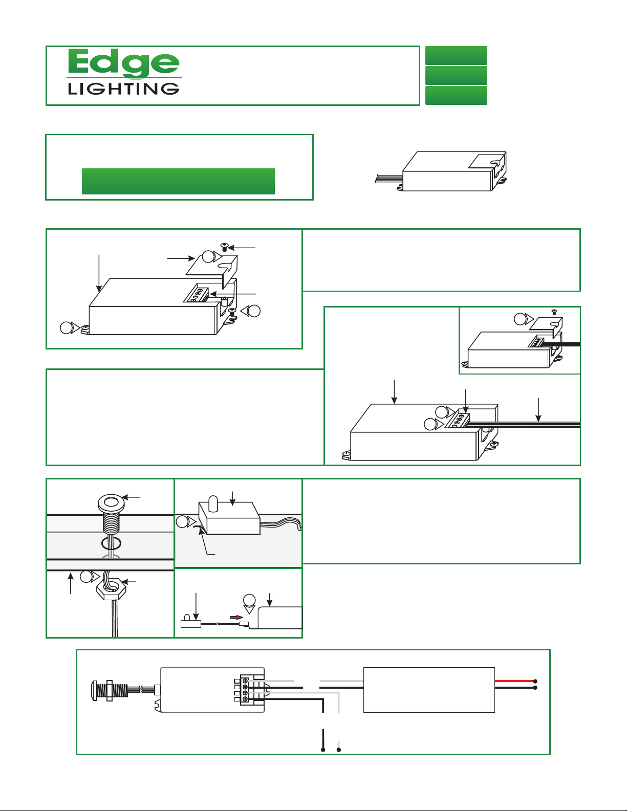
Install the Sensor Switch
904-SEN-IR-01
A
SENSOR SWITCH BOX
2
COVER
1
PHILLIPS
SCREW
WIRE
TERMINAL
BLOCK
2
3: Refer to the wiring diagram below, connect the hot & neutral
power line to the L & N input 120 terminals.
4: Connect the hot & neutral power supply wires to the L & N
output terminal.
5: Replace the sensor switch box cover and secure it by
tightening the Phillips screw.
C
SENSOR
7
SENSOR
1: Loosen the Phillips screws on top of the sensor switch box to
remove the cover exposing the terminal blocks.
2: Secure the sensor switch box to the desired location with
the two screws.
B
SENSOR SWITCH BOX
TERMINAL BLOCK
4
3
5
120VAC POWER
WIRES
6: Install sensor within 3 feet of the sensor switch.
Test Prior installation.
7: Depending on model use either double sided tape or make a
7/16" hole to secure the sensor in place.
DOUBLE
SIDED TAPE
7
PANEL
SENSOR
KNURLED
NUT
WITHIN
3FEET
SENSOR
SENSOR SWITCH
OUTPUT
120-240VAC
INPUT
120-240VAC
General Wiring Diagram
SENSOR
SWITCH BOX
8
NN
L
L
8: Connect the sensor wires to the sensor box.
POWER SUPPLY
NEUTRAL
LINE
NEUTRAL
LINE
INPUT
120VAC
OUTPUT
24VDC
1
 Loading...