

Page 1
© 2013 Edge Lighting. All Rights Reserved.
1718 W. Fullerton Ave
Chicago, IL 60614
Tel: 773-770-1195
Fax: 773-935-5613
www.edgelighting.com
info@edgelighting.com
AD-7WDC-FTP-__
KD-7WDC-FTP-__
904-KAD-FTP-02
Installation Instructions for
Angle and Kurve Display Sign w/Feed
Through-Power
IMPORTANT INFORMATION
- This instruction shows a typical installation.
SAVE THESE INSTRUCTIONS!
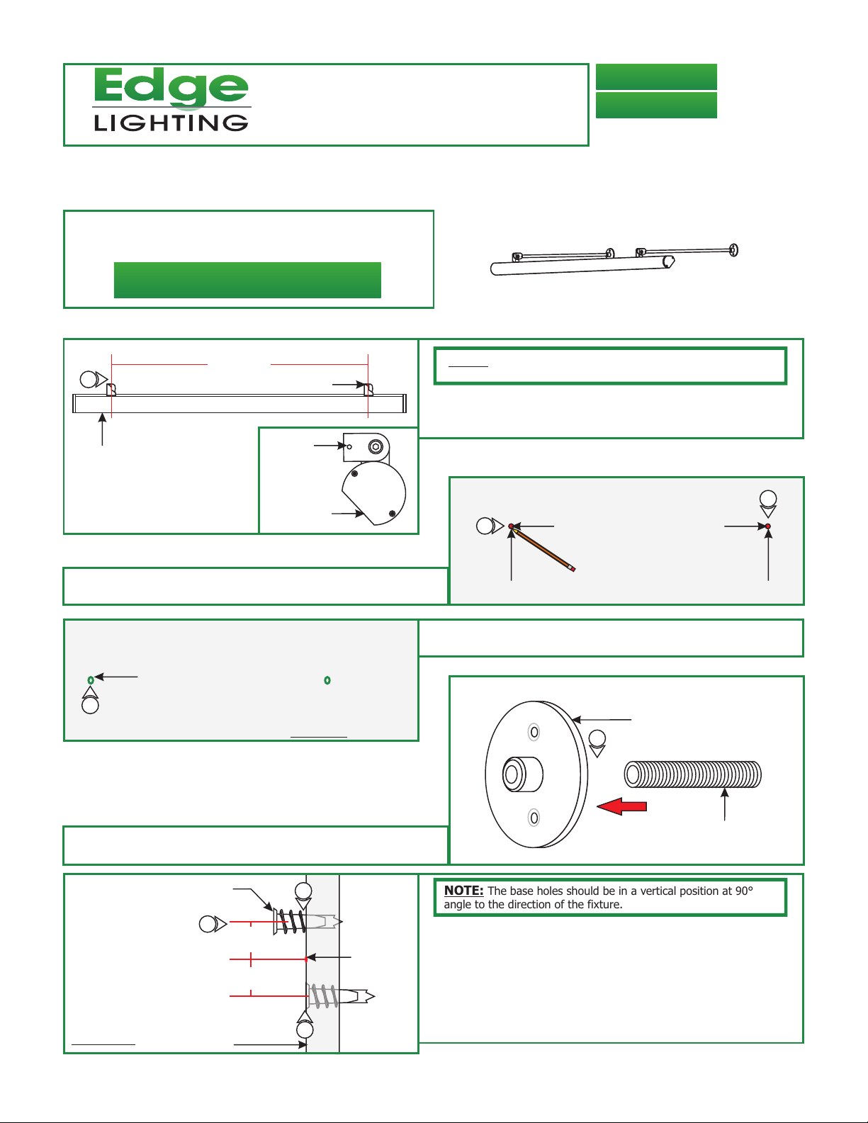
Install the Fixture
A
1
CHANNEL
MEASURE
HINGE
HINGE
NOTE: Depending on fixture length, the fixture is provided with 2
to 4 hinges.
: Measure the distance from center of each hinge to the other
1
hinge. Typically, the furthest left hinge contains the power
wires.
B
CHANNEL
2: Mark the measured points on the wall where the fixture is to
be mounted.
2
MARK
MEASUREMENTS FROM STEP 1
2
MARK
C
POWER
FEED HOLE
3
DRYWALL
4: Insert and tighten the nipple into the back of the stem base
with threads, for the power feed.
E
SIDE VIEW
ANCHOR FOR
STANDOFF POST
5
WALL
0.6"
APART
0.6"
APART
6
MARKED
POINT
7
3: Using a 7/16" bit, drill out the left marked hole through the
front & back drywall surfaces.
D
THREADED
STEM BASE
4
NIPPLE
NOTE: The base holes should be in a vertical position at 90°
angle to the direction of the fixture.
5:
Mark additional points at 0.6" to the top & bottom of the
drilled and marked points.
6:
Use a hammer to tap in the anchors on the (new) marked
points up to the threaded portion.
7: Screw in the threaded portion of the anchors with a Phillips
screwdriver.
1
Page 2
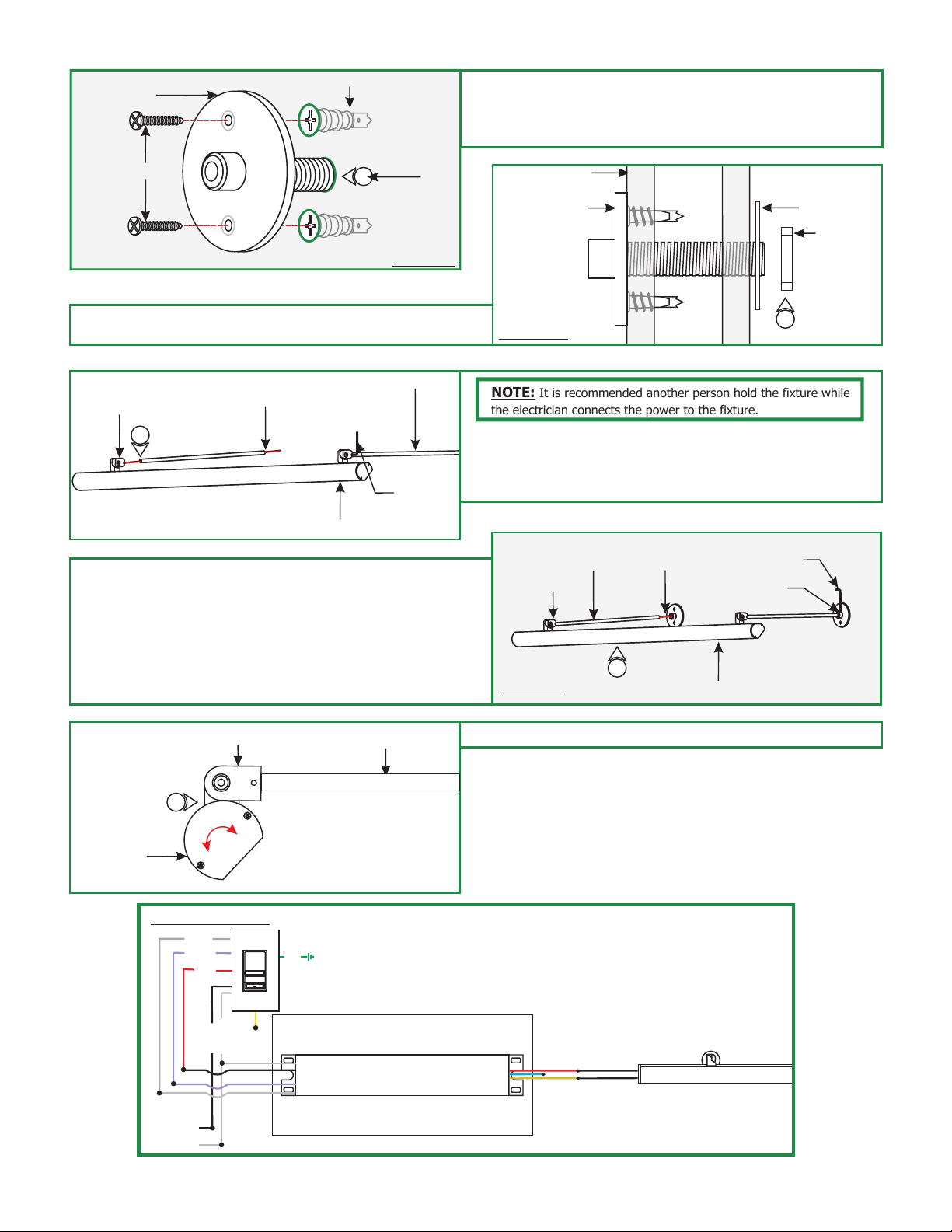
F
BASE
ANCHOR
8: Insert the base nipple into the hole and secure using
the two #8 screws provided.
9: Repeat step 8 for the other bases (without the nipple).
#8 SCREW
8
NIPPLE
DRYWALL
10: Power Feed Base Only: secure from behind the wall
using the large washer and nut.
H
HINGE
POWER
WIRES
11
FIXTURE BODY
STEM
1.5MM ALLEN
WRENCH
12: While feeding the power wires into the base, slide the
stems into the bases. Secure the stems in place by
ightening the M4 set screw on the bases with 2MM Allen
t
wrench.
G
WALL
POWER
WASHER
FEED BASE
NUT
10
SIDE VIEW
NOTE: It is recommended another person hold the fixture while
the electrician connects the power to the fixture.
11: Feed the stem into the fixture hinges and secure by
tightening the M3 set screw with the 1.5MM Allen wrench.
For the power feed hinge carefully run the power
wires through the stem.
I
HINGE
STEM
POWER
WIRES
2MM ALLEN
WRENCH
M4 SET
SCREW
13: Make all the proper wire connections. Refer to the power
supply instructions for additional information.
(General wiring diagram below).
J
14
FIXTURE
HEAD
GENERAL WIRING
GRAY (1-10V)
PURPLE (1-10V)
RED 120VAC
(HOT)
HINGE
WHITE (NEUTRAL)
BLACK (HOT)
GROUND
LIGHTOLIER:
ZP600FAM120
CONTROLLER
POWER SUPPLY (1)
input 120VAC
WH (N)
BK (L)
input 0-10V
PUR
GRY
STEM
PSB-96-010-24VDC
12
DRYWALL
FIXTURE BODY
14: Rotate the fixture head to properly luminate the sign.
RED (24VDC+)
BLUE (RETURN-)
YELLOW (DIM RETURN-)
24VDC
ANGLE/KURVE DISPLAY SIGN
INPUT
120VAC
2
 Loading...