

© 2009 Edge Lighting. All Rights Reserved.
1718 W. Fullerton Ave
Chicago, IL 60614
Tel: 773-770-1195
Fax: 773-935-5613
www.edgelighting.com
info@edgelighting.com
M-HAR-5-GO-_
M2-HAR-5-GO-_
FJ-HAR-5-GO-_
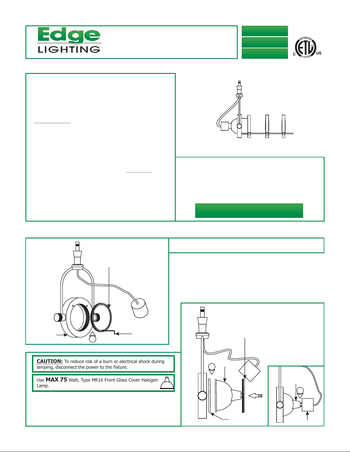
Installation Instructions for Harley with Gobo Holder
IMPORTANT SAFETY INSTRUCTIONS
To reduce the risk of fire, electrical shock, exposure to
excessive UV radiation, or injury to persons:
- Use this fixture indoors only.
- Do not look directly at the lamp while the fixture is on.
- RISK OF FIRE: Use only the type of lamp and maximum
wattage indicated in this instruction manual.
- Never cover the halogen lamp with anything other than a
lamp shield provided by Edge Lighting and never place
flammable material close to the fixture.
- Never turn the fixture on and off by connecting and
disconnecting the halogen lamp.
- Do not touch the fixture head, shade or lamp shield while
the fixture is on. These surfaces may be VERY HOT.
- Do not touch lamp at anytime. Use a soft cloth. Oil from skin
may damage lamp.
- It is normal for a new halogen lamp to produce minor
smoke when first turned on.
- Do not operate the luminaire with a missing or damaged
shield.
- Turn power off and allow to cool before replacing lamp.
IMPORTANT INFORMATION
- This product is ETL listed for indoor dry locations.
- This product is not restricted to certain height installation.
It is approved to be used at any height above the floor.
- Applicable accessories are Hexcell Louver, Glass Lenses,
Gobo, and lens holder.
SAVE THESE INSTRUCTIONS!
904-HAR-5-GO-01
Install the Fixture
A
LENS HOLDER RING
LAMP HOLDER
CAUTION: To reduce risk of a burn or electrical shock during
lamping, disconnect the power to the fixture.
Use MAX 75 Watt, Type MR16 Front Glass Cover Halogen
Lamp.
2: Place an optional optical accessary and lamp into the lamp
holder, and secure them by tightening the lens holder ring to
the lamp holder.
3: Push the socket completely onto the lamp pins.
1
ALLEN WRENCH
1:
Use a small Allen wrench or a pen point to loosen and
remove the lens holder ring from the lamp holder.
B
LENS HOLDER RING
LAMP
2
OPTICAL
ACCESSORY
LAMP
3
SOCKET
1
C
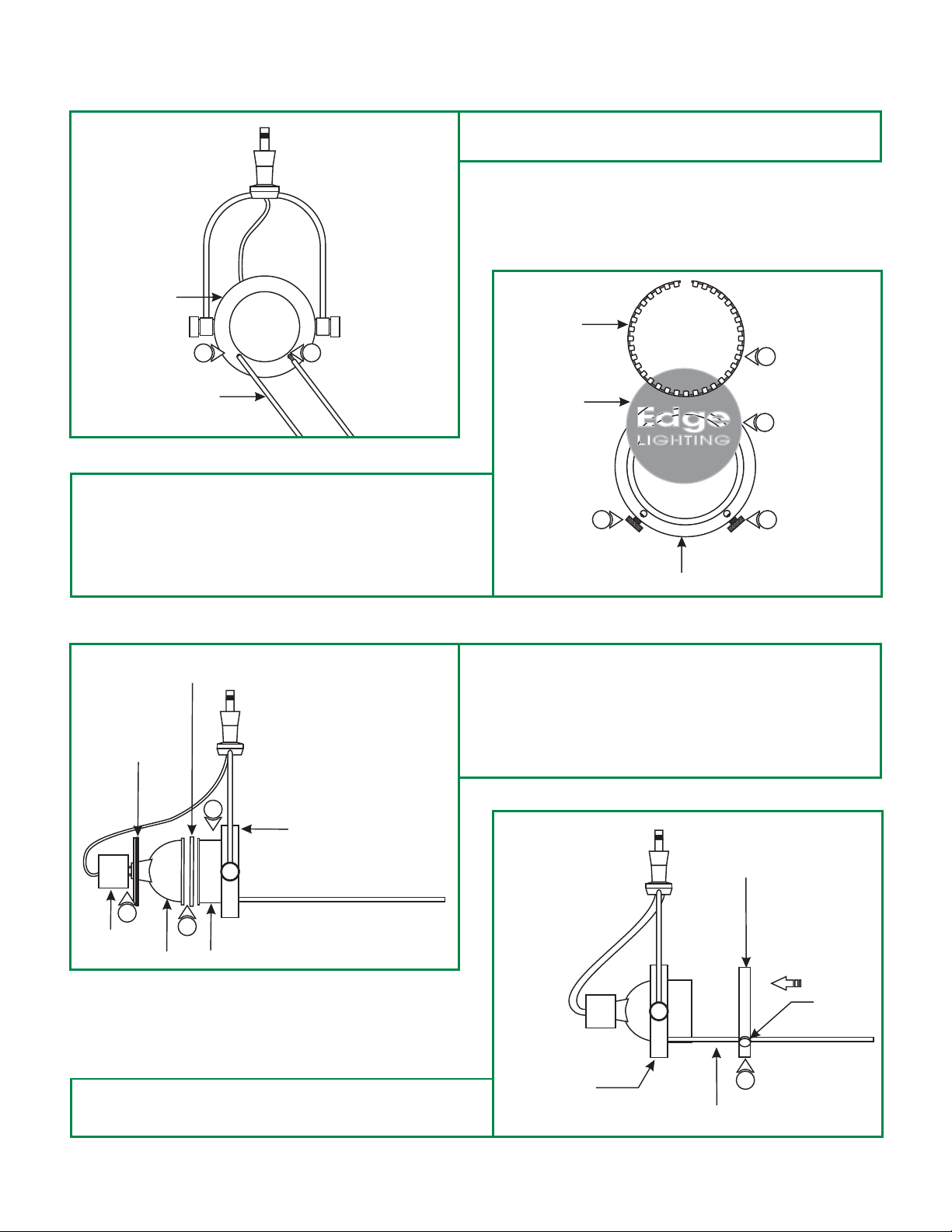
4: Screw the two metal rods completely into the threaded holes
on the lamp holder of the Harley fixture.
LAMP HOLDER
4
METAL ROD
5: Place the gobo inside the gobo holder ring.
6: Squeeze the spring end and place it properly on front of the
gobo into the gobo holder ring.
7: Release the spring ends to secure the gobo in place.
E
LENS HOLDER RING
ACCESSORY
4
D
SPRING
6
GOBO
5
7
GOBO HOLDER RING
8: Place the snoot completely into the lamp holder.
9: Place the lens accessory (optional) in to lamp holder. Place
the lamp completely against the snoot (or lens) and secure
it in place by tightening the ring holder.
10: Push the socket holes completely onto the lamp pins.
7
8
LAMP HOLDER
10
SOCKET
11: Place the gobo holder ring holes onto the metal rods. Slide
the gobo holder ring back against the snoot and tighten the
thumb screws.
LAMP
9
SNOOT
F
LAMP HOLDER
GOBO HOLDER RING
THUMB
SCREW
11
METAL ROD
2

G
MAGNIFYING LENS
HOLDER RING
13
METAL ROD
THUMB
SCREW
15
The projected gobo image on the wall gets larger and the
NOTE:
intensity of the image gets dimmer as the fixture is installed
farther from the wall.
12: Install the harley with the gobo to the corresponding
system by referring to drawing H through K on page 3
and 4.
13: First use the magnifying lens holder with the metal trim.
Place the magnifying lens holder holes onto the metal rods
by sliding the magnifying lens holder. When focused image
is achieved, tighten the thumb screws.
14: If necessary add the second magnifying lens holder ring
(without metal trim-included) to increase the magnified
image size.
15: To increase the image size even bigger, add the third
magnifying lens (optional-sold separately).
Install the Fixture to Monorail
Connector (MC-FJ-_)
1: Place the Fast Jack housing onto the Monorail and use
fingers to tighten the Fast Jack housing connector to the Fast
Jack housing. Make sure that the Fast Jack housing
connector is not cross threaded.
2: Use fingers to tighten the Fast Jack fixture connector into the
Fast Jack housing connector.
FAST JACK
I
HOUSING
1
FAST JACK HOUSING
CONNECTOR
MONORAIL 2 CIRCUIT
2
FAST JACK
FIXTURE
CONNECTOR
2
FAST JACK
H
HOUSING
1
FAST JACK HOUSING
CONNECTOR
2
MONORAIL
2
FAST JACK
FIXTURE
CONNECTOR
Install the Fixture to Monorail
2 Circuit Connector (M2C-FJ-_)
1: Place the Fast Jack housing onto the Monorail 2 Circuit and
use fingers to tighten the Fast Jack housing connector to the
Fast Jack housing. Make sure that the Fast Jack housing
connector is not cross threaded.
2: Use fingers to tighten the Fast Jack fixture connector into
the Fast Jack housing connector.
3

CIRCUIT #1 CIRCUIT #2
J
0.05 ALLEN
WRENCH
3
#4-40 SET
SCREW
1
2
N
3: To power the fixture from circuit #1, top and bottom
(neutral) rails, tighten the #4-40 set screw on top of the
housing with the 0.05 Allen wrench. Make sure this set
screw connection is very tight.
4: To power the fixture from circuit #2, middle and bottom
(neutral) rails, remove the #4-40 set screw from top of the
4
housing and tighten it into the side threaded hole with the
0.05 Allen wrench. Make sure this set screw connection
1
is very tight.
2
N
To avoid shorting the system, do not use more than one
NOTE:
set screw to select a circuit on the Monorail 2 Circuit connector.
NOTE: Do not load either circuit over the maximum system
rating.
Install the Fixture to Fast Jack
Canopy (FJP-2SQ-_, FJP-4SQ-_,
FJP-4RD-_)
1: Use fingers to tighten the Fast Jack fixture connector into
the Fast Jack canopy connector.
K
FAST JACK FIXTURE
CONNECTOR
FAST JACK CANOPY
1
CONNECTOR
1
4
 Loading...