

Edge Lighting Greta LED User Manual
1718 W. Fullerton Ave
Chicago, IL 60614
Tel: 773-770-1195
Fax: 773-935-5613
www.edgelighting.com
© 2014 Edge Lighting. All Rights Reserved.
info@edgelighting.com
Installation Instructions for Greta LED
IMPORTANT INFORMATION
- Use this fixture indoors only.
- This product is ETL listed for indoor dry locations.
- This product is wall mounted only.
- This product can mount to either a 4" square junction box
with round plaster ring or an octagon junction box.
- This product can be dimmed with a standard low-voltage
electronic dimmer.
- This product must be installed by a qualified electrician.
- Before beginning any electrical work, ensure that
power to the junction box is turned OFF.
SAVE THESE INSTRUCTIONS!
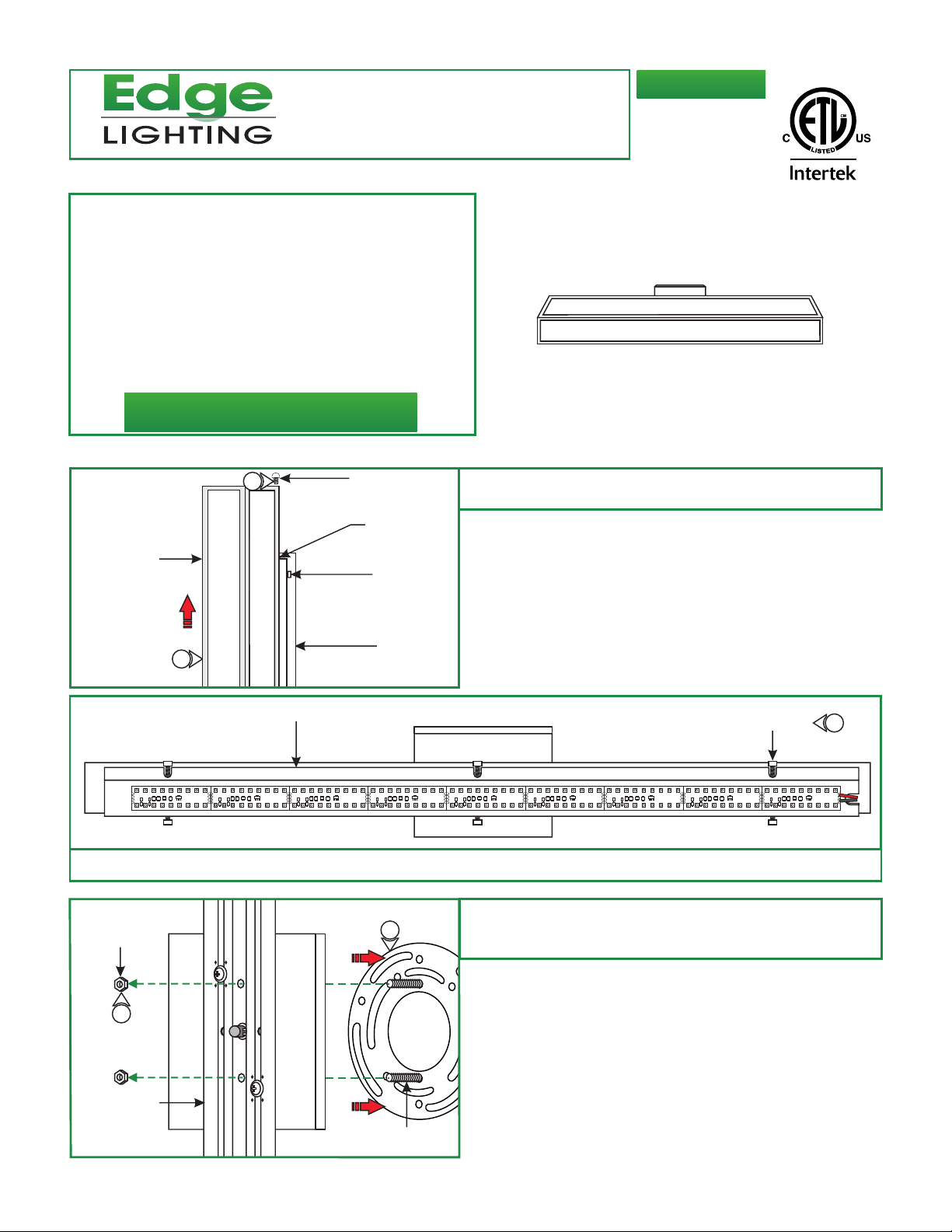
Disassemble the Fixture
A
1
PHILLIPS SCREW
SLOT
GRETA-W-_-L1-_
M2-IND-_
1: Remove the Phillips screw on one end of the shade and slide
the shade off the backplate.
904-GRETA-W-L1-04
SHADE
1
B
2: Remove the LED mounting plate by loosening the six 1.5mm screws using an M3 Allen wrench.
LED MOUNTING
PLATE
C
NUT
SCREW HEAD
BACKPLATE
3: Loosen and remove two nuts from the threaded posts
4
4: Remove the fixture back plate from the mounting plate.
1.5MM SCREW
2
3
BACK PLATE
MOUNTING
POST
1

Install the Fixture
D
2
JUNCTION BOX
1
WIRE NUT
LED TRANSFORMER
1: Connect the white LED transformer wire to the neutral
power wire with a wire nut.
2: Connect the black LED transformer wire to the hot power
wire with a wire nut.
3: Place the LED transformer and all wire connections inside
the junction box.
E
JUNCTION
BOX HOLE
Feed the LED power wires through the mounting plate center
4:
cutout.
5: Place the mounting plate to the junction box and level
mounting studs.
6: Secure the mounting plate to the junction box using two
#8-32 screws.
F
NUT
8
BACK PLATE
7
MOUNTING
POST
MOUNTING
PLATE
#8-32 SCREW
NOTE: It is recommended more than one person assist with
installing this fixture.
Feed the LED transformer power wires through the strain
7:
relief center hole of the backplate and canopy.
8: Place the back plate and canopy on to the mounting posts
and tighten both nuts securely.
4
5
6
G
9: Align the backplate screw holes to the electrical box
mounting holes, and place the backplate on wall to mark
the anchor location.
10a: If mounting fixture centered: mark the end holes on
the wall. These marked holes are for anchors.
10b: If mounting fixture off centered: slightly loosen the
two backplate screws and slide the backplate to the
desired position and tighten the backplate screws. Mark
the end holes of the backplate on the wall. These marked
holes are for anchors.
END
HOLE
10a
ADJUSTMENT
BACKPLATE
SCREW
10b
MOUNTING
PLATE
BACKPLATE
2
 Loading...