

Edge Lighting Grazie User Manual
1718 W. Fullerton Ave
Chicago, IL 60614
Tel: 773-770-1195
Fax: 773-935-5613
www.edgelighting.com
© 2014 Edge Lighting. All Rights Reserved.
info@edgelighting.com
Installation Instructions for Grazie Suspension
IMPORTANT SAFETY INSTRUCTIONS
To reduce the risk of fire, electrical shock, exposure to
excessive UV radiation, or injury to persons:
- Turn power to junction box OFF before beginning any
electrical work.
- Do not look directly at the lamp while the fixture is on.
- RISK OF FIRE: Use only the type of lamp and maximum
wattage indicated in this instruction manual.
- Never turn the fixture on and off by connecting and
disconnecting the halogen lamp.
- Do not touch the fixture head, shade or lamp shield while
the fixture is on. These surfaces may be VERY HOT.
IMPORTANT INFORMATION
- This product is suitable for indoor locations.
- This product can mount to either a 4" square electrical box
with round plaster ring or an octagon electrical box.
- This product is dimmable with a standard incandescent
dimmer.
GRAZIE-S-__-__
904-GRAZIE-01
SAVE THESE INSTRUCTIONS!
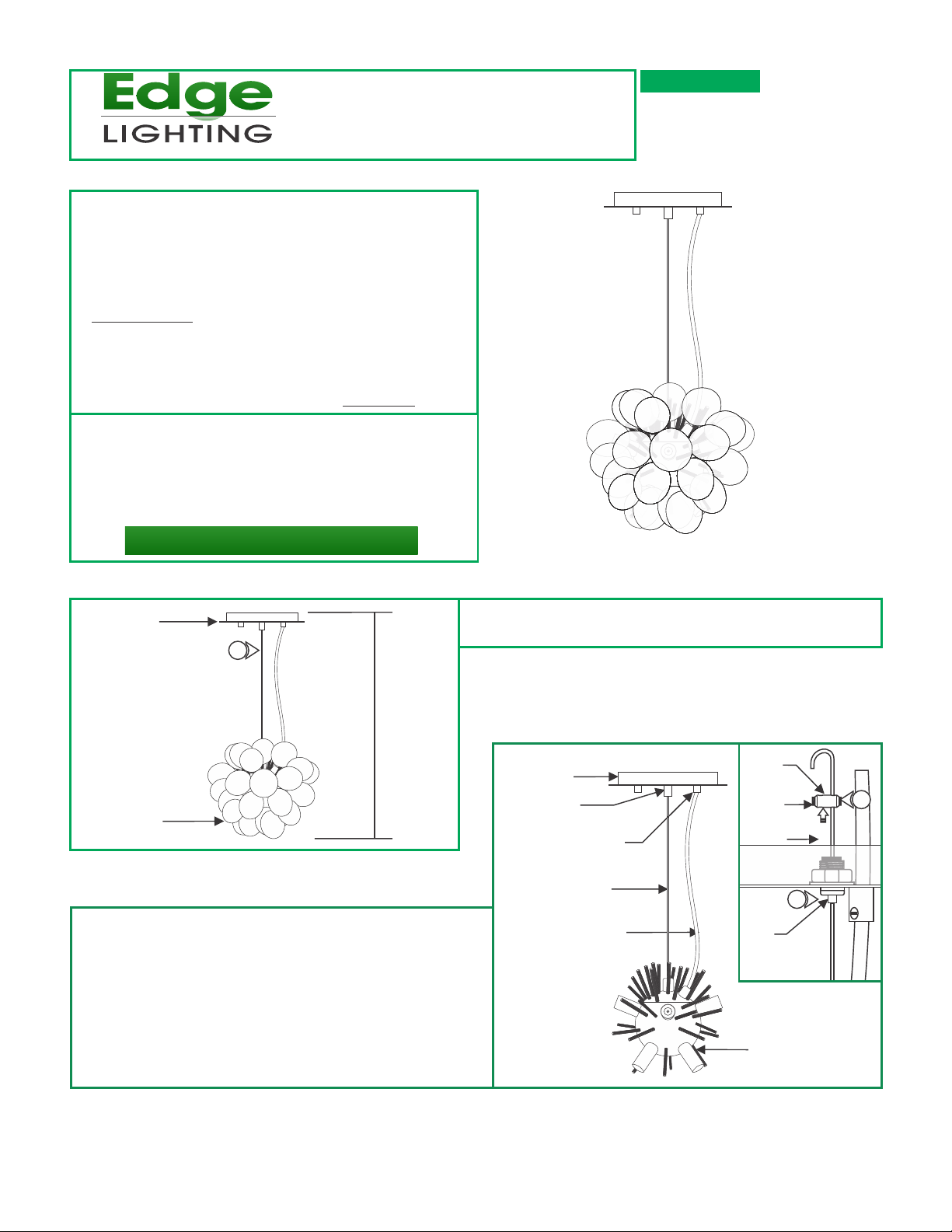
Install Fixture
A
CANOPY
1
H
GLASS
ORNAMENT
2: Slide the canopy up and down by pushing the tab on the
aircraft cable grip until desired height is achieved. Release
the tab to lock the aircraft cable in place.
3: Loosen the M4 set screws on both sides of the strain
relief with the 2mm Allen wrench.
1: Determine the desired fixture height (H), from the bottom of
the glass ornaments to the top of the canopy.
B
CANOPY
CABLE GRIP
CORD GRIP
AIRCRAFT CABLE
CLEAR CORD
STRAIN
RELIEF
SET
SCREW
AIRCRAFT
CABLE
CABLE
GRIP
3
2
4: Pull the end of the aircraft cable out of one strain relief hole.
Slide the strain relief down the aircraft cable behind the cable
grip.
SOCKET HOUSING
1
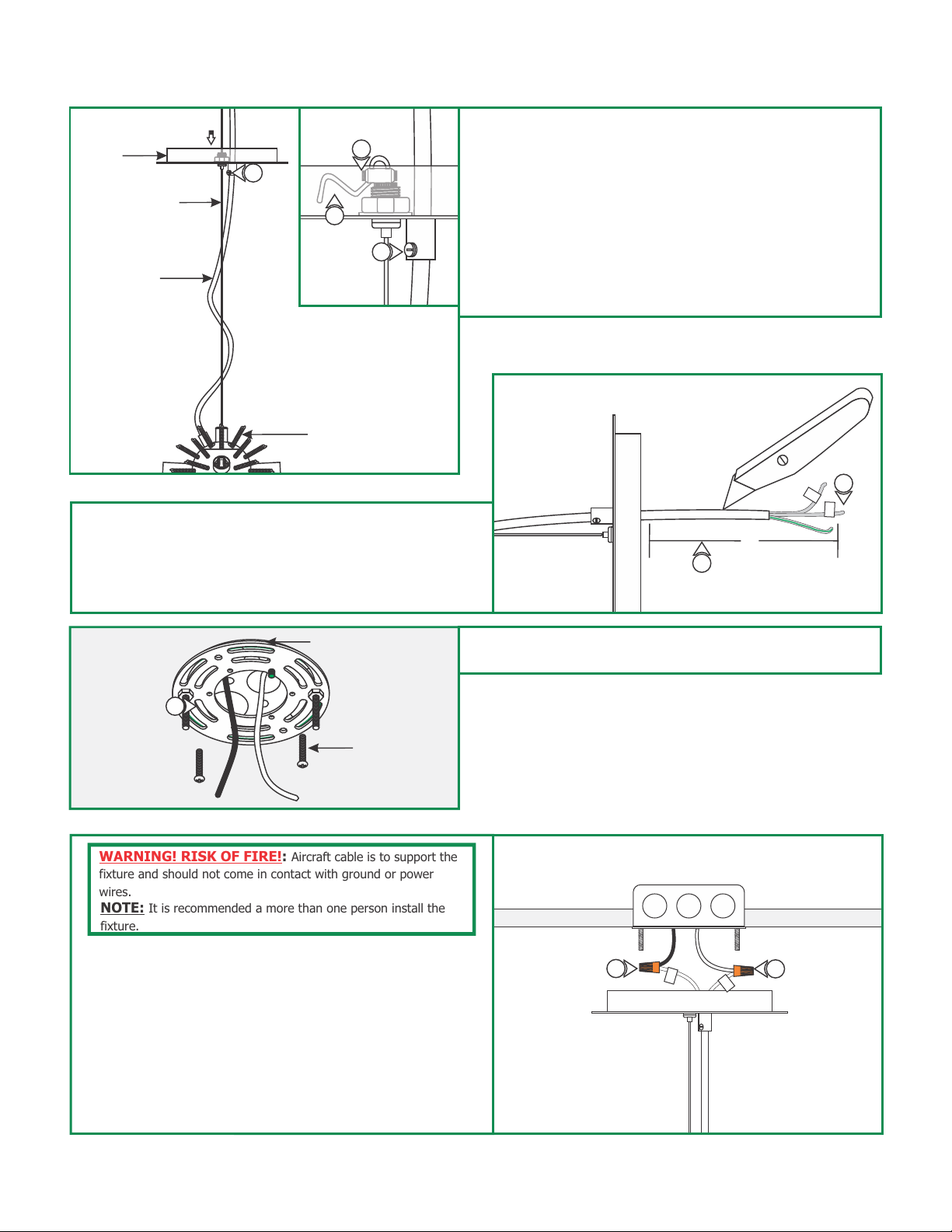
C
CANOPY
8
AIRCRAFT CABLE
CLEAR CORD
SOCKET HOUSING
9: Leave 8" of the clear cord exposed behind the canopy for
power connection. Trim off the excess clear cord.
10: From the end of the clear cord, strip 4" of the outer
insulation using a sharp knife. Make sure not to nick the
inner wires. Trim off the cut out insulation.
5
6
7
5: Loop the end of the aircraft cable into the other strain relief
hole and tighten the two M4 set screws with the 2mm Allen
wrench.
6: Trim off excess aircraft cable behind the strain reliefs with a
sharp cutter.
7: Loosen the slotted set screw on the cord grip with a flat
screwdriver and push the excess clear cord into the canopy.
8: Tighten the slotted set screw on the cord grip to lock the
clear cord in place.
D
10
L
N
8"
9
E
11
WARNING! RISK OF FIRE!: Aircraft cable is to support the
fixture and should not come in contact with ground or power
wires.
NOTE: It is recommended a more than one person install the
fixture.
12: Turn power to junction box OFF before beginning any
electrical work.
13: Make sure that the canopy is grounded in accordance with
local electrical codes.
14: Connect the wire labeled "N" to the neutral power wire
with a wire nut.
CROSSBAR ASSEMBLY
#8-32 SCREW
11: Mount the crossbar assembly to the electrical box holes
with the two #8-32 screws provided.
F
15
L
14
N
15: Connect the wire labeled "L" to the hot power wire with a
wire nut.
2
 Loading...