

Page 1
1718 W. Fullerton Ave
Chicago, IL 60614
Tel: 773-770-1195
Fax: 773-935-5613
www.edgelighting.com
© 2010 Edge Lighting. All Rights Reserved.
info@edgelighting.com
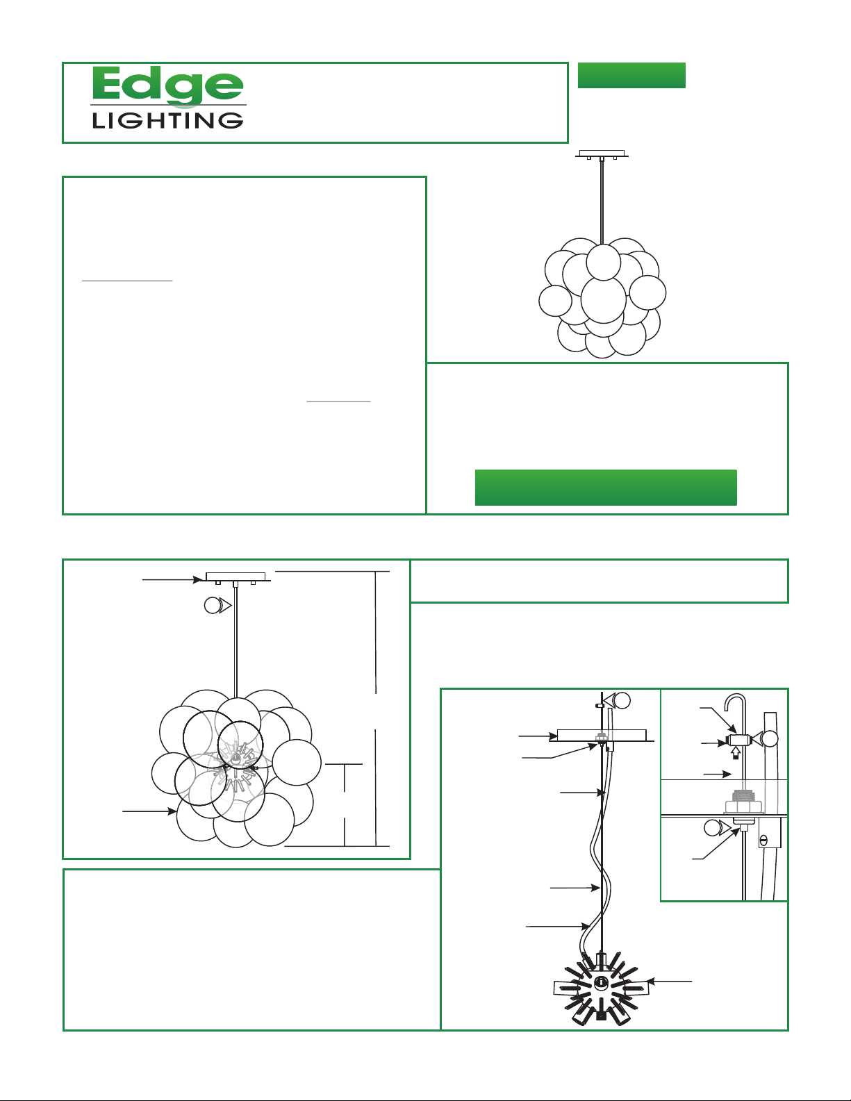
Installation Instructions for Graciano Suspension
IMPORTANT SAFETY INSTRUCTIONS
To reduce the risk of fire, electrical shock, exposure to
excessive UV radiation, or injury to persons:
- Do not look directly at the lamp while the fixture is on.
- RISK OF FIRE: Use only the type of lamp and maximum
wattage indicated in this instruction manual.
- Never cover the halogen lamp with anything other than a
lamp shield provided by Edge Lighting and never place
flammable material close to the fixture.
- Never turn the fixture on and off by connecting and
disconnecting the halogen lamp.
- Do not touch the fixture head, shade or lamp shield while
the fixture is on. These surfaces may be VERY HOT.
- Do not touch lamp at anytime. Use a soft cloth instead as oil
from skin may damage lamp.
- It is normal for a new halogen lamp to produce minor
smoke when first turned on.
- Do not operate the luminaire with a missing or damaged
shield.
- Turn power off and allow to cool before replacing lamp.
IMPORTANT INFORMATION
- This product is suitable for indoor locations.
- This product can mount to either a 4" square electrical box
with round plaster ring or an octagon electrical box.
- This product is dimmable with a standard incandescent
dimmer.
SAVE THESE INSTRUCTIONS!
GRACIANO-S-_
904-GRACIANO-02
Install the fixture
A
CANOPY
1
H
GLASS
ORNAMENT
2: Slide the canopy up and down by pushing the tab on the
aircraft cable grip until desired height is achieved. Release
the tab to lock the aircraft cable in place.
3:
Loosen the M4 set screws on both sides of the strain
relief with the 2mm Allen wrench.
4:
Pull the end of the aircraft cable out of one strain relief hole.
Slide the strain relief down the aircraft cable behind the cable
grip.
12"
1: Determine the desired fixture height (H), from the bottom of
the glass ornaments to the top of the canopy.
B
CANOPY
CABLE GRIP
AIRCRAFT CABLE
CLEAR CORD
4
CORD GRIP
STRAIN
RELIEF
SET
SCREW
AIRCRAFT
CABLE
2
CABLE
GRIP
SOCKET HOUSING
3
1
Page 2
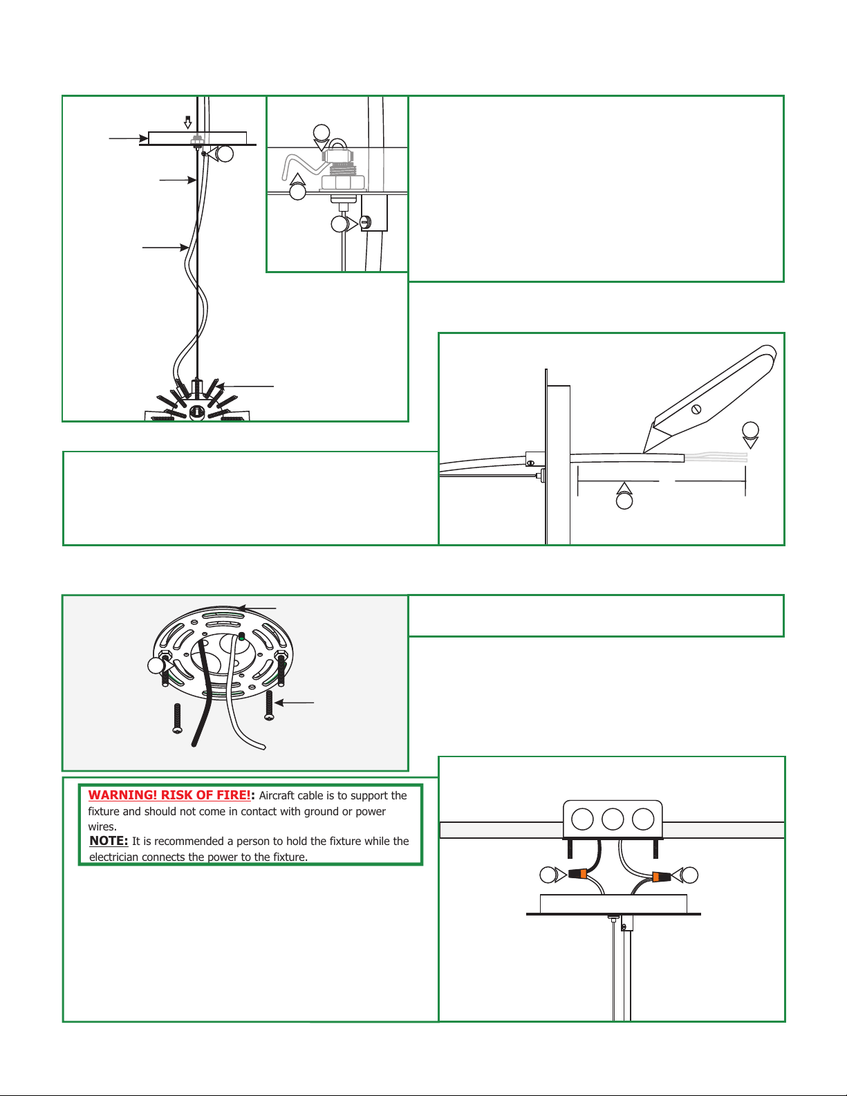
C
CANOPY
8
AIRCRAFT CABLE
CLEAR CORD
SOCKET HOUSING
9: Leave 8" of the clear cord exposed behind the canopy for
power connection. Trim off the excess clear cord.
10: From the end of the clear cord, strip 4" of the outer
insulation using a sharp knife. Make sure not to nick the
inner wires. Trim off the cut out insulation.
5
6
7
5: Loop the end of the aircraft cable into the other strain relief
hole and tighten the two M4 set screws with the 2mm Allen
wrench.
6: Trim off excess aircraft cable behind the strain reliefs with a
sharp cutter.
7: Loosen the slotted set screw on the cord grip with a flat
screwdriver and push the excess clear cord into the canopy.
8: Tighten the slotted set screw on the cord grip to lock the
clear cord in place.
D
10
8"
9
E
11
WARNING! RISK OF FIRE!: Aircraft cable is to support the
fixture and should not come in contact with ground or power
wires.
NOTE: It is recommended a person to hold the fixture while the
electrician connects the power to the fixture.
12: Make sure the power to the electrical box is off.
13: Make sure that the canopy is grounded in accordance with
local electrical codes.
14: Connect the clear wire with a rough edge to the neutral
power wire with a wire nut.
15: Connect the other clear wire to the hot power wire with a
wire nut.
CROSSBAR ASSEMBLY
#8-32 SCREW
11: Mount the crossbar assembly to the electrical box holes
with the two #8-32 screws provided.
F
15
14
2
Page 3

G
CANOPY
17
16
THREADED
STUD
16: Place all wires and wire nut connections inside the canopy.
17: Align and slide the canopy holes onto the threaded studs.
While holding the canopy, tighten the two thumb nuts to
secure the canopy in place.
THUMB NUTS
CAUTION: To reduce risk of a burn or electrical shock during
lamping, disconnect the power to the fixture.
NOTE: The G9 lamp has an integral glass envelope and is thus
safe to be used without a lamp shield.
NOTE: Use only fingers and a soft cloth to install the lamps.
Use MAX 40 Watt Type T4, G9 Base, Bi-Pin
Halogen Lamp, For Each Socket.
:
1 For each socket, push the lamp pins completely into the
socket holes.
I
KEY RING
2
Install the Lamps & Glass
Ornaments
H
SOCKET
LAMP
1
2: Squeeze the key ring to open the ends. Slide one end
2
through a glass ornament.
SOCKET HOUSING
1
GLASS
ORNAMENT
3: Squeeze the key ring to open the ends and slide one end into
a socket housing spring.
4: Repeat steps 2 and 3 for the remaining glass ornaments.
J
SOCKET HOUSING
SPRING
3
KEY RING
4
3
 Loading...