

Page 1
1718 W. Fullerton Ave
Chicago, IL 60614
Tel: 773-770-1195
Fax: 773-935-5613
www.edgelighting.com
© 2010 Edge Lighting. All Rights Reserved.
info@edgelighting.com
Installation Instructions for Frame Halogen Kit
IMPORTANT SAFETY INSTRUCTIONS
To reduce the risk of fire, electrical shock, exposure to
excessive UV radiation, or injury to persons:
- Use this fixture indoors only.
- Do not look directly at the lamp while the fixture is on.
- RISK OF FIRE: Use only the type of lamp and maximum
wattage indicated in this instruction manual.
- Never cover the halogen lamp with anything other than a
lamp shield provided by Edge Lighting and never place
flammable material close to the fixture.
- Never turn the fixture on and off by connecting and
disconnecting the halogen lamp.
- Do not touch the fixture head, shade or lamp shield while
the fixture is on. These surfaces may be VERY HOT.
- Do not touch lamp at anytime. Use a soft cloth instead as oil
from skin may damage lamp.
- It is normal for a new halogen lamp to produce minor
smoke when first turned on.
- Turn power off and allow to cool before replacing lamp.
IMPORTANT INFORMATION
- This product is ETL listed for indoor dry locations.
- This product is wall mounted only.
- This product can be dimmed with an electronic low voltage
dimmer.
SAVE THESE INSTRUCTIONS!
FRAME-KIT-H1-_
904-FRAME-KIT-H1-01
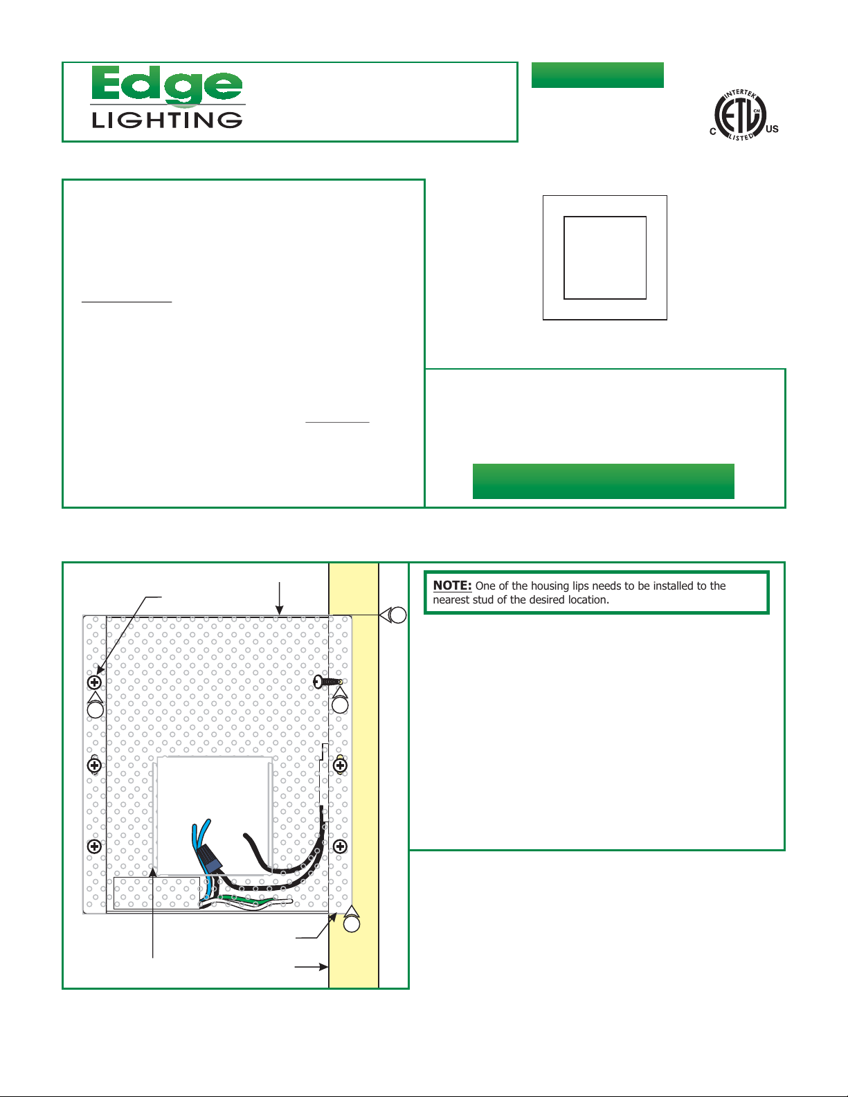
Install the Vision Housing
A
#8 SCREW
5
PLASTER SCREEN
4
3
HOUSING LIP
NOTE: One of the housing lips needs to be installed to the
nearest stud of the desired location.
1
Mark the location on the stud where the housing will be
1:
mounted.
2: Place the plaster screen in front of the housing so that the
folded lips face outside.
3: Line up the screw holes on the plaster screen with the screw
holes of the housing and place one housing lip against the
marked stud.
4: Secure the housing along with the plaster screen to the stud
with the provided three #8 screws.
5: Use the other three #8 screws to secure the plaster screen
to the housing.
FOLDED LIP
STUD
1
Page 2
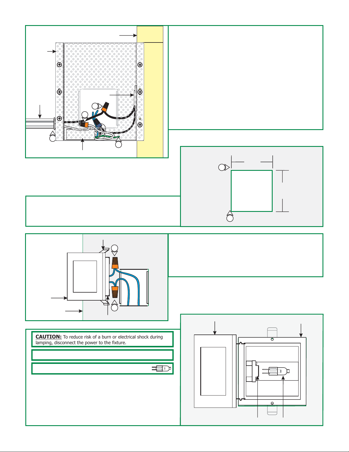
B
HOUSING
CONDUIT
THERMAL
PROTECTOR
10
9
STUD
6: Remove a knock out to install the power line conduit.
7: Install the conduit and run the power line wires to the
housing.
8: Make sure that the housing is grounded in accordance with
local electrical codes.
9: Connect the white transformer wire to the neutral power
line wire with a wire nut.
10: Connect the black thermal protector wire to the hot power
line wire with a wire nut.
11: The black transformer wire is connected by default to the
other wire of the thermal protector.
7
8
TRANSFORMER
1: Mark 3.2" square(s) on drywall where the housing opening is
(are) located.
2: Cut out the marked square(s) and install the drywall.
D
COVER
DRYWALL
SPRING CLIP
3
3
TRIM
Install Drywall, Trim & Lamp
C
1
2
3: After installing drywall and finishing it, connect each wire
coming out of the housing opening to one trim wire with a
wire nut.
4: Place all wires inside the housing and gently push the trim
into the housing opening by squeezing the springs clips.
E
TRIM COVER
3.2"
3.2"
TRIM HOUSING
CAUTION:
lamping, disconnect the power to the fixture.
NOTE: Use only fingers and a soft cloth to install the lamps.
Use MAX 20 Watt Bi-Pin Halogen Lamp.
10: Carefully pull the trim cover out of the housing to expose
the socket.
11: Push the lamp pins completely into the socket assembly
holes.
12: Replace and push the trim cover back into the trim housing
until it snaps into place.
To reduce risk of a burn or electrical shock during
SOCKET
LAMP
2
 Loading...