

Page 1
© 2009 Edge Lighting. All Rights Reserved.
1718 W. Fullerton Ave
Chicago, IL 60614
Tel: 773-770-1195
Fax: 773-935-5613
www.edgelighting.com
info@edgelighting.com
MTFJ-150-12-_
PATENT PENDING
904-MTFJ-150-12-03
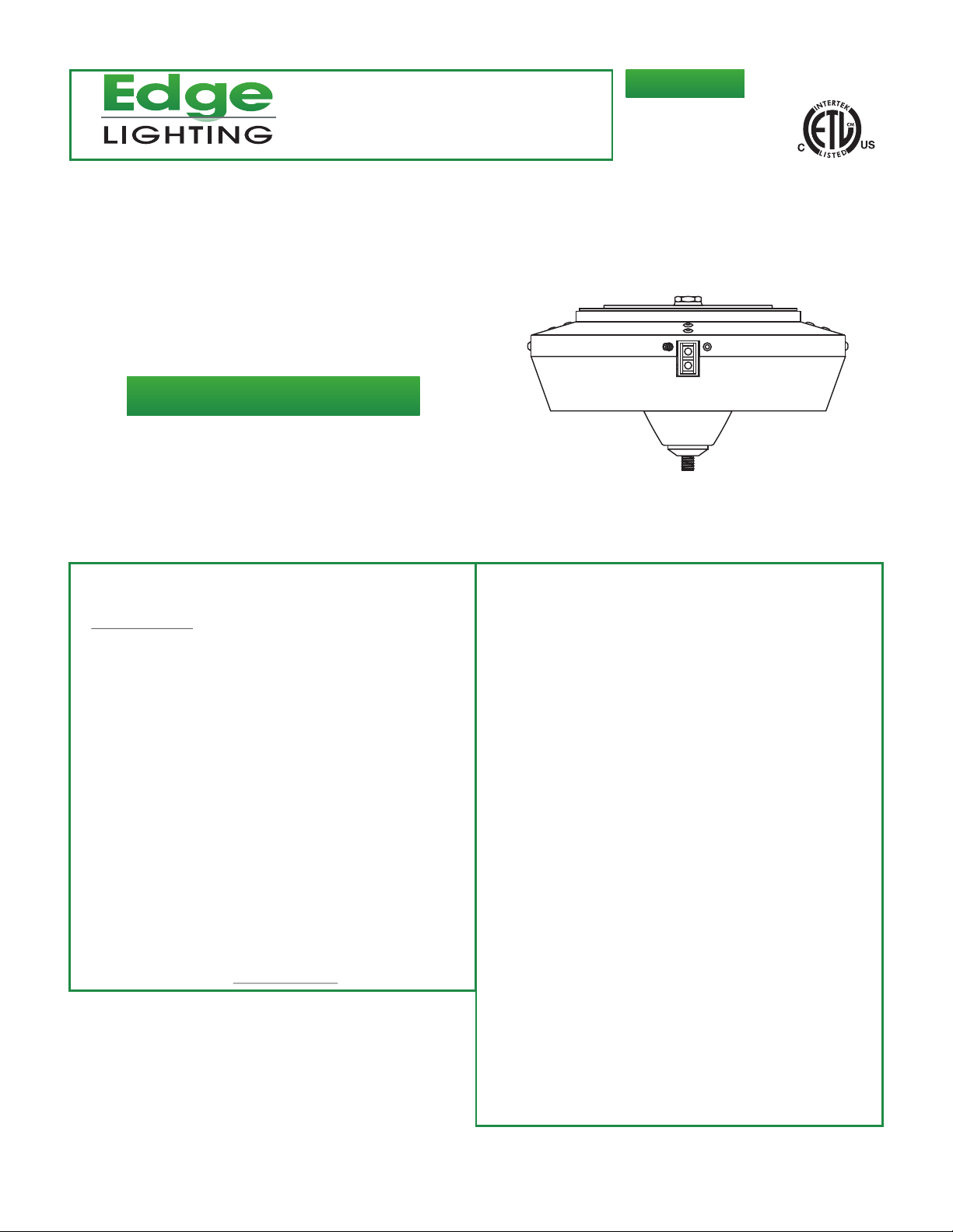
Installation Instructions for Monorail 150
Magnetic Transformer
120 Volt Input to 12 Volt Single Feed
Watt Surface Mount
Output with Fast Jack Port
SAVE THESE INSTRUCTIONS!
GENERAL INFORMATION IMPORTANT SAFETY INSTRUCTIONS
- RISK OF FIRE: This product must be installed by a
qualified electrician. Turn the power to the electrical box off
during installation. Read the "Important Safety Instructions"
before installation.
- This product is suitable only for indoor dry locations and
approved for the use at any height above the finished floor.
- This product contains a magnetic transformer with a built-in
dimming coil.
- Do not install this lighting system in a damp or wet
location.
- Do not conceal or extend bus bar conductor through
building wall.
- To reduce the risk of fire and burns, do not install this
lighting system where the insulated open bus bar
conductors can be shorted or contact any conductive
materials.
- This product may be dimmed only with a low voltage
magnetic dimmer. Using a dimmer other than specified may
work initially, but will eventually cause transformer failure
and void the warranty. The dimmer must be derated as
indicated by the dimmer manufacturer.
- A typical installation is shown. Specific installation must be
in accordance with the local electrical codes.
- Load the circuit of the surface mount transformer along with
the Fast Jack port to a MAXIMUM 150 Watt.
- To reduce the risk of the system overheating and possibly
causing a fire, make sure all the connections are tight.
- Do not install fixture assemblies closer than six inches, or
as specified in the fixture installation instructions, to
curtains or similarly combustible materials.
- Turn the electrical power off before modifying the lighting
system in any way.
- The fixtures used with the Edge Lighting systems must be
identified for use with the corresponding Edge Lighting
systems.
- Minimum volume of the electrical box must be 6 cubic
inches (98 cubic centimeters).
- The system is "ETL" listed for USA and Canada only when
all the products used are supplied by Edge Lighting.
1
Page 2
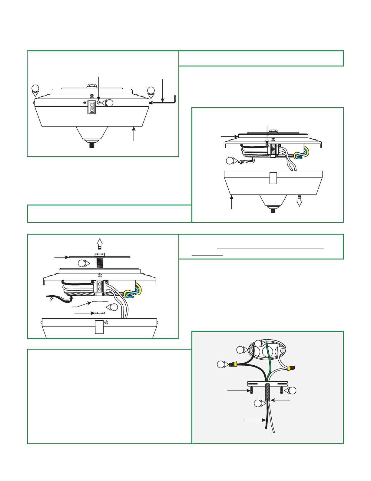
Install the Surface Mount Transformer
A
M4 BUTTON
HEAD SCREW
1
1
COVER
2: While holding the transformer, unhook the transformer cover
from the set screw.
2MM ALLEN
WRENCH
1
1: Loosen and remove the five M4 button head screws around
the transformer cover with the provided 2mm Allen wrench.
B
SET SCREW
HOUSING
2
COVER
C
CROSSBAR
ASSEMBLY
WASHER
INSIDE NUT
4: Connect the provided white and black extension wires to the
neutral and hot power wires respectively with the wire nuts
provided.
5: Feed the wires through the crossbar assembly nipple.
6: Place all wires and wire nut connections inside the electrical
box.
7: Mount the crossbar assembly to the electrical box with the
two provided #8-32 screws.
3
3
3: Remove the inside nut and washer to remove the crossbar
assembly. DO NOT DISASSEMBLE THE CROSSBAR
ASSEMBLY.
D
4
#8-32 SCREW
EXTENSION WIRES
8
6
7
5
CROSSBAR ASSEMBLY
NIPPLE
8: Make sure the crossbar assembly is grounded in accordance
with local electrical codes.
2
Page 3
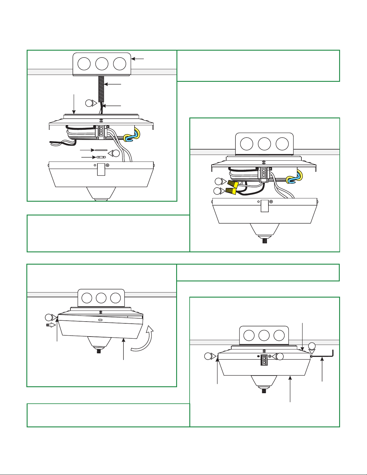
E
HOUSING
ELECTRICAL
BOX
CROSSBAR ASSEMBLY
NIPPLE
9: Feed the extension wires through the transformer housing
center hole. Slide the transformer housing onto the
crossbar assembly nipple and secure it in place by
tightening the washer and inside nut.
9
WASHER
INSIDE NUT
10: Connect the white transformer wire to the neutral power
wire with a wire nut.
11: Connect the black transformer wire to the hot power wire
with a wire nut.
EXTENSION WIRES
9
G
F
10
11
12: Hook one of the transformer cover screw holes next to the
rectangle cutout, onto the Monorail feed contact set screw.
12
MONORAIL FEED
CONTACT SET SCREW
COVER
13: Place the transformer cover onto the transformer housing.
Replace and tighten the five M4 button head screws with
the 2mm Allen wrench.
H
13
M4 BUTTON
HEAD SCREW
HOUSING
13
13
2MM ALLEN
WRENCH
COVER
3
Page 4
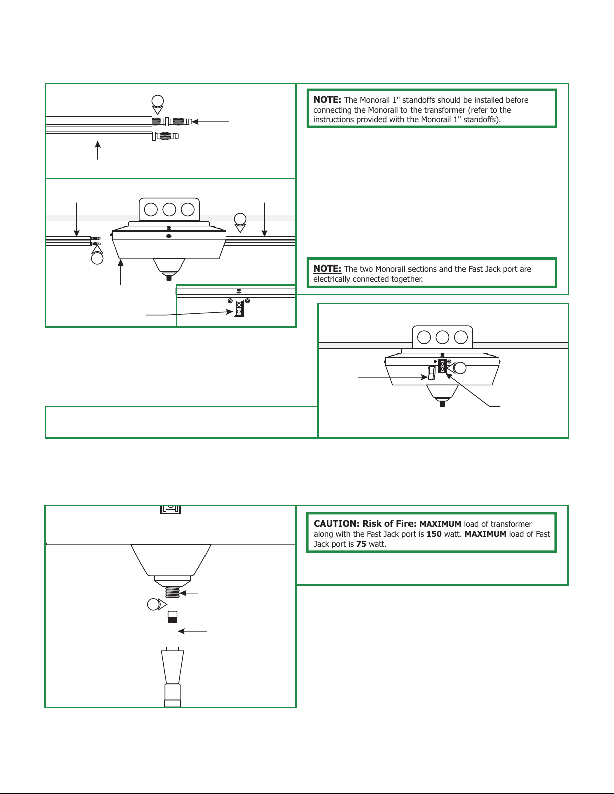
Install the Monorail(s) to the Transformer
I
ONE MONORAIL SECTION
SECOND MONORAIL
SECTION
3
SURFACE TRANSFORMER
MONORAIL FEED CONTACT
The Monorail 1" standoffs should be installed before
1
STRAIGHT
CONDUCTIVE
CONNECTOR
MONORAIL
SECTION
2
NOTE:
connecting the Monorail to the transformer (refer to the
instructions provided with the Monorail 1" standoffs).
1: Push one end of the straight conductive connectors
(provided with the transformer) completely into one end of
the Monorail section.
2: Push the end of the straight conductive connectors (along
with the Monorail) completely into one Monorail feed
contact. While supporting the Monorail section by hand
connect this section to the Monorail 1" standoffs (refer to the
instructions provided with the Monorail 1" standoffs).
3: If using second Monorail section, then repeat steps 1 & 2.
NOTE: The two Monorail sections and the Fast Jack port are
electrically connected together.
J
PLASTIC
INSERT
4
4: Plug the Monorail feed contact with the plastic insert
provided.
Install the Fixture to the Fast Jack Port
K
FAST JACK TRANSFORMER
1
PORT
FAST JACK FIXTURE
CONNECTOR
CAUTION: Risk of Fire: MAXIMUM load of transformer
along with the Fast Jack port is 150 watt. MAXIMUM load of Fast
Jack port is 75 watt.
1:
Use your fingers to tighten the Fast Jack fixture connector
into the Fast Jack transformer port.
MONORAIL FEED
CONTACT
4
 Loading...