

Edge Lighting Everest User Manual
1718 W. Fullerton Ave
Chicago, IL 60614
Tel: 773-770-1195
Fax: 773-935-5613
www.edgelighting.com
© 2011 Edge Lighting. All Rights Reserved.
info@edgelighting.com
Installation Instructions for Everest
IMPORTANT SAFETY INSTRUCTIONS
To reduce the risk of fire, electrical shock, exposure to
excessive UV radiation, or injury to persons:
- Use this fixture indoors only.
- Do not look directly at the lamp while the fixture is on.
- RISK OF FIRE: Use only the type of lamp and maximum
wattage indicated in this instruction manual.
- Never cover the halogen lamp with anything other than a
lamp shield provided by Edge Lighting and never place
flammable material close to the fixture.
- Never turn the fixture on and off by connecting and
disconnecting the halogen lamp.
- Do not touch the fixture head, shade or lamp shield while
the fixture is on. These surfaces may be VERY HOT.
- Do not touch lamp at anytime. Use a soft cloth instead as oil
from skin may damage lamp.
- It is normal for a new halogen lamp to produce minor
smoke when first turned on.
- Do not operate the luminaire with a missing or damaged
shield.
- Turn power off and allow to cool before replacing lamp.
FJ-EVE-_
904-FJ-EVE-01
IMPORTANT INFORMATION
- This product is ETL listed for indoor dry locations and
approved to be used at any height above the finished
floor.
SAVE THESE INSTRUCTIONS!
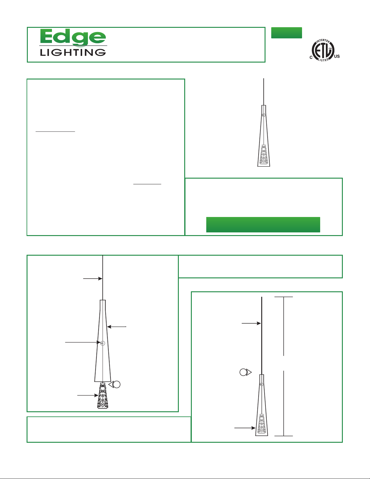
Adjust the Fixture Height
A
COAXIAL CABLE
GLASS SHADE
PLASTIC BALL
STRAIN RELIEF
1
GLASS PENDANT
1: Feed the fixture coaxial cable through the glass shade
respectively and carefully lower the glass shade down to rest
onto the plastic ball strain relief.
B
COAXIAL CABLE
H
2
2: Cut the coaxial cable to the desired height (H) with a sharp
cutter. The overall fixture height is measured from the
bottom of the glass shade to the end of the coaxial cable.
GLASS SHADE
1
1
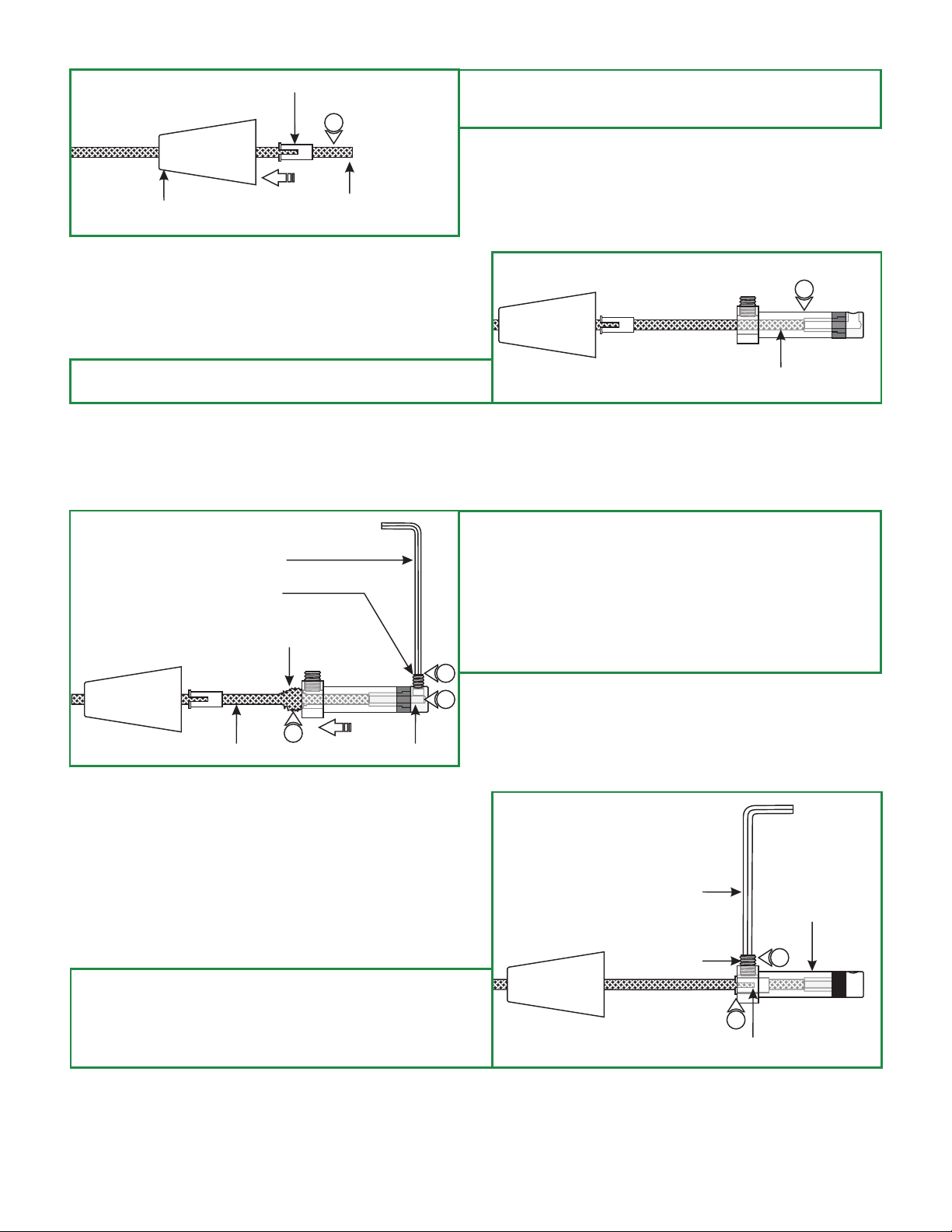
C
STRAIN RELIEF TUBE
3
3: Feed the coaxial cable through the conical nipple and flared
side of the strain relief tube. Slide the conical nipple and
strain relief tube down the coaxial cable.
CONICAL NIPPLE
4: Feed the coaxial cable into the coaxial fixture connector. The
coaxial cable will come to a stop point.
COAXIAL CABLE
E
1.5MM ALLEN WRENCH
M3 SET SCREW
WRINKLE
6
5
D
4
COAXIAL CABLE
5: Keep feeding the coaxial cable in until the inner wire is
visible in the screw hole of the fixture connector tip. The
outer metal jacket will start to wrinkle.
6: Hold the fixture connector in place. Replace and tighten the
M3 set screw on fixture connector tip with the 1.5mm Allen
wrench.
7: Pull down the outer metal jacket to smooth the wrinkles.
7
OUTER METAL JACK INNER WIRE
8: Push the strain relief tube completely into the coaxial
fixture connector. Make sure the slot on the strain relief
tube is not inline with the M4 set screw.
9: Tighten the M4 set screw with the 2mm Allen wrench.
F
2MM ALLEN WRENCH
M4 SET SCREW
COAXIAL FIXTURE
CONNECTOR
9
8
STRAIN RELIEF TUBE
2
 Loading...