

Page 1

© 2009 Edge Lighting. All Rights Reserved.
1718 W. Fullerton Ave
Chicago, IL 60614
Tel: 773-770-1195
Fax: 773-935-5613
www.edgelighting.com
info@edgelighting.com
904-TE-300-12-02
TE-300-12
Installation Instructions for
300 Watt Remote Electronic Transformer
120 Volt Input to 12 Volt Single Feed Output
SAVE THESE INSTRUCTIONS!
GENERAL INFORMATION IMPORTANT SAFETY INSTRUCTIONS
- RISK OF FIRE: This product must be installed by a
qualified electrician. Turn the power to the electrical box off
during installation. Read the "Important Safety Instructions "
before installation.
- This product is suitable only for indoor dry locations and
approved for the use at any height above the finished floor.
- This product may be dimmed only with a low voltage
magnetic dimmer. Using a dimmer other than specified may
work initially, but will eventually cause transformer failure
and void the warranty. The dimmer must be derated as
indicated by the dimmer manufacturer.
- Do not install this lighting system in a damp or wet
location.
- Do not conceal or extend bus bar conductor through
building wall.
- To reduce the risk of fire and burns, do not install this
lighting system where the insulated open bus bar
conductors can be shorted or contact any conductive
materials.
- To reduce the risk of the system overheating and possibly
causing a fire, make sure all the connections are tight.
- A typical installation is shown. Specific installation must be
in accordance with the local electrical codes.
- TO REDUCE RISK OF FIRE, it is important to wire the
remote transformer for the system as described in this
installation instruction.
- Load the circuit of the remote transformer to MAXIMUM
300 Watt.
- Do not install fixture assemblies closer than six inches or
as specified in the fixture installation instructions to
curtains or similarly combustible materials.
- Turn the electrical power off before modifying the lighting
system in any way.
- The fixtures used with the Edge Lighting systems must be
identified for use with the corresponding Edge Lighting
systems.
- Minimum volume of the electrical box must be 6 cubic
inches (98 cubic centimeters).
- The system is "ETL" listed for USA and Canada only when
all the products used are supplied by Edge Lighting.
1
Page 2
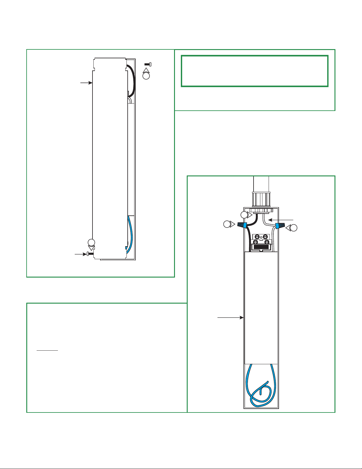
Install the Remote Transformer
A
TRANSFORMER COVER
NOTE: In order to use small gauge wires from the transformer
to the electrical box, it is recommended to install the remote
1
transformers as near as possible to the electrical box. See "Low
Voltage Wire Size Chart" on page 3.
1:
Loosen and remove the two Phillips screws on the sides of
the transformer to remove the transformer cover.
B
3
6
CONDUIT
7
1
PHILLIPS SCREW
2: Secure the transformer housing in place (hardware not
included).
3: Install a conduit and power wires from the panel to the
transformer.
4: DO NOT connect the power wires to the panel at this time.
5: Ground the transformer housing in accordance with local
electrical codes.
6: Connect the 120V black transformer wire to the hot power
with a wire nut.
7: Connect the 120V white transformer wire to the neutral
power with a wire nut.
TRANSFORMER
HOUSING
2
Page 3
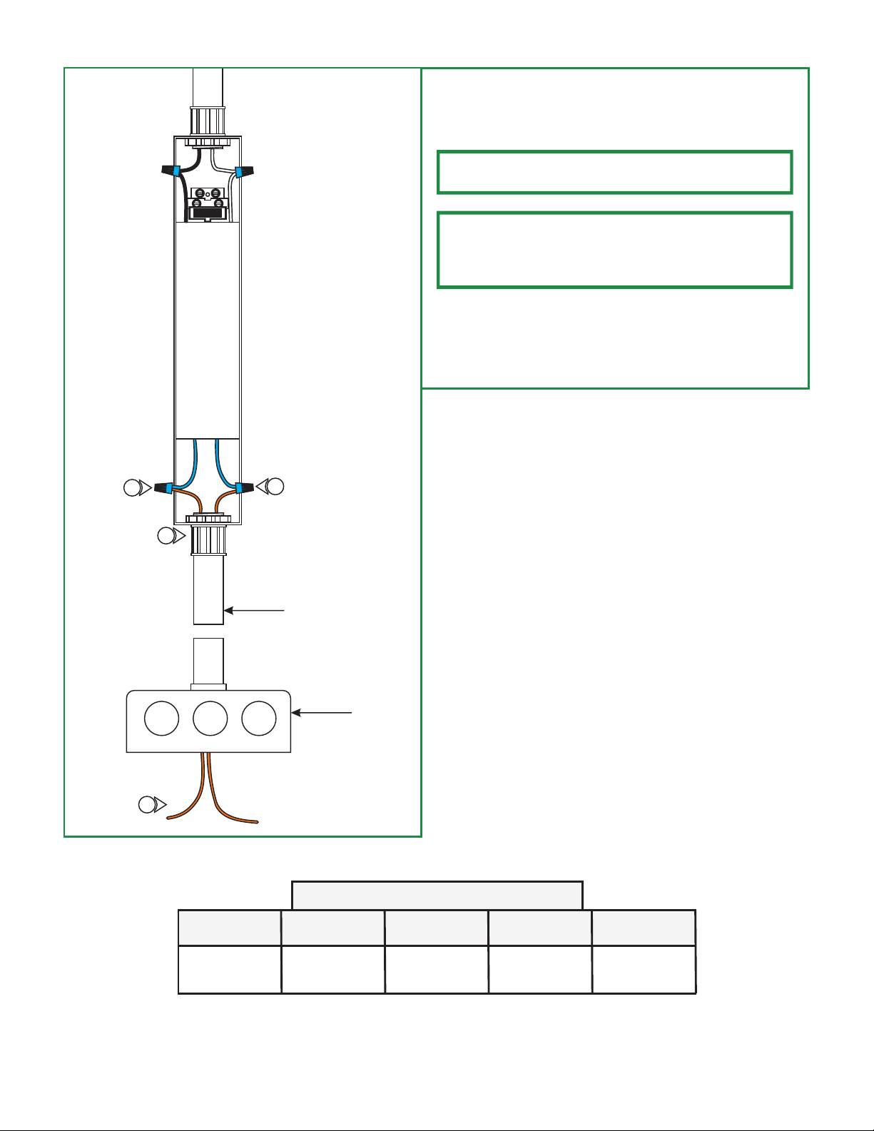
C
8: Install a conduit from the transformer to the electrical box.
9: For the best performance, use the "Low Voltage Wire Size
Chart" below to select the wire size.
NOTE: Using a smaller wire size other than specified will result in
a increase in voltage drop and will reduce the lamp intensity.
NOTE: The THHN wire sizes specified in "Low Voltage Wire Size
Chart" are for 3% or less drop in voltage based on 300 watt
loads. Lengths are the distance from the remote transformer to
the system power feed connector, or power feed canopy.
10: Install the THHN low voltage wires from the transformer to
the electrical box where the power feed will be installed.
11: Connect one blue transformer wire to each low voltage wire
with a wire nut.
11
11
8
CONDUIT
ELECTRICAL
BOX
10
LOW VOLTAGE WIRE SIZE CHART
TRANSFORMER
WATTAGE
WIRE SIZE
FOR 5 FT
WIRE SIZE
FOR 6-15 FT
WIRE SIZE
FOR 16-20 FT
WIRE SIZE
FOR 21-40 FT
300 WATT #10 GA #6 GA #4 GA #1 GA
3
Page 4
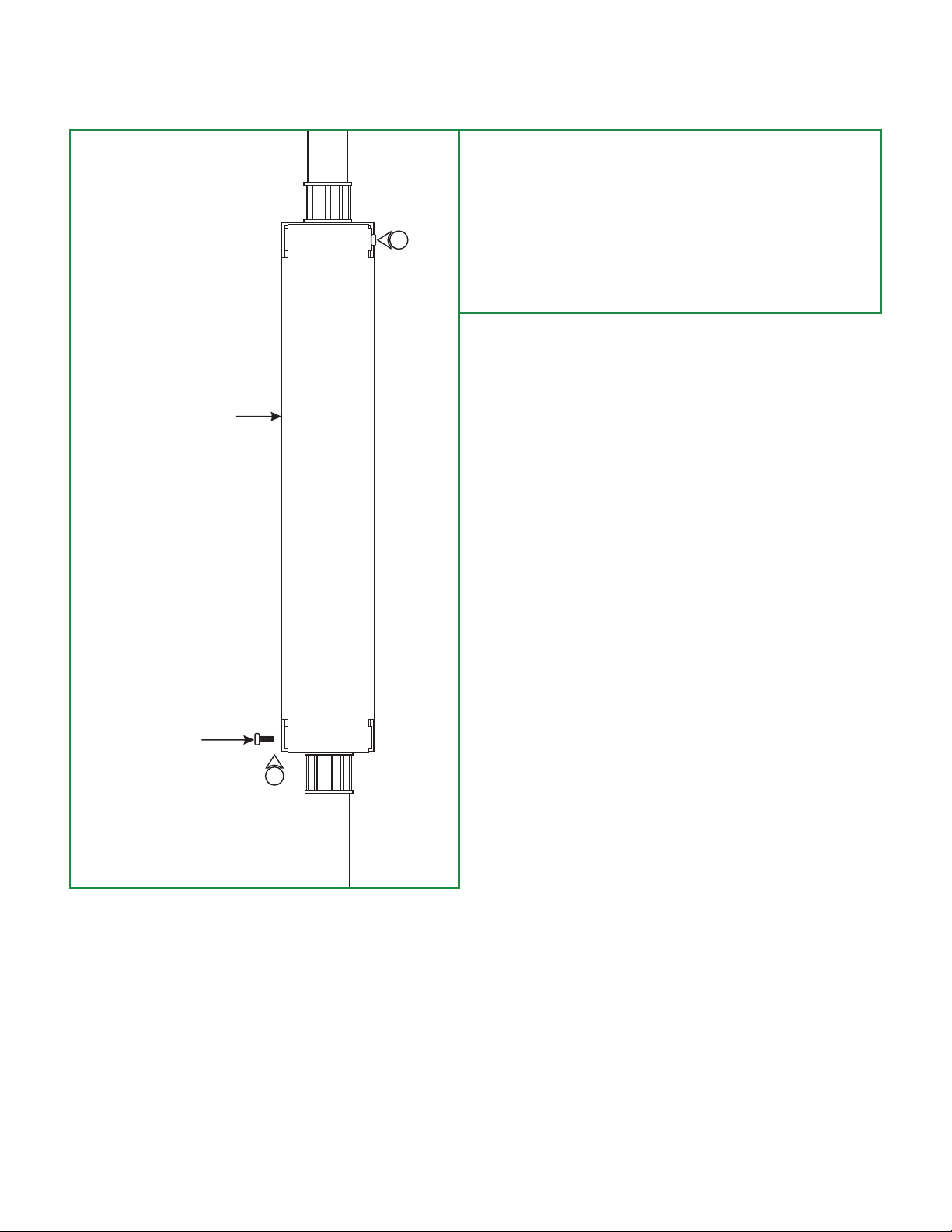
D
TRANSFORMER COVER
14
12: Connect the 120 volt power line wires at the panel.
13: After operating the system for a few minutes, on the low
voltage side, all electrical connection points should be no
more than warm to the touch. If a connection is hot to the
touch, retighten the connection and check to ensure that
the temperature decreases.
14: Replace the transformer cover and tighten the two Phillips
screws on the sides of the transformer.
PHILLIPS SCREWS
14
4
 Loading...