


EDAN Agile PLM Electronic Signature Information
--Signatures related to this document and performed in EDAN Agile PLM.
(Document Name) iM50 _(Number) 01.54.455510(Version) 1.3
(Product Model) iM50;M50(Project Code) 2711I000
(Signature):
(Originator) : , (wuxiaoping) |
|
|
|
|||||
|
2015-09-09 11:15:10 |
|||||||
|
|
CONFIDENTIAL |
||||||
(Reviewers) : , (mengxiaohui) |
2015-09-10 08:42:42 |
|||||||
(Reviewers) : , (hanjideng) |
|
|
||||||
|
2015-09-14 14:11:47 |
|||||||
(Reviewers) : , (leibinbin) 2015-09-09 13:13:17 |
||||||||
|
|
|
|
|
|
2015-09-09 16:49:18 |
||
(Reviewers) : , (chenhaojie) |
||||||||
(Reviewers) : , (gexiao) |
2015-09-09 11:27:34 |
|||||||
|
|
|
|
|
|
|
|
|
(Reviewers) : , (chengzhaochi) 2015-09-09 11:20:43 |
||||||||
(Reviewers) : , (qinzhao) |
2015-09-10 13:03:26 |
|||||||
|
|
|
|
|
|
2015-09-11 16:03:48 |
||
(Reviewers) : , (xiahuanhuan) |
||||||||
(Reviewers) : , (dingpengyu) |
2015-09-09 11:16:25 |
|||||||
|
|
|
|
|
|
|
2015-09-18 11:35:00 |
|
(Approvers) : , (xiahuanhuan) |
||||||||
(Approvers) : , (chenhaojie) |
2015-09-15 08:49:46 |
|||||||
EDAN |
|
|
|
|
|
|
|
|
© (Copyright©Edan Instrument,Inc.)

|
|
|
|
|
CONFIDENTIAL |
||||
|
|
|
|
|
|
|
|
|
|
|
|
|
|
|
EDAN |
|
|
|
|

About this Manual
P/N: 01.54.455510
MPN: 01.54.455510013
Release Date: September, 2015
© Copyright EDAN INSTRUMENTS, INC. 2012-2015. All rights reserved.
Statement
This manual will help you understand the operation and maintenance of the product better. It is
EDAN owns the copyrights of this manual. Without prior written consent of ED N, any materials contained in this manual shall not be photocopied, reproduced or translated into other languages.
reminded that the product shall be used strictly complying with this manual. User’s operation
failing to comply with this manual may result in malfunction or accident for which EDAN INSTRUMENTS, INC. (hereinafter called EDAN) cannot be held liable.
such as technical information and patent information are contained in this manual, the user shall not disclose such information to any irrelevant third party.
Materials protected by the copyright law, including but not limited to confidential information
The user shall understand that nothing in this manual grants him, expressly or implicitly, any right or license to use any of the intellectual properties of E AN.
EDAN holds the rights to modify, update, and ultimately explain this manual.
Responsibility of the Manufacturer
|
|
Assembly operations, extensions, re-adjustments, modifications or repairs are carried out by |
|
persons authorized by EDAN, and |
|
|
CONFIDENTIAL |
The electrical installation of the relevant room complies with national standards, and |
|
The instrument is used in accordance with the instructions for use. |
|
EDAN only considers itself responsible for any effect on safety, reliability and performance of the equipment if:
UponEDANrequest, EDAN may provide, with compensation, necessary circuit diagrams, and other information to help qualified technician to maintain and repair some parts, which EDAN may define as user serviceable.
I

Terms Used in this Manual
This guide is designed to give key concepts on safety precautions.
WARNING
A WARNING label advises against certain actions or situations that could result in personal injury or death.
CAUTION
A CAUTION label advises against actions or situations that could damage equipment, produce inaccurate data, or invalidate a procedure.
NOTE |
|
|
|
|
|
|
|
|
|
|
|
|
|
A NOTE provides useful information regarding a function or a procedure. |
||||||
|
|
CONFIDENTIAL |
||||
|
|
|
|
|
|
|
|
|
|
|
|
|
|
|
|
|
|
|
||
EDAN |
|
|
|
|
|
|
II

|
|
|
|
Table of Contents |
|
|||
Chapter 1 Warranty and Service.............................................................................................. |
|
|
|
1 |
||||
Chapter 2 Safety Guidance ....................................................................................................... |
|
|
|
|
4 |
|||
2.1 |
Introduction .................................................................................................................... |
|
|
|
|
|
4 |
|
2.2 |
General Information........................................................................................................ |
|
|
|
|
|
4 |
|
2.3 |
Safety Precautions .......................................................................................................... |
|
|
|
|
|
4 |
|
2.4 |
Explanation of Symbols on the Monitor.......................................................................... |
|
|
6 |
||||
Chapter 3 Installation ............................................................................................................. |
|
|
|
|
|
10 |
||
|
|
|
|
|
|
|
|
|
3.1 |
Environment Requirements........................................................................................... |
|
|
|
10 |
|||
3.2 |
Electrical Requirements ................................................................................................ |
|
|
|
10 |
|||
|
|
|
CONFIDENTIAL |
|
||||
3.3 |
Safety Requirements ...................................................................................................... |
|
|
|
|
11 |
||
|
|
|
|
|
|
|
|
|
3.4 |
Installing the Monitor .................................................................................................... |
|
|
|
|
11 |
||
3.5 |
Connecting to AC Power .............................................................................................. |
|
|
|
12 |
|||
Chapter 4 Test and Maintenance ............................................................................................ |
|
|
|
13 |
||||
4.1 |
Routine Test.................................................................................................................. |
|
|
|
|
|
13 |
|
|
4.1.1 Visual Inspection................................................................................................. |
|
|
|
13 |
|||
|
|
|
|
|
|
|
|
|
|
4.1.2 Poweron Test .................................................................................................... |
|
|
|
|
13 |
||
|
4.1.3 Key Test.............................................................................................................. |
|
|
|
|
|
13 |
|
|
4.1.4 Recording Test .................................................................................................... |
|
|
|
|
13 |
||
|
4.1.5 Alarm Test........................................................................................................... |
|
|
|
|
|
14 |
|
4.2 |
Functional Tests and Accuracy Tests ............................................................................. |
|
|
14 |
||||
|
|
|
|
|
|
|
|
|
|
4.2.1 ECG Functional Test ........................................................................................... |
|
|
|
14 |
|||
|
4.2.2 SpO2 |
Functional Test........................................................................................... |
|
|
|
15 |
||
|
4.2.3 NIBP Functional Test .......................................................................................... |
|
|
|
15 |
|||
|
4.2.4 NIBP Leakage Test.............................................................................................. |
|
|
|
16 |
|||
|
4.2.5 NIBP Accuracy Test ............................................................................................ |
|
|
|
16 |
|||
|
4.2.6 IBP Calibration................................................................................................. |
|
|
|
17 |
|||
|
4.2.7 TEMP Accuracy Test........................................................................................... |
|
|
|
18 |
|||
|
4.2.8 CO2 Functional Test ............................................................................................ |
|
|
|
19 |
|||
|
4.2.9 IBP Functional Test ............................................................................................. |
|
|
|
19 |
|||
4.3 |
Safety Test ................................................................................................................... |
|
|
|
|
|
|
19 |
|
4.3.1 Safety Test Procedures ........................................................................................ |
|
|
|
19 |
|||
EDAN4.3.2 Protective Earth Resistance ................................................................................. |
|
|
20 |
|||||
III

|
4.3.3 Enclosure Leakage Current ................................................................................. |
|
|
21 |
||||
|
4.3.4 Patient Leakage current ....................................................................................... |
|
|
|
22 |
|||
|
4.3.5 Patient Leakage CurrentSingle Fault Condition (S.F.C) Mains on Applied Part . 24 |
|||||||
4.4 Maintenance................................................................................................................ |
|
|
|
|
|
25 |
||
|
4.4.1 Cleaning the Monitor and Accessories................................................................. |
|
25 |
|||||
|
4.4.2 Maintaining the Battery....................................................................................... |
|
|
|
25 |
|||
Chapter 5 Configuration......................................................................................................... |
|
|
|
|
|
26 |
||
5.1 |
Opening User Maintain Menu....................................................................................... |
|
|
|
26 |
|||
5.2 |
Entering Demo Mode ................................................................................................... |
|
|
|
|
26 |
||
5.3 |
Selecting Lead Style |
..................................................................................................... |
|
|
|
|
26 |
|
|
|
|
|
|
|
|
|
|
5.4 |
Changing the Bed No.................................................................................................... |
|
|
|
|
27 |
||
5.5 |
Network Setup.............................................................................................................. |
|
|
|
|
|
27 |
|
|
|
|
CONFIDENTIAL |
|
||||
|
|
|
|
|
|
|
|
|
Chapter 6 Principle Introduction ........................................................................................... |
|
|
|
28 |
||||
6.1 |
System Principle Block Diagram |
.................................................................................. |
|
|
28 |
|||
|
6.1.1 Main Control Board ............................................................................................ |
|
|
|
28 |
|||
|
|
|
|
|
|
|
|
|
|
6.1.2 Key Board........................................................................................................... |
|
|
|
|
|
30 |
|
|
6.1.3 Screen Drive Board............................................................................................. |
|
|
|
31 |
|||
|
|
|
|
|
|
|
|
|
|
6.1.4 Interface Board ................................................................................................... |
|
|
|
|
31 |
||
|
6.1.5 Power Module..................................................................................................... |
|
|
|
|
31 |
||
6.2 |
Interfaces ...................................................................................................................... |
|
|
|
|
|
|
32 |
|
|
|
|
|
|
|
|
|
Chapter 7 Troubleshooting |
..................................................................................................... |
|
|
|
|
33 |
||
7.1 |
Monitor Booting Failures.............................................................................................. |
|
|
|
33 |
|||
|
|
|
|
|
|
|
|
|
7.2 |
Display Failures............................................................................................................ |
|
|
|
|
|
34 |
|
7.3 |
Operation Failures ........................................................................................................ |
|
|
|
|
|
34 |
|
7.4 |
Recorder Failures.......................................................................................................... |
|
|
|
|
|
35 |
|
7.5 Alarm Failures .............................................................................................................. |
|
|
|
|
|
36 |
||
7.6 |
Parameter Monitoring Failures...................................................................................... |
|
|
|
37 |
|||
EDAN |
|
|
|
|
|
|
||
7.7 Technological Alarms ................................................................................................... |
|
|
|
|
39 |
|||
Chapter 8 Disassembling the Monitor.................................................................................... |
|
|
|
40 |
||||
8.1 Tools Required.............................................................................................................. |
|
|
|
|
|
40 |
||
8.2 |
Replacing Fuses............................................................................................................ |
|
|
|
|
|
40 |
|
8.3 |
isassembling the Main Unit ........................................................................................ |
|
|
|
41 |
|||
8.4 |
Disassembling the Front Housing Assembly |
................................................................. |
|
42 |
||||
|
8.4.1 Replacing the Touch Screen or Protective Screen ................................................ |
42 |
||||||
IV

8.4.2 Replacing the LCD.............................................................................................. |
|
|
|
43 |
|||
8.4.3 Replacing the Silicone Keys................................................................................ |
|
|
43 |
||||
8.4.4 Replacing the Key Board .................................................................................... |
|
|
|
43 |
|||
8.4.5 Replacing the Knob............................................................................................. |
|
|
|
43 |
|||
8.4.6 Replacing the Display Drive Board or Touch Screen Commutator....................... |
43 |
||||||
8.4.7 Replacing the Alarm Indicator Board .................................................................. |
|
|
44 |
||||
8.5 Disassembling the Main Frame Assembly..................................................................... |
|
|
44 |
||||
8.5.1 Replacing the Power Module .............................................................................. |
|
|
45 |
||||
8.5.2 Replacing the Fan and Speaker............................................................................ |
|
|
46 |
||||
8.5.3 Replacing CO2 Module, IBP Module and Nellcor Module................................... |
46 |
||||||
|
|
|
|
|
|
|
|
8.5.4 Replacing the Main Board................................................................................... |
|
|
|
47 |
|||
8.5.5 Replacing the Pump&Valve Assembly ................................................................ |
|
47 |
|||||
|
|
CONFIDENTIAL |
|
||||
8.5.6 Replacing the Battery Interface Board ................................................................. |
|
48 |
|||||
|
|
|
|
|
|
|
|
8.5.7 Replacing the Main Unit Interface Board ............................................................ |
|
49 |
|||||
8.5.8 Replacing the SD Card Commutator ................................................................... |
|
|
49 |
||||
|
|
|
|
|
|
|
|
8.5.9 Replacing the Recorder ....................................................................................... |
|
|
|
49 |
|||
8.5.10 Replacing EDAN EtCO2 Module ...................................................................... |
|
|
50 |
||||
Appendix 1 Replaceable Parts ................................................................................................ |
|
|
|
51 |
|||
|
|
|
|
|
|
|
|
|
|
|
|
|
|
|
|
EDAN |
|
|
|
|
|
|
|
V

iM50/M50 Patient Monitor Service Manual |
Warranty and Service |
Chapter 1 Warranty and Service
Standard Service
EDAN provides a one-year-warranty for the warranted products (accessories are included). The warranty period begins on the date the products are shipped to customers. If a customer promptly notifies EDAN of customer’s warranty claim hereunder, EDAN will either repair, adjust or replace (with new or exchange replacement parts) EDAN’s products. EDAN warrants that any service it provides to customers will be performed by trained individuals in a workmanlike manner.
Limitation of Warranty
Direct, indirect or final damage and delay caused by the following situations for which EDAN is not responsible may void the warranty:
Groupware is dismounted, stretched or redebugged. |
|
||
|
Unauthorized modification or misuse. |
||
|
|||
Damage caused by operating beyond the environmental specifications for the medical |
|
|
|
product.
Change or remove original serial number label or Manufacturer symbol.
Improper use.
(1)Fill in the Service Claim Form (SCF).
Fill in the SCF with detailed information including: Model Name, Serial Number (SN) and
Problem Phenomena.
EDAN should not have any obligation to take over the case without this information. The form can be downloaded at: http://www.edan.com.cn or obtained from EDAN’s Service Department.
(2)Send EDAN the SCF and Select a Solution.
Once the service department receives the fully filled SCF, EDAN’s engineer will offer a
solution in three working days. EDAN will follow out the case based on the two conditions
below: CONFIDENTIALEDAN
Within Warranty:
There are two options:
-1-

iM50/M50 Patient Monitor Service Manual |
Warranty and Service |
i)After receiving the Return Material Authorization (RMA) form from EDAN service department, the customer sends EDAN the defective parts and informs about the shipment tracking number. Then we will dispatch new part(s) to your confirmed address with confirmed shipping invoice.
ii)The customer signs the Declaration Form and sends it back by email or fax. This form is legally certificated to make sure the customer or end-user will return the defective parts to EDAN on time. We will, at this option, dispatch the replacement one(s) with confirmed shipping invoice.
NOTES:
(1) Both Return Material Authorization Form and Declaration Form are offered by
EDAN service department once the SCF is confirmed by service engineer.
(2) The customer is responsible for freight & insurance charges when the equipment |
|
is shipped to EDAN for service, including custom charges. ED N is responsible |
|
for the freight, insurance & custom charges from EDAN to the customer. |
|
Out of Warranty: |
|
|
|
After receiving the RMA form from the service department, the customer sends defective |
|
parts to EDAN in advance.CONFIDENTIALWe will analyze the problems and discuss with the customer about
either repairing or replacing the part(s). Once the maintenance fee is invoiced and paid, we will make sure to dispatch good part(s) to the confirmed address.
NOTE: The customer is responsible for any freight & insurance charge for the returned product.
(3) Obtain the RMA Form.
Before the shipment of the materials, the customer must obtain an RMA form from our service department, in which the RMA number, description of returning parts and shipping instructions are included. The RMA number should be indicated on the outside of the
shipping container.
NOTE:EDAN
EDAN should not have any obligation to the end-user or customer who returns the goods without the notification by EDAN’s service department. The sender takes full responsibility for the accounted fee.
(4) Send the Parts to EDAN.
-2-

iM50/M50 Patient Monitor Service Manual |
Warranty and Service |
Follow these recommended instructions:
Please disassemble the parts with anti-static facility, do not touch the parts with naked hand.
Please pack the parts safely before return.
Please put the RMA number on the parcel.
Please describe the returned parts as ‘sample of *****’ and put the total value on the invoice, and note on the invoice as ‘sample, no commercial value’.
Please confirm the invoice with EDAN before shipment.
Please send back the parts after EDAN’s confirmation.
Contact Information |
|
|
|
|
|
|
|
|
CONFIDENTIAL |
||||
If you have any question about maintenance, technical specifications or malfunctions of devices, |
||||||
do not hesitate to contact us. |
|
|
|
|
|
|
EDAN Instruments, Inc. |
|
|
|
|
|
|
TEL: +86-755-26898321, 26899221 |
|
|
|
|||
FAX: +86-755-26882223, 26898330 |
|
|
|
|||
E-mail: support@edan.com.cn |
|
|
|
|
||
|
|
|
|
|||
|
|
|
|
|
|
|
EDAN |
|
|
|
|
|
|
-3-
iM50/M50 Patient Monitor Service Manual |
Safety Guidance |
Chapter 2 Safety Guidance
2.1 Introduction
This service manual is a reference for periodic preventive maintenance and corrective service procedures for the iM50/M50 patient monitor. It provides information on troubleshooting, assembly procedures, and instructions for functional testing as well as performance verification. The manual is intended for use only by technically qualified service personnel.
WARNING
Please follow the instructions exactly in accordance with this manual during service.
iM50 Patient Monitor (hereinafter called monitor) is designed in accordance with the
Failure to do so might result in damage to the monitor or personal injury.
2.2 General Information
|
|
|
|
|
|
|
|
|
Anti-electroshock Type |
|
Class I equipment and internal powered equipment |
|
|||
|
|
|
|
|
|
|
|
|
Anti-electroshock Degree |
|
NIBP, SpO2, CO2 |
BF |
|
|
|
|
|
|
|
|
CF |
|
|
|
|
|
ECG(RESP), TEMP, IBP, Quick TEMP |
|
|||
|
|
|
|
|
|||
|
Ingress Protection |
|
IPX1 (No protection against ingress of water if |
|
|
||
|
|
configured with Quick TEMP module) |
|
|
|
||
|
Degree of Safety in Presence of |
Not suitable for use in presence of flammable gases |
|
|
|||
|
Flammable Gases |
|
|
|
|
|
|
|
|
|
|
|
|
|
|
|
Working System |
|
Continuous operation equipment |
|
|
|
|
2.3 |
|
|
|
|
|
|
|
Safety Precautions |
|
|
|
|
|
||
To avoid possible injury, pleaseCONFIDENTIALobserve the following precautions during the operation of the |
|||||||
instrument. |
|
|
|
|
|
|
|
EDAN |
|
|
|
|
|
|
|
|
|
|
|
|
|
|
|
international safety requirements in IEC/ EN 60601-1 for medical electrical equipment. Classification information of this equipment is as follows:
WARNING
1 The monitor must be serviced only by authorized and qualified personnel. EDAN does not assume any responsibility for damage or injury if modifications or repairs are carried out by unauthorized personnel.
-4-

iM50/M50 Patient Monitor Service Manual |
Safety Guidance |
WARNING
2Use and replace the substitutive parts provided or recommended by EDAN only.
3The service personnel must be familiar with the operation of this monitor. Refer to
Patient Monitor User Manual for details.
4Perform periodic safety test to ensure patient safety. Safety test should include leakage current measurement and insulation testing.
5Disconnect the monitor from power before replacing the fuses which are with the identical specifications.
6SHOCK HAZARD – Do not remove the top panel cover during operation or while power is on. The unit cover must be removed only by authorized service personnel.
7SHOCK HAZARD – Do not attempt to connect or disconnect the power cord with wet hands. Make sure that your hands are clean and dry before touching the power cord.
8Accessory equipment connectedCONFIDENTIALto the analog and digital interface must be certified according to the respective IEC/ EN standards (e.g. IEC/ EN 60950 for data processing equipment and IEC/ EN 60601-1 for medical equipment). Furthermore, all
configurations shall comply with the valid version of the system standard IEC/ EN 60601-1. Anybody who connects additional equipment to the signal input connector or signal output connector to configure a medical system must ensure that the system
complies with the requirements of the valid version of the system standard IEC/ EN
6060-1. If you have any question, please consult our technical service department or your local distributor.
9Do not remove the battery while AC power is on.
10Do not directly connect the battery to an electric outlet.
11Do not directly solder the lead wire and the batter terminal.
CAUTION
1The device is designed for continuous operation. Avoid splashing water over the device.
2Do not operate the device when it is damp or wet. Avoid using the device immediately after relocating it from a cold environment to a warm and humid environment.
3While the battery is charged, used or stored, keep it away from objects or materials with static electric charges.
EDAN
-5-
iM50/M50 Patient Monitor Service Manual |
Safety Guidance |
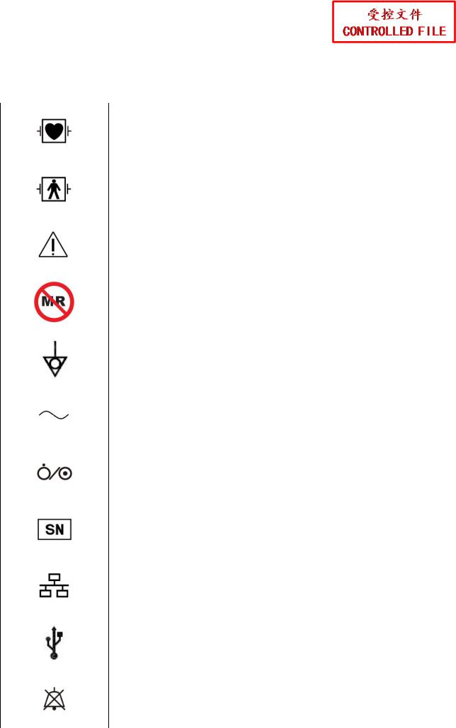
2.4 Explanation of Symbols on the Monitor
1 |
|
|
|
DEFIBRILLATION-PROOF TYPE CF APPLIED PART |
|||
|
|
|
|
||||
|
|
|
|
|
|
|
|
2 |
|
|
|
DEFIBRILLATION-PROOF TYPE BF APPLIED PART |
|||
|
|
|
|
||||
|
|
|
|
|
|
|
|
3 |
|
|
|
Caution |
|
|
|
|
|
|
|
|
|
||
|
|
|
|
|
|
|
|
|
|
|
|
|
|
|
|
4 |
|
|
|
CONFIDENTIAL |
|||
|
|
|
|
MR Unsafe |
|
|
|
5 |
|
|
|
|
|
|
|
|
|
|
|
|
|
||
|
|
|
|
Equipotential grounding |
|
||
|
|
|
|
|
|
|
|
7 |
|
|
|
|
|
|
|
6 |
|
|
|
Alternating Current |
|
||
|
|
|
|
Power Supply switch |
|
||
|
|
|
|
|
|
|
|
8 |
|
SERIAL UMBER |
|
||||
|
|
||||||
|
|
|
|
|
|
|
|
|
|
|
|
|
|
|
|
9 |
|
|
|
Network port |
|
|
|
|
|
|
|
|
|
||
|
|
|
|
|
|
|
|
EDAN |
|
|
|
|
|
||
10 |
|
|
|
USB (Universal Serial Bus) Connection |
|||
11 |
|
|
|
Bell cancel – AUDIO OFF |
|
||
|
|
|
|
|
|||
|
|
|
|
|
|
|
|
-6-

iM50/M50 Patient Monitor Service Manual |
Safety Guidance |
12 |
NIBP measurement |
|
13 |
Trend |
|
14 |
Picture freeze |
|
15 |
|
|
|
Graphical recorder |
|
|
|
|
|
|
|||
|
|
|
|
|
||
|
|
|
|
|||
21 |
|
|
CONFIDENTIALOutput |
|||
16 |
|
|
|
Menu |
|
|
17 |
|
|
|
Video output |
|
|
18 |
|
|
|
|
|
|
|
|
|
|
Nurse call port |
|
|
19 |
|
|
Write data into store |
|
||
|
|
|
|
|||
|
|
|
|
|
||
20 |
|
|
Defibrillator synchronization/Signal output port |
|||
|
|
|
||||
|
|
|
|
|||
|
|
|
|
|
||
|
|
|
|
|
||
EDAN |
|
|
|
|
||
22 |
|
|
|
CE marking |
|
|
|
|
|
|
|
|
|
-7-

iM50/M50 Patient Monitor Service Manual
23
24
25
26
27
28
29
30 |
|
|
31 |
||
|
Safety Guidance
IN THE

iM50/M50 Patient Monitor Service Manual |
Safety Guidance |
34 |
Gas outlet (evac) |
|
35 |
|
Ingress |
Protection |
IPX1 (Protected |
against vertically |
|||||
|
falling water drops) |
|
|
|
||||||
|
|
|
|
|
|
|||||
|
|
|
|
|||||||
36 |
|
Caution: Federal (U.S.) Law restricts this device to sale by |
||||||||
|
or on the order of a physician. |
|
||||||||
|
|
|
|
|||||||
|
|
|
|
|
||||||
|
|
|
With respect |
to electrical shock, fire and mechanical |
||||||
|
|
|
hazards |
only |
|
in |
|
|
UL 60601-1and |
|
37 |
|
CAN/CSA C22.2 No. 601.1, IEC 60601-2-27, IEC |
||||||||
|
|
CONFIDENTIAL |
||||||||
|
|
|
60601-2-30,IEC 60601-2-34, IEC 60601-2-49 |
|||||||
NOTE: |
|
|
|
|
|
|
|
|
||
The service manual is printed in black and white. |
|
|
|
|||||||
|
|
|
|
|
|
|
|
|
||
|
|
|
|
|
|
|
|
|
|
|
|
|
|
|
|
|
|
|
|
|
|
|
EDAN |
|
|
|
|
|
|
|
|
|
-9-

iM50/M50 Patient Monitor Service Manual |
Installation |
Chapter 3 Installation
WARNING
Only qualified service engineers should install this equipment.
3.1 Environment Requirements
Working |
|
|
|
|
|
|
|
|
|
|
|
||
Temperature |
|
|
|
0 ºC ~ 40 ºC(32 ~104 ) |
||
|
|
|
|
|
|
|
Relative Humidity |
|
|
|
|
|
|
|
|
|
15%RH ~ 95%RH (non-condensing) |
|||
Atmospheric Pressure |
CONFIDENTIAL |
|||||
|
|
86 kPa ~ 106 kPa |
||||
Storage |
|
|
|
|
|
|
Temperature |
|
|
|
-20 ºC ~ 55 ºC(-4 ~131 ) |
||
Relative Humidity |
|
|
|
|
|
|
|
|
|
15%RH ~ 95%RH (non-condensing) |
|||
Atmospheric Pressure |
|
|
70 kPa ~ 106 kPa |
|||
NOTE: |
|
|
|
|
|
|
|
|
|
|
|||
1 Do not install the monitor in close proximity to flammable anesthetics. |
||||||
2 Keep the environment clean and keep the device away from corrosive medicine. |
||
|
|
|
Prevent the device from vibration, high temperature, humidity and exposure to the |
||
sun. |
|
|
3.2 Electrical Requirements |
|
|
|
|
|
Operating Voltage |
100 V-240 V ~ |
|
|
|
|
EDAN |
50 Hz/60 Hz |
|
Operating Frequency |
||
Input Current |
1.0 A-0.5 A |
|
-10-
iM50/M50 Patient Monitor Service Manual |
Installation |
3.3 Safety Requirements
|
|
CAUTION |
|
|
1 |
SHOCK HAZARD – To protect patients and medical staff, the power receptacle must |
|||
|
be well grounded. Never adapt |
the three-prong plug from the monitor to fit a |
||
|
two-socket outlet. |
|
|
|
2 |
Do not simultaneously touch the signal input or output connector and the patient. |
|||
3 |
The monitor and equipment connected to the monitor should be equipotential to |
|||
|
ensure effective grounding. |
|
|
|
4 |
Do not switch on the monitor until all units and accessories have been properly |
|||
|
connected and verified. |
|
|
|
|
|
|||
|
CONFIDENTIAL |
|||
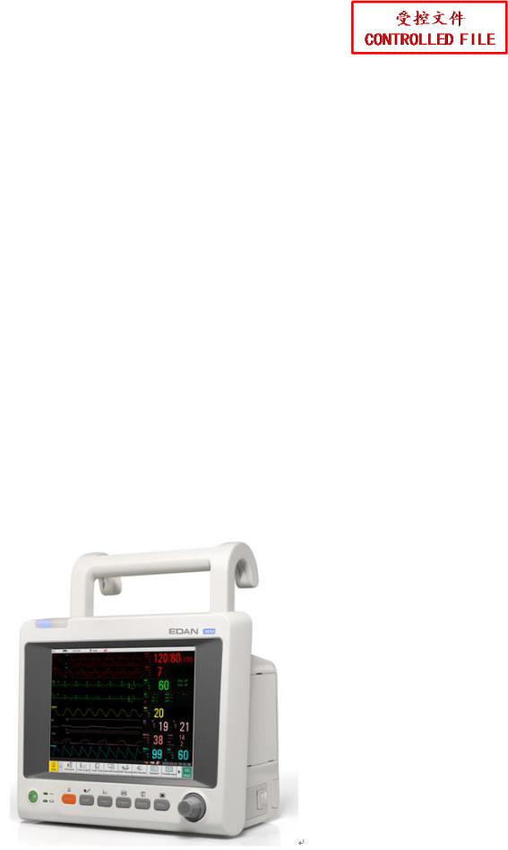
3.4 Installing the Monitor |
|
|
|
|
- To install the monitor on a flat surface. |
|
|
||
Place the monitor on a flat surface. Make sure the surface does not vibrate, and is free of
corrosive medicine and dust. |
|
|
|
|
|
EDAN |
iM50 on a Flat Surface |
|
-11-
 Loading...