

Ecler WPNET Series, WPNET8K, WPNET4KV, WPNETEX User Manual
WPNET wall panel series:
WPNET4KV – WPNET8K -WPNETEX
REMOTE CONTROLERS AND INTERFACES
Digital wall control
USER MANUAL

INDEX
1. IMPORTANT REMARK .......................................................................................................... 4
2. IMPORTANT SAFETY INSTRUCTIONS ............................................................................. 4
3. IMPORTANT NOTE ................................................................................................................ 6
4. INTRODUCTION ..................................................................................................................... 6
4.1. Main features ............................................................................................................................... 6
5. INSTALLATION ....................................................................................................................... 7
5.1. Installation of a single WPNET4KV, WPNET8K or WPNETEX unit, on surface or
flush: ....................................................................................................................................................... 7
5.2. Installation of a pair of adjacent WPNET4KV and WPNET8K panels, on surface
or flush: .................................................................................................................................................. 7
5.3. Installing an External Power Supply..................................................................................... 8
6. UNIT MANAGEMENT in standard or individual mode (*) .............................................. 9
6.1 Unit WPNET4KV management .............................................................................................. 9
6.2 Unit WPNET8K management ............................................................................................... 13
6.3 Unit WPNET12KV management.......................................................................................... 16
6.4 Unit WPNETEX management ............................................................................................... 17
6.4.1 Preset selection .................................................................................................................. 19
6.4.2. Selecting Sources ............................................................................................................. 21
6.4.3. Equalization settings ........................................................................................................ 23
6.4.4. Volume setting / MUTE ................................................................................................... 24
6.5 Units WPNET4KV or WPNET12KV operation in MULTI MODE ............................... 25
7. NOTES: .................................................................................................................................... 31
8. FRONT PANEL ...................................................................................................................... 31
8.1. WPNET4K / EX ......................................................................................................................... 31
8.1. WPNET8K .................................................................................................................................. 31
9. REAR PANEL ......................................................................................................................... 32
2

10. BLOCK DIAGRAM ................................................................................................................. 33
10.1. WPNET4KV / EX .................................................................................................................... 33
10.2. WPNET8K ................................................................................................................................ 33
11. TECHNICAL FEATURES ...................................................................................................... 34
11.1. WPNET4KV / EX .................................................................................................................... 34
11.2. WPNET8K ................................................................................................................................ 34
12. ASSEMBLY DIAGRAM ......................................................................................................... 35
13. PACKAGE CONTENTS ........................................................................................................ 36
3
1. IMPORTANT REMARK
The lightning flash with arrowhead symbol, within an equilateral triangle, is
intended to alert the user to the presence of uninsulated “dangerous
voltage” within the product’s enclosure that may be of sufficient magnitude
to constitute a risk of electric shock to persons.
The exclamation point within an equilateral triangle is intended to alert the
user to the presence of important operating and maintenance (servicing)
instructions in the literature accompanying the appliance.
WARNING (If applicable): The terminals marked with symbol of “ ”
may be of sufficient magnitude to constitute a risk of electric shock. The external wiring
connected to the terminals requires installation by an instructed person or the use of
ready-made leads or cords.
WARNING: To prevent fire or shock hazard, do not expose this equipment to rain or
moisture..
WARNING: An apparatus with Class I construction shall be connected to a mains
socket-outlet with a protective earthing connection.
2. IMPORTANT SAFETY INSTRUCTIONS
1. Read these instructions.
2. Keep these instructions
3. Heed all warnings
4. Follow all instructions
5. Do not use this apparatus near water
6. Clean only with dry cloth
7. Do not block any ventilation openings Install in accordance with the
manufacturer’s instructions
4

8. Do not install near any heat sources such as radiators, heat registers, stoves, or
other apparatus (including amplifiers) that produce heat.
9. Do not defeat the safety purpose of the polarized or grounding type plug. A
polarized plug has two blades with one wider than the other. A grounding type
plug has two blades and a third grounding prong. The wide blade and the third
prong are provided for your safety. If the provided plug does not fit into your
outlet, consult an electrician for replacement of the obsolete outlet.
10. Protect the power cord from being walked on or pinched particularly at the
plugs, convenience receptacles, and at the point where they exit from the
apparatus.
11. Only use attachments/accessories specified by the manufacturer.
12. Unplug the apparatus during lightening sorts or when unused for long periods of
time.
13. Refer all servicing to qualified personnel. Servicing is required when the
apparatus has been damaged in any way, such as power supply cord or plug is
damaged, liquid has been spilled or objects have fallen into the apparatus, the
apparatus has been exposed to rain or moisture, does not operate normally, or
has been dropped.
14. Disconnecting from mains: switching off the POWER switch all the functions
and light indicators of the amplifier will be stopped, but fully disconnecting the
device from mains is done unplugging the power cord from the mains input
socket. For this reason, it always shall remain readily operable.
15. Equipment is connected to a socket-outlet with earthing connection by means of
a power cord.
16. The marking information is located at the bottom of the apparatus.
17. The apparatus shall not be exposed to dripping or splashing and that no objects
filled with liquids, such as vases, shall be placed on apparatus.
WARNING: This product must not be discarded, under any circumstance, as
unsorted urban waste. Take it to the nearest electrical and electronic waste
treatment centre.
NEEC AUDIO BARCELONA, S.L. accepts no liability for any damage that may be
caused to people, animal or objects due to failure to comply with the warnings above.
5

3. IMPORTANT NOTE
Thank you for choosing our digital wall control WPNET series.
It is VERY IMPORTANT to carefully read this manual and to fully understand its
contents before any connection in order to maximize your use and get the best
performance from this equipment.
To ensure optimal operation of this device, we strongly recommend that its maintenance
be carried out by our authorised Technical Services.
The WPNET series of digital controllers have a warranty of 3 years.
4. INTRODUCTION
WPNET4KV, WPNET8K and WPNETEX are digital wall controls, MIMO4040DN
compatible, configurable through the EclerNet Manager application (*).
(*) Refer to the EclerNet Manager Application manual for more information. The
EclerNet Manager application is available for download at www.ecler.com.
They allow remote control functions over MIMO4040DN, such as audio source selection,
volume adjustment, preset selection, etc.
4.1. Main features
Single European electrical box format, compatible with flush and surface
installation (surface box supplied as standard)
Power over Ethernet (PoE) or optional external power supply, WP-PSU model
Ethernet communication interface, RJ45 connector
128x128 pixels LCD display
Digital rotary control (encoder) + 4 programmable keys: 4KV and EX models
8 programmable keys: model 8K
MIMO4040DN matrix remote control functions: audio source selection, preset
selection, volume / MUTE adjustment, equalization settings, etc. (depending on
models, refer to this manual and the EclerNet Manager application manual)
6

5. INSTALLATION
The installation of the WPNET4KV, WPNET8K or WPNETEX units comprises the
following steps.
5.1. Installation of a single WPNET4KV, WPNET8K or WPNETEX unit, on surface or flush:
1. Remove the trim frame and front panel cover, held in place by magnets. You
can use the magnet provided as a tool, by making contact in the upper right
corner of the cover and gently pulling on it.
2. Connect the RJ-45 connector on the CAT5 or higher cable that will connect
the unit to the local installation network. If necessary - see note below connect external power.
3. Screw the device to the surface box or flush box.
4. Replace the frame and front panel and secure the rotary encoder knob.
Note: It is possible to use an adjacent pair of panels, consisting of a 4KV unit and an 8K
unit, becoming a new single panel of greater dimensions and number of available
controls for programming purposes and remote control possibilities, model
WPNET12KV. A double WPa2FMBOX box is required to flush both devices together, or
a double WPa2SMBOX box for surface mounting. Both, the WPa2FMBOX and
WPa2SMBOX are sold separately.
5.2. Installation of a pair of adjacent WPNET4KV and WPNET8K panels, on surface or flush:
1. Remove frames and front panel covers from both devices (WPNET4KV and
WPNET8K), held in place by magnets. You can use the magnet provided as a
tool, by making contact in the upper right corner of the cover and gently pulling
on it.
2. Interconnect with the two hoses (supplied as standard with the 8K unit) the
following point to point connectors between the two devices:
o J102 (3-wire hose)
o J107 (2-wire hose)
3. Connect the RJ-45 connector of the CAT5 cable or higher that will connect the
unit to the local network of the installation to the WPNET4KV unit, which will act
as the master unit of the two panels. Do not connect another CAT5 cable to the
WPNET8K unit. If necessary - see note below - connect external power supply.
7

4. Screw the devices to the double surface box or flush box.
5. Mount the WPa2SMBOX or WPa2FMBOX double frame.
6. Replace the front panels and secure the knob of the rotary encoder..
WPNET4KV + WPNET8K connection diagram = WPNET12KV
(rear view of printed circuit boards)
5.3. Installing an External Power Supply
In case of not having a PoE type power received in the control panel directly from the
connection port of the network switch to which it is connected, it is possible to power
the panel through an optional external power supply, model WP-PSU:
External power supply connection (rear view of the printed circuit board)
8

6. UNIT MANAGEMENT in standard or individual mode (*)
6.1 Unit WPNET4KV management
(*) Note: This section deals with the operation of a WPNET4KV unit in standard or
individual mode, being able to take control of a zone of the installation. It is also possible
to use it in “MULTI” mode, being able to take control of more than one zone. Please,
refer to the section Unit WPNET4KV or 12KV operation in MULTI MODE for more
information.
WPNET4KV has the following possible remote control functions on a MIMO4040DN
unit, programmed from the EclerNet Manager application:
Selecting sources or presets from a preset list in the EclerNet project
Adjusting the volume of a preset signal in the EclerNet project
MUTE ON/OFF of the same previous signal, preset in the EclerNet project
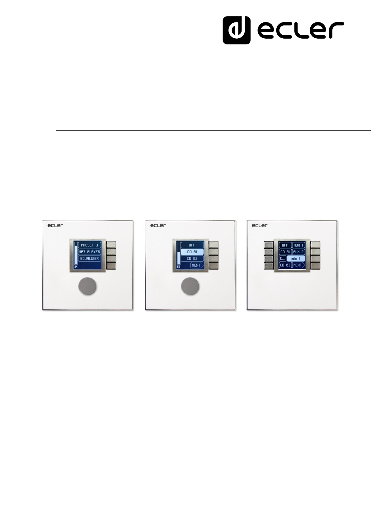
Front panel controls / on-screen information
In the previous image on the front panel, the available physical controls are:
K1 to K4: keys directly associated with adjacent functions displayed on the screen
K5: digital rotary control, or encoder, with rotary and pulsation functions
And the information fields shown on the screen are:
S1 to S4: text fields 1 to 4
S5: Adjusted volume indicator (signal level)
S6: textual value of the adjusted volume (signal level)
9
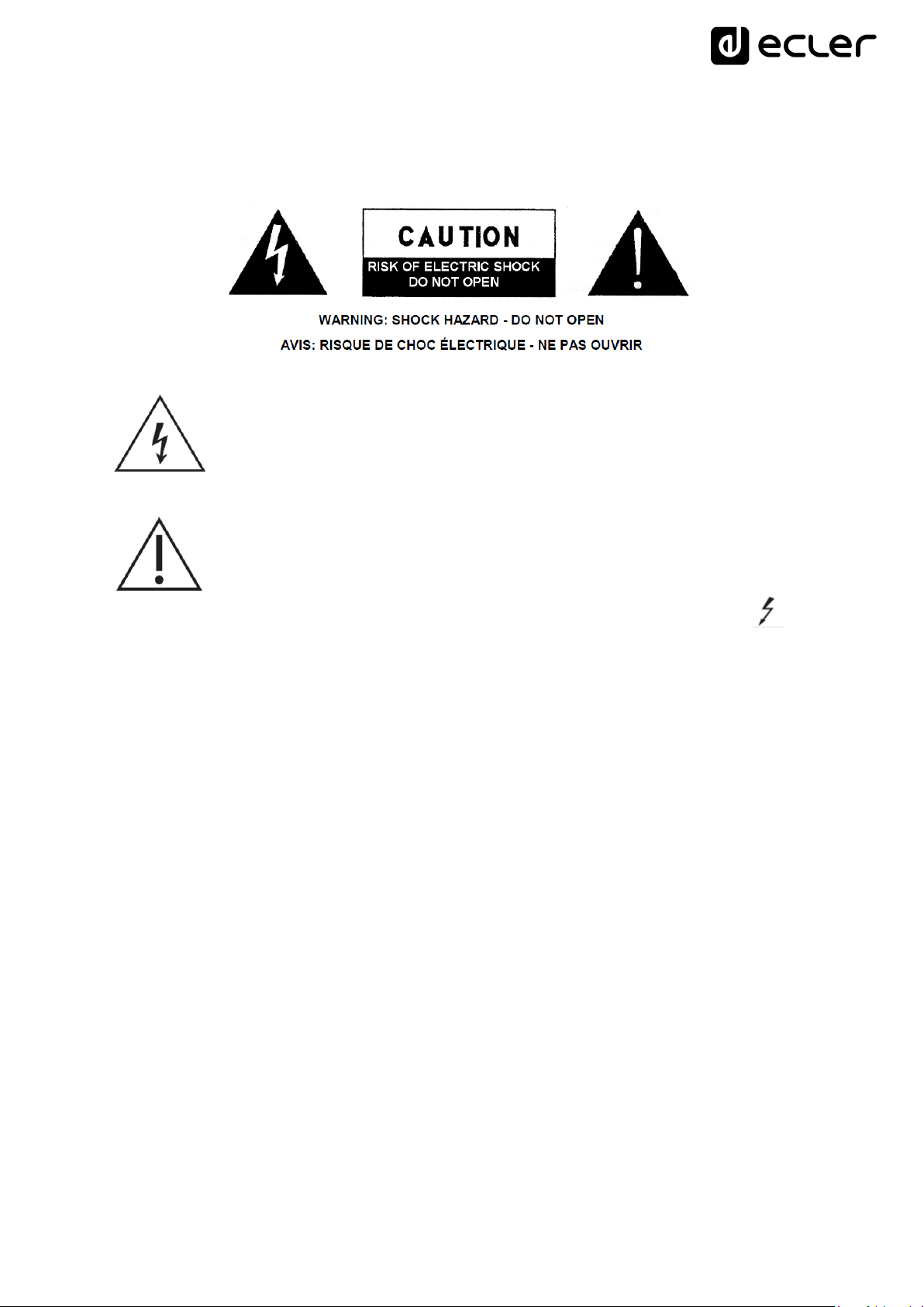
Once the unit is connected to the network, powered (via PoE or optional external power
supply) and correctly configured from the EclerNet Manager application, the main screen
will display an image similar to the following:
Main screen, example
Text fields S1 to S3 show the first three options that can be selected using keys K1 to
K3. Field S4 shows the text "NEXT", inviting you to press the K4 key to display more
options suitable for selection. The total number of selectable options is defined by
managing carousels of audio inputs (sound sources) or presets for each control panel,
using the EclerNet Manager application.
If there are 4 or fewer selectable options, the screen will show them directly in fields S1
to S4, without adding the "NEXT" function as an option associated with the K4 key.
In the example above, which uses a carousel of audio sources as selectable options, we
see the following information:
S1, option 1 (currently selected = shown in negative): MIMO4040DN audio input
labeled DUO-NET. Selectable (=actionable) by pressing the key K1
S2, option 2: MIMO4040DN audio input labeled FM TUNER. Selectable by
pressing the K2 key
S3, option 3: MIMO4040DN audio input labeled ePLAYER1. Selectable by
pressing the K3 key
S4, option 4: Move to the next screen of valid options by pressing the K4 key.
S5, Vu-meter showing the currently set volume of the audio signal the remote
panel is pointing at (this signal can be an output, an input, a matrix crossover
point, or sending the currently selected source to the destination output).
S6, value of the currently set volume of the audio signal to which the remote panel
is pointing, or the "MUTE" symbol if the audio signal is muted.
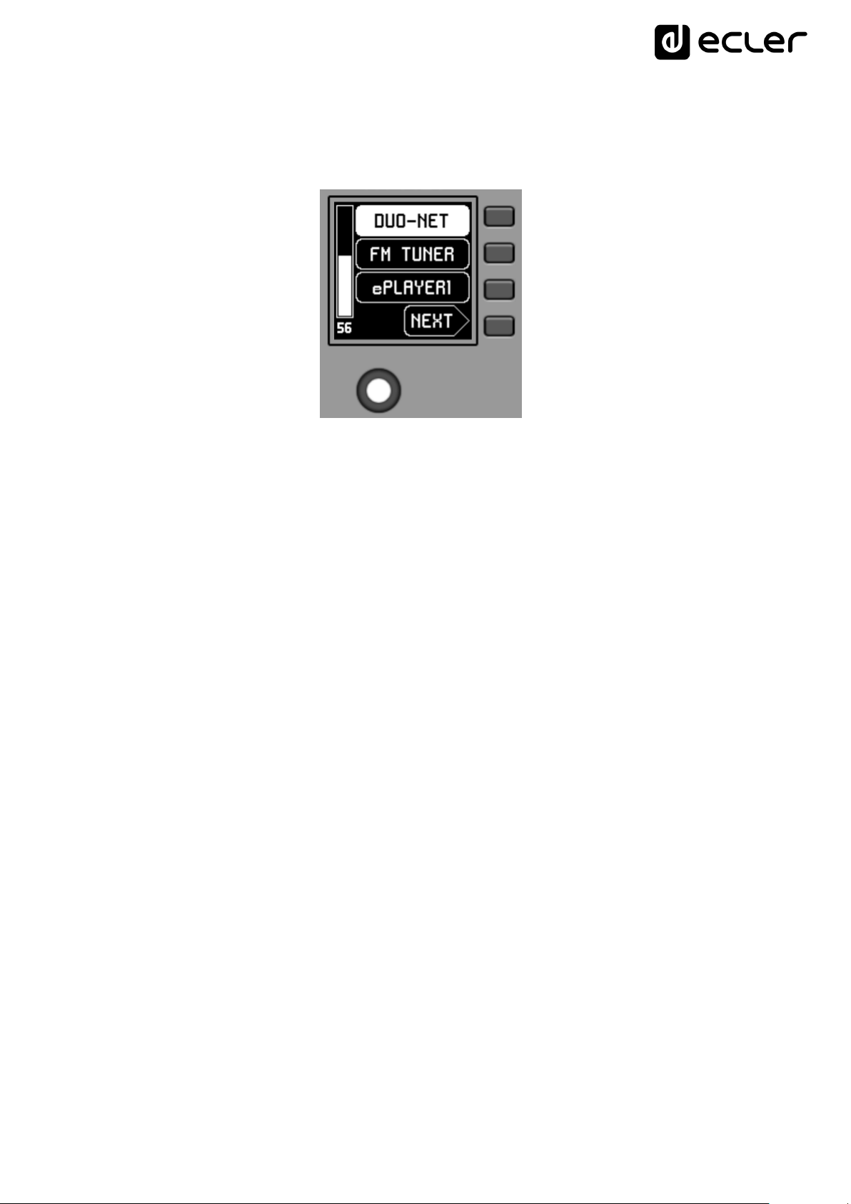
The following picture shows the selected FM TUNER input, and another volume
10
adjustment value in the Vu-meter, in this case the sending value of this input (sound
source) to the destination output (83).
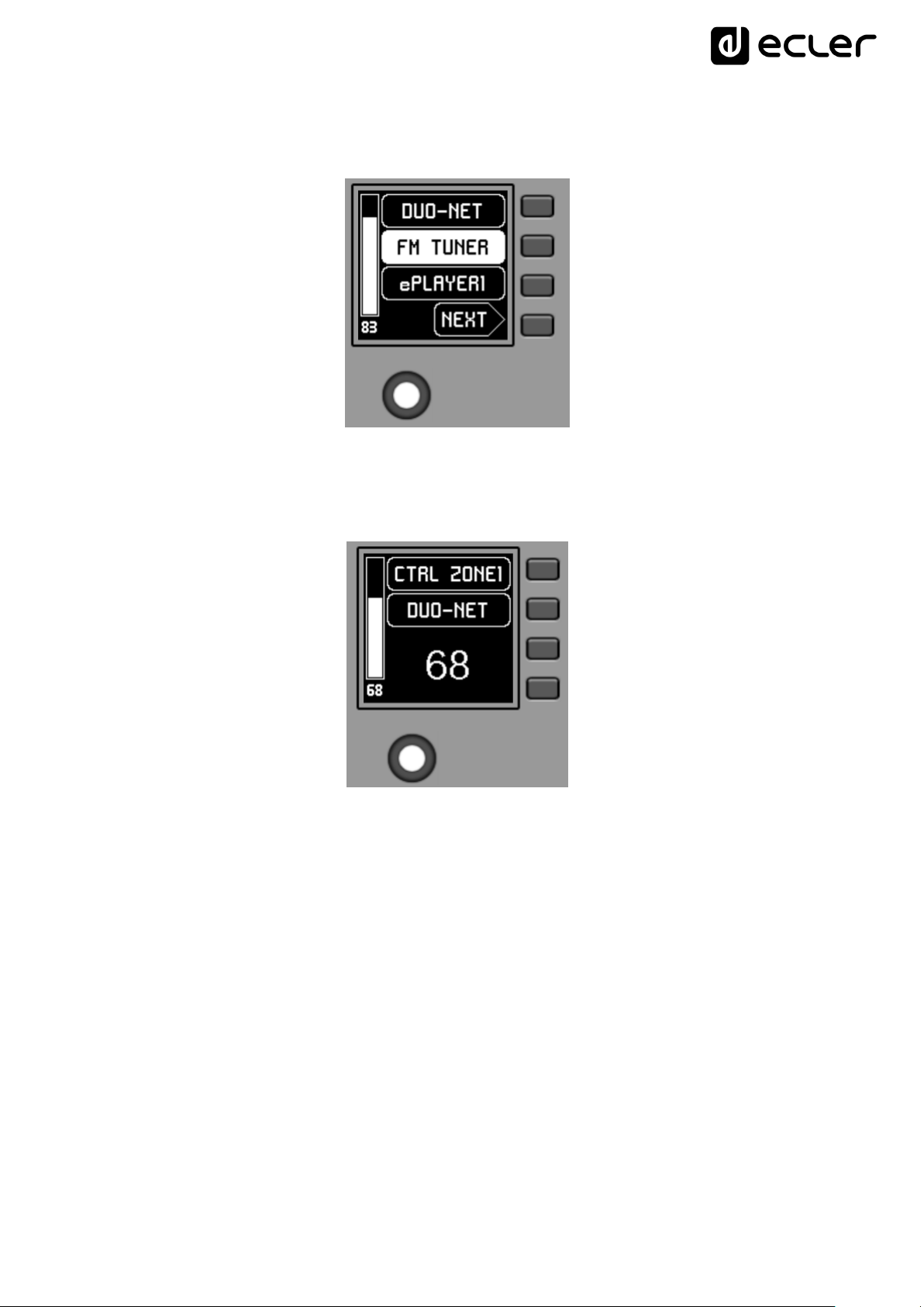
When acting on the K5 rotary control, aiming at modifying the volume to which it points,
a different screen is temporarily shown, returning a few seconds to the previous or main
screen. Example:
S1: Name (label) assigned to the control panel, defined from the EclerNet Manager
application. In the example "CTRL ZONE1".
S2: option of the currently selected carousel. In the "DUO-NET" example
S5, S6: volume value being adjusted by rotary control, displayed in real time, and
matching the same numerical value displayed in larger characters in the lower
middle section of the display (68 in the example above).
11
Pressing the rotary control activates the MUTE function, if enabled for triggering from
the WPNET4KV unit:
If the volume control function is not enabled for the WPNET4KV unit, turning or
pressing the rotary control will temporarily display such a screen, with the central
flashing “- -“ symbols:
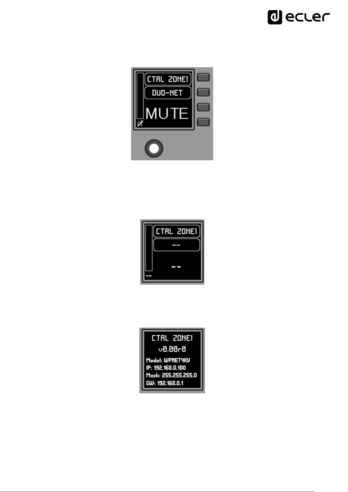
The long press (> 5 seconds) on the rotary control displays the configuration parameters
of the unit: name, model, firmware version and Ethernet network connection
parameters:
12
 Loading...