

Ecler NZA4-70, NZA4-180, NZA4-700, NZA6-70, NZA6-180 User Manual
...
USER MANUAL
MANUAL DE INSTRUCCIONES
NOTICE D'UTILISATION
BEDIENUNGSANLEITUNG


3
LIST OF CONTENTS
1. IMPORTANT NOTE 04
1.1. Precautions 04
2. INTRODUCTION 04
3. INSTALLATION 05
3.1. Location, assembly, ventilation 05
3.2. Mains connection 05
3.3. Signal input connections 05
3.4. Output connections 06
3.5. Ethernet port 06
3.6. Remote control ports for attenuation 06
3.7. REMOTE CONTROL ports connection 06
4. OPERATION AND USAGE 07
4.1. Start up 07
4.2. Front panel LED indicators 07
4.3. Front panel controls 08
5. CLEANING 08
6. FUNCTION LIST 09
7. FUNCTION DIAGRAM 09
8. TECHNICAL CHARACTERISTICS 31
9. BLOCK DIAGRAM 34
All numbers subject to variation due to production tolerances. ECLER S.A. reserves the right to make changes or
improvements in manufacturing or design which may affect specifications.

4
1. IMPORTANT NOTE
Congratulations! You are the owner of a carefully designed and manufactured equipment. We thank you
for trusting on us and choosing our NZA multichannel amplifier with Ethernet remote control.
In order to obtain maximum operativity and perfect functioning order, it is most important to carefully read
all considerations taken into account in this manual before connecting this amplifier.
We recommend our authorised Technical Services if any maintenance task should be needed so that
optimum operation shall be achieved.
NZA series amplifiers come with a 3-year warrantee.
1.1. Precautions
The amplifier should have an earth connection in good conditions (earth resistance, Rg=30 or less).
The environment must be dry and dustless. Do not expose the unit to rain or water splashes, and do not
place liquid containers or incandescent objects like candles on top of the unit. Do not obstruct the
ventilation grilles with any kind of material.
In case there is some type of intervention and/or connection-disconnection of the amplifier, it is most
important to previously disconnect the mains power supply.
Do not manipulate the output terminals to the loudspeakers when the amplifier is switched on, there are
voltages up to 400Vpp. The output cabling should be connected by a qualified technician. Otherwise only use premade flexible cables. There are no user serviceable parts inside the amplifier.
2. INTRODUCTION
The NZA series of multichannel amplifiers consists of 4 models with 4 channels and 2 with 6 channels:
NZA4-70: 4 x 80 W RMS
NZA4-180: 4 x 190 W RMS
NZA4-400: 4 x 420 W RMS
NZA4-700: 4 x 730 W RMS
NZA6-70: 6 x 80 W RMS
NZA6-180: 6 x 200 W RMS
All models are equipped with convection cooling, without fan, a feature allowing a very quiet operation,
suitable for installation in noise sensitive environments.
Channels can independently operate or can be linked, two operating modes being then available: BRIDGE
(one pair behaves as a single higher power amplifier) or PARALLEL (one pair has two amplified outputs, but both
receive and deliver identical signals, simultaneously managed).
In addition, it incorporates important technological innovations concerning digital processing and remote
management via Ethernet, turning it into the perfect candidate to address mobile applications and fixed
installations, both centralized and distributed, requiring high level remote control and monitoring and
integration with standard Ethernet networks. NZA amplifiers include as standard an EclerNet internal module
for DSP processing and remote management, allowing physical connection between the amplifier and an Ethernet
network as well as its remote management and supervision from any point of it, using Windows® EclerNet
Manager (*) software. Please refer to the EclerNet Manager software manual for more information.
Other features of this series are:
Volume remote control ports (1 per channel)
Soft Start function, except for 4-70 and 6-70 models
Integrated DSP processing (8-band parametric EQ, crossovers, delay, compressor, etc.) remotely
controllable via Ethernet (EclerNet Manager software (*))
Auto-Standby function (automatic sleep mode when there is no audio input signal)
Clipping prevention function ("anti-clip") with 3 levels of performance
Screw terminal block for connection
* EclerNet Manager software is available on www.ecler.com.
5
3. INSTALLATION
3.1. Location, assembly, ventilation
The NZA amplifiers are 2 RU high 19'' rack modules.
It is very important not to enclose the amplifier or expose it to extreme temperatures as it generates heat.
It’s also necessary to promote the passage of fresh air through the ventilation holes of the chassis, leaving
at least one rack unit (NZA4-700 (2)) off between each device and installed above and below it in the rack
frame.
If the setup has several amplifiers in the same rack or in a closed cabinet with doors, it is highly
recommended to supply them forced ventilation, installing fans at the upper and lower ends. This upward air flow
will help to dissipate the heat generated inside.
In order to optimize as much as possible the correct thermal dissipation of equipment installed in a closed
rack, it is advisable not to place power amplifiers under other appliances, but upon these ones.
All NZA amplifiers are supplied with plastic washers in order not to damage the rack ears when tightening
the screws.
3.2. Mains connection
The NZA amplifiers are fed with alternate currents, depending on the country, of 110-120, 220-240V
47/63Hz. (see characteristics in the back of the unit).
The mains cables must not be near the shielded cables carrying the audio signal, as this could cause
humming.
3.3. Signal input connections
NZA series rear panel provides analog, balanced, line level signal inputs. Selecting hardware inputs and
their routing to either amplifier channel is done from EclerNet Manager control application. Please refer to the
EclerNet Manager software manual for more information.
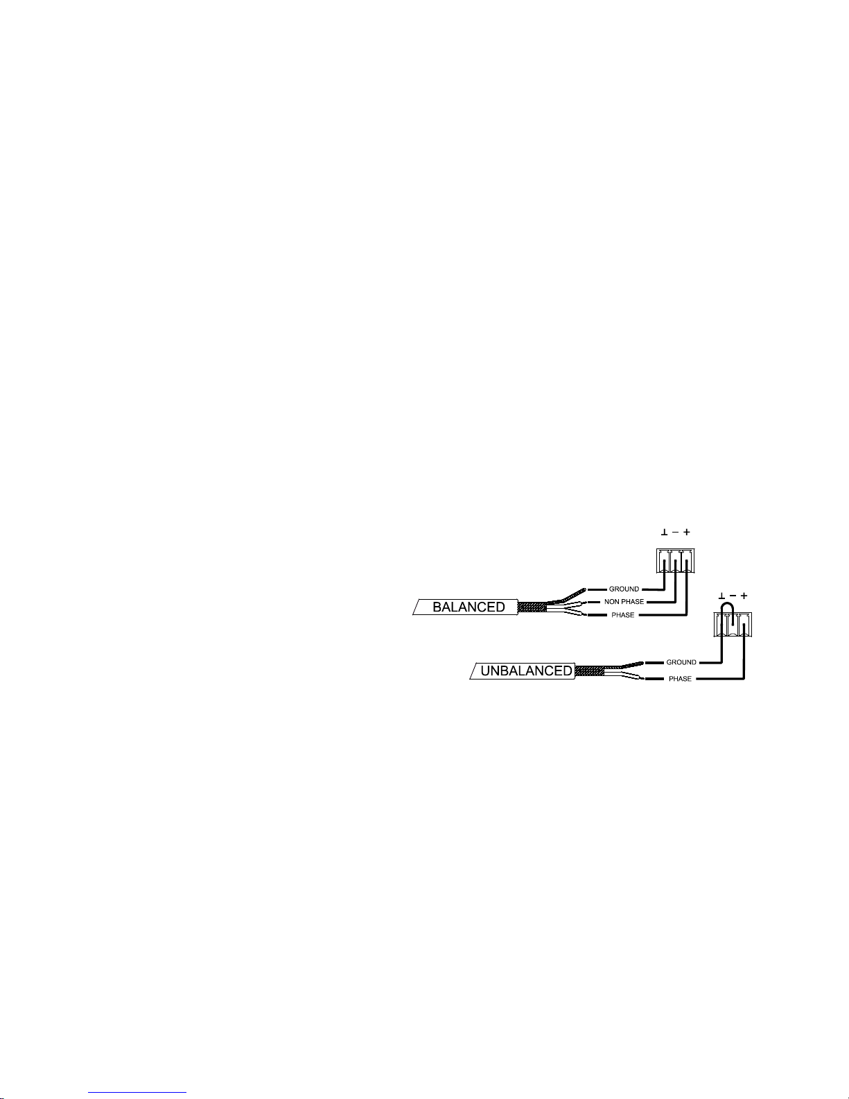
Signal input connectors are 3 position screw terminal block (7). The wiring is:
HOT or direct signal > Pin +
COLD or inverted signal > Pin GROUND > Pin
For unbalanced connection short-circuit pin
to pin -.
STACK outputs (8) available for inputs 1 and
2 are parallel to the input and serve to re-send the
signal of these inputs (INPUTS, CH1 / CH2) to other
input channels, amplifiers or sound systems.
The input impedance is 22K (balanced). This impedance makes possible to parallel several amplifiers
without loosing audio quality.
6
3.4. Output connections
The rear panel OUTPUTS section is fitted with two position screw terminal block (9) for each amplifier
channel (4 or 6, depending on model). Always respect the relative polarity for outputs (+ and - on each output
connector), wiring and speakers. In bridge mode, follow the wiring and polarity standard indicated near the output
screw terminal block and labeled as "BRIDGE".
SINGLE / PARALLEL / BRIDGE operating modes are selected from EclerNet Manager control application.
Please refer to the EclerNet Manager software manual for more information.
The connection cable that joins the amplifiers outputs and the loudspeakers must be of good quality,
sufficient section and as short as possible. This is most important when the distances to cover are long ones i.e. up
to 10 meters it is recommended to use a section not inferior to 2.5mm
2
and for superior distances 4mm2.
3.5. Ethernet port
An RJ-45 connector (10) allows connecting the equipment to an Ethernet network and its management
from EclerNet Manager software. Please refer to the EclerNet Manager software manual for more information.
3.6. Remote control ports for attenuation
NZA series rear panel provides 4 or 6 (depending on model) remote control ports (11) labeled as "REMOTE
CONTROL". With EclerNet Manager application, you can assign a port to one or more channels of the amplification
unit in order to remotely attenuate the input signal volume (and therefore the output volume of the affected channels)
remotely.
The maximum signal level in each amplification channel, and therefore its output volume (using or not remote
attenuation and outside DSP processing done from EclerNet Manager application) is determined by the position of
your front panel rotary control (1).
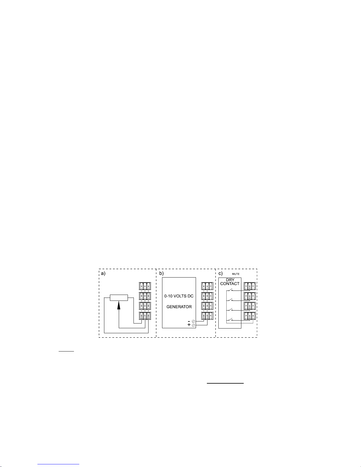
3.7. REMOTE CONTROL ports connection
The signal remote attenuation level for each input channel can be set by using 3 types of external devices
connected to the rear panel REMOTE CONTROL ports:
a) Using a remote potentiometer with nominal resistance between 10k and 50k.
b) Using a device that generates a control voltage from 0 to 10V DC.
c) Using remote relays/dry contacts.
NOTE
: you can connect up to 16 REMOTE CONTROL ports in parallel to the same hardware control
potentiometer. You have to merge the ground of all amplifiers belonging to these ports.
The connection cables can be up to 500m long if a section of 0.5mm
2
is used.
Consult the available accessories at your ECLER dealer or at www.ecler.com
.

7
4. OPERATION AND USAGE
4.1. Start up
When you operate the POWER switch (13) on the rear panel, the amplifier is supplied with power from the
electrical network and can be switched on, locally by holding down the front POWER key (6) or remotely (from the
application EclerNet Manager).
In a complete audio installation, it is important to start up the equipment in the following sequence: sound
sources, mixer, equalizers, active filters, processors and finally power amplifiers. To turn them off the sequence
should follow an inverse pattern.
4.2. Front panel LED indicators
NZA amplifiers are equipped with the following LEDs on their front panel:
SP indicators (2): They indicate the presence of a signal in the amplifier inputs. These indicators light up when
the signal present in the input exceeds the threshold of –40 dB.
CLIP / PROTECT indicators (4): (available only on models 4-180, 6-180, 4-400 and 4-700)
They light up for two possible reasons:
o When the signal delivered to the speaker is close to the actual clipping level. The CLIP detection
system considers possible voltage fluctuations of power supply, always giving a real indication
even if they exist. It is normal for CLIP indicators to be lit at the bass frequencies rhythm for high
operating levels, as these frequencies have the higher energy content. You must take care that
these indicators do not permanently light up during normal operation of the equipment.
o To indicate the absence of signal at the amplified output of the unit in the following cases:
During the startup process up to the end of the STANDBY time necessary to stabilize the
amplifier internal tensions, before being finally operational.
The equipment enters protection mode if it detects a low frequency signal that may
damage the speakers, excessive internal temperature, a short circuit at the amplified
output or a possible internal damage.
In any case, if these indicators permanently light up, it is a sign of malfunctioning and its
cause should be investigated.
CLIP indicators (3): (available only on models 4-70 and 6-70)
They light up when the signal delivered to the speakers is near clipping. The CLIP system considers
possible voltage fluctuations of power supply, always giving a real indication even if they exist. It is normal
for CLIP indicators to be lit at the bass frequencies rhythm for high operating levels, as these frequencies
have the higher energy content. You must take care that these indicators do not permanently light up
during normal operation of the equipment.
DATA transfer indicator (5): blinks to indicate data transfer activity between the amplifier and the remote
control PC running EclerNet Manager application.
Note: all front panel LEDs blink when the "Device Finder" function is activated in EclerNet Manager
application. That’s useful for identifying a physical device from its virtual counterpart in this application.
Please refer to the EclerNet Manager software manual for more information.

8
4.3. Front panel controls
The front panel includes a series of knobs and a on/off button.
The equipment can be locally switched on by holding down the POWER key until the startup sequence
begins. Shutdown also requires holding down the same key during a brief period.
The POWER key has an integrated LED that lights up in orange when the amplifier is in standby mode
(STANDBY), in green during operation (ON), and in red during the startup sequence or when the amplifier is in
protection mode.
Once the amplifier is turned on and the startup is complete, the unit is available for normal operation.
The front panel knobs (one per channel) allow to independently adjust the maximum output volume of each
amplifier channel. Moreover, EclerNet Manager application allows the DSP processing management (volume,
phase, equalization, compression, delays, etc.) of each channel independently (SINGLE mode) or by pairs
(BRIDGE & PARALLEL modes) and the Ethernet remote management, individually or by groups of channels and /
or amplifiers. Please refer to the EclerNet Manager software manual for more information.
Note: NZA amplifiers are setup with the following factory default parameters:
Channels in SINGLE mode
Inputs directly linked to the outputs (1 to 1, 2 to 2, etc.).
Channel gain selector: 26 dB
Channel Volume: 0 dB
Crossover filters, EQ, compressor and delay deactivated (off)
In this way, it’s possible to directly use the amp (without DSP processing or adjustments made through
EclerNet Manager) as a classic multichannel amplifier.
In PARALLEL & BRIDGE modes, the maximum output level for each pair of channels can only be set from
the first of the two knobs of each pair (CHANNEL 1 for the 1 & 2 pair, Channel 3 for the 3 & 4 pair and Channel 5
for the 5 & 6 pair).
Remote control ports also allow the volume adjustment of each amplifier channel (or pair of channels) from
a potentiometer or another external hardware device, the maximum volume being determined by the position of the
front rotary control for each channel.
In the device packaging, you’ll find a bag with clear caps to be inserted on the front panel knobs. They
protect the input attenuation settings from unsolicited tampering. Once inserted, you must use a flathead
screwdriver or a similar tool to remove them.
5. CLEANING
The front panel should not be cleaned with dissolvent or abrasive substances because silk-printing could
be damaged. To clean it, use a soft cloth slightly wet with water and neutral liquid soap; dry it with a clean cloth. Be
careful that water never gets into the amplifier through the holes of the front panel.
9
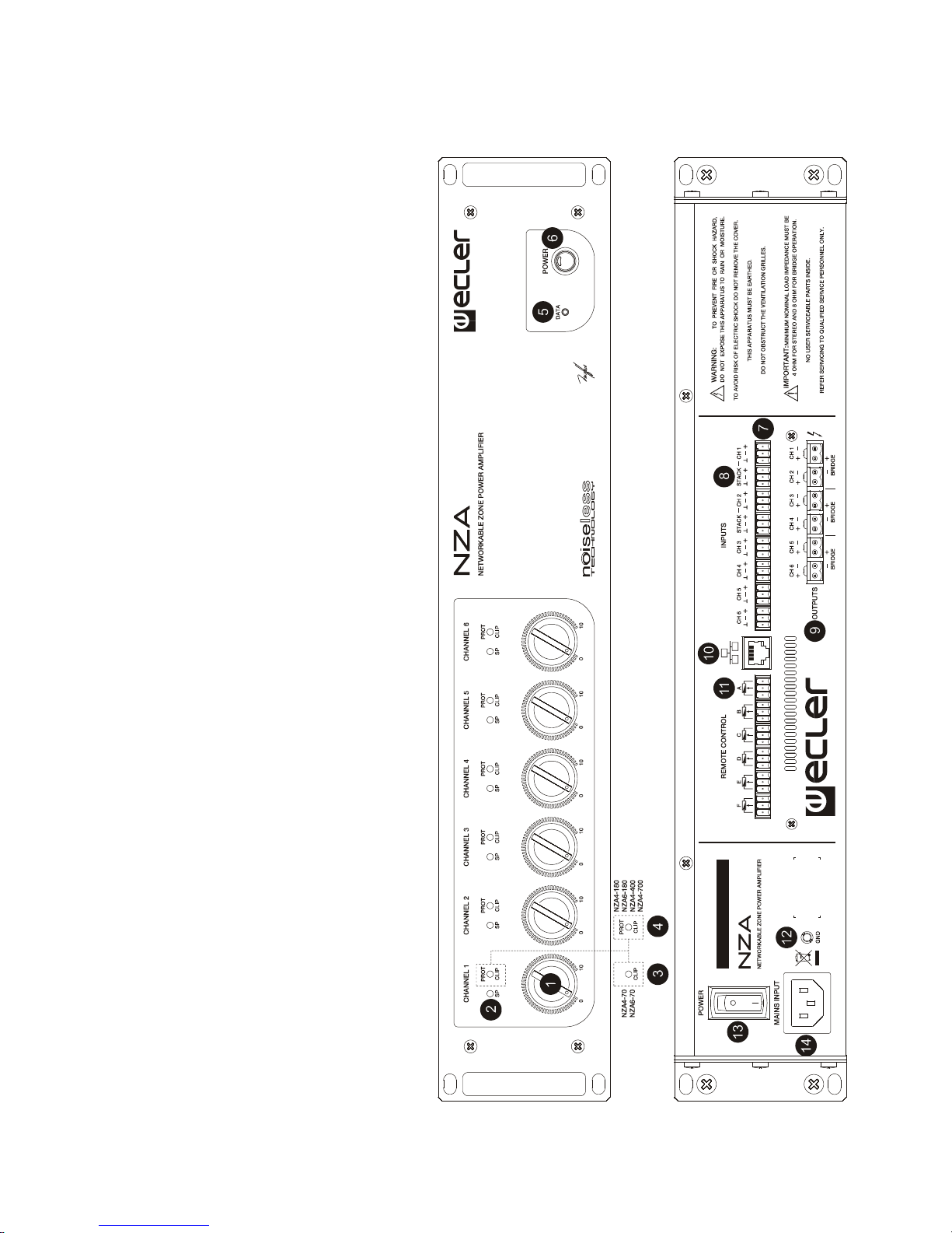
6. FUNCTION LIST 7. FUNCTION DIAGRAM
1. Input attenuator
2. Signal present indicator, SP
3. Clip indicator, CLIP
4. Combined clip and protection indicator,
CLIP/PROT
5. Data transfer indicator, DATA
6. On / Off key, POWER ON
7. Input terminal block
8. Terminal block to other amplifiers, STACK
9. Output terminal block
10. Ethernet port
11. Terminal block for remote control
12. Earth terminal, GND
13. Start-up switch
14. Mains socket

10
ÍNDICE
1. NOTA IMPORTANTE 11
1.1. Precauciones 11
2. INTRODUCCIÓN 11
3. INSTALACIÓN 12
3.1. Ubicación, montaje, ventilación 12
3.2. Conexión a red eléctrica 12
3.3. Conexiones de entrada de señal 12
3.4. Conexiones de salida 13
3.5. Puerto Ethernet 13
3.6. Puertos de control remoto de atenuación 13
3.7. Conexionado de los puertos REMOTE CONTROL 13
4. FUNCIONAMIENTO 14
4.1. Puesta en marcha 14
4.2. Indicadores LED del panel frontal 14
4.3. Controles del panel frontal 15
5. LIMPIEZA 15
6. LISTA DE FUNCIONES 16
7. DIAGRAMA DE FUNCIONAMIENTO 16
8. CARACTERÍSTICAS TÉCNICAS 31
9. DIAGRAMA DE BLOQUES 34
Todos los datos están sujetos a variación debida a tolerancias de producción. ECLER S.A. se reserva el derecho de realizar
cambios o mejoras en la fabricación o diseño que pudieran afectar las especificaciones.

11
1. NOTA IMPORTANTE
¡Enhorabuena!. Vd. posee el resultado de un cuidadoso diseño y una esmerada fabricación. Agradecemos
su confianza por haber elegido nuestro amplificador multicanal serie NZA con control remoto Ethernet.
Para que pueda conseguir la máxima operatividad y un funcionamiento perfecto, antes de su conexión es
MUY IMPORTANTE que lea detenidamente las consideraciones que se detallan en éste manual.
Para asegurar el óptimo rendimiento del aparato, su mantenimiento debe ser realizado por nuestros
Servicios Técnicos.
La serie de amplificadores NZA tiene una garantía de 3 años.
1.1. Precauciones
La etapa debe conectarse a una toma de tierra en correctas condiciones (Resistencia de tierra, Rg =
30 o menos). El ambiente de trabajo deberá ser seco y estar totalmente libre de polvo. No exponga el
aparato a la caída de agua o salpicaduras, no ponga encima objetos con líquido ni fuentes de llama
desnuda, como velas. No obstruya los orificios de ventilación con ningún tipo de material. En caso de
requerir alguna intervención y/o conexión-desconexión del amplificador debe desconectarse previamente la
alimentación.
No manipular los terminales de salida hacia el altavoz con la etapa en marcha; se hallan presentes
tensiones de hasta 400 Vpp. El cableado de la salida debe ser realizado por personal técnico cualificado o usar
cables flexibles ya preparados. En el interior del amplificador no existen elementos manipulables por el usuario.
2. INTRODUCCIÓN
La serie NZA de amplificadores multicanal consta de 4 modelos de 4 canales y otros 2 de 6 canales:
NZA4-70: 4 x 80 W RMS
NZA4-180: 4 x 190 W RMS
NZA4-400: 4 x 420 W RMS
NZA4-700: 4 x 730 W RMS
NZA6-70: 6 x 80 W RMS
NZA6-180: 6 x 200 W RMS
Todos los modelos disponen de ventilación por convección, sin ventilador, característica que les confiere
un funcionamiento muy silencioso y apto para su instalación en entornos sensibles al ruido ambiental.
Los canales pueden trabajar de manera independiente o bien emparejados, siendo posible en éste último
caso los modos de trabajo PUENTE (una pareja se comporta como un único amplificador de mayor potencia) o
PARALELO (una pareja mantiene sus dos salidas amplificadas, pero ambas reciben y entregan señales idénticas,
siendo gobernadas de manera simultánea).
Incorpora además importantes innovaciones tecnológicas en cuanto a procesamiento digital y gestión
remota vía Ethernet, que la convierten en el perfecto candidato para acometer aplicaciones móviles e
instalaciones fijas, tanto centralizadas como distribuidas, que requieran de control y supervisión remotos de
alto nivel e integración con redes Ethernet estándar. Los amplificadores NZA incluyen de serie un módulo
interno de procesamiento DSP y gestión remota EclerNet, que permiten el conexionado físico del amplificador a
una red Ethernet y su gestión y supervisión remotas desde cualquier punto de la misma, empleando para ello la
aplicación Windows® EclerNet Manager (*). Consulte el manual de la Aplicación EclerNet Manager para obtener
más información.
Otras características destacables de esta serie son:
Puertos de control remoto de volumen (1 por canal)
Función de arranque suave (Soft Start), excepto en los modelos 4-70 y 6-70
Procesamiento DSP integrado (EQ paramétrica de 8 cortes, crossovers, Delay, Compresor, etc.) y
gestionable remotamente vía Ethernet (software EclerNet Manager (*))
Función Auto-Standby (modo de reposo automático en ausencia de señal de audio en las
entradas)
Función de prevención de recortes (“anti-clip”) con 3 niveles de actuación
Conexionado con regletas de tornillos
* La aplicación EclerNet Manager se encuentra disponible en www.ecler.com.
 Loading...