

Page 1

WHEELED
VACUUM
WV190 - B&S 190cc PUSH
WV190S - B&S 190cc SELF
ENGLISH ESPAÑOL FRANÇAIS
PROPELLED
WV179 - KAWASAKI 179cc PUSH
WV179S - KAWASAKI 179cc SELF PRO-
PELLED
SN Range: 900890 - A01242
OWNER'S MANUAL
PN: 13887-00
Rev. 022409
Companion to 13888-00
Page 2

Before You Begin
MANUFACTURED BY CRARY INDUSTRIES
MANUFACTURED IN U.S.A.
XXXXXX
WEST FARGO, NORTH DAKOTA 58078 U.S.A.
SERIAL NUMBER
DEAR ECHO BEAR CAT CUSTOMER
Thank you for purchasing a ECHO Bear Cat product. The ECHO Bear Cat line is designed, tested, and manufactured
to give years of dependable performance. To keep your machine operating at peak efciency, it is necessary to adjust
it correctly and make regular inspections. The following pages will assist you in the operation and maintenance of your
machine. Please read and understand this manual before operating your machine.
If you have any questions or comments about this manual, please call us toll-free at 1-800-247-7335.
If you have any questions or problems with your machine, please call or write your local authorized ECHO Bear Cat Dealer.
This document is based on information available at the time of its publication. ECHO Bear Cat is continually making
improvements and developing new equipment. In doing so, we reserve the right to make changes or add improvements
to our product without obligation for equipment previously sold.
PLEASE SEND US YOUR WARRANTY CARD
A warranty card is included in your owner's kit packaged with your machine. Please take the time to ll in the information
requested on the card. When you send your completed card to us, we will register your machine and start your coverage
under our limited warranty.
FOR MACHINE SERVICE OR PARTS:
For service assistance, contact your nearest authorized
ECHO Bear Cat dealer or the factory. For parts, contact
your authorized dealer. The parts manual for your machine
is available at http://bearcatproducts.com/main/support/
index_html. Your dealer will need to know the serial number
of your machine to provide the most efcient service. See
below for information on how to identify and record the serial
number for your machine.
FOR ENGINE SERVICE OR PARTS:
For engine service or parts, contact your nearest authorized
engine dealer. ECHO Bear Cat does not handle any parts,
repairs or warranties for engines.
SERIAL NUMBER LOCATION
Please record the serial number in the space provided and
on the warranty and registration card.
ORDERING PARTS
Only genuine ECHO Bear Cat replacement parts should
be used to repair the machine. Replacement parts
manufactured by others could present safety hazards, even
though they may t on this machine. Replacement parts
are available from your ECHO Bear Cat dealer.
Provide the following when ordering parts:
The SERIAL NUMBER of your machine.
The PART NUMBER of the part.
The PART DESCRIPTION.
The QUANTITY needed.
SERIAL NUMBER
HOW TO CONTACT ECHO BEAR CAT
ADDRESS PHONE E-MAIL HOURS
237 NW 12th Street
P.O. Box 849
West Fargo, ND 58078
*Original Instructions
© 2009, CRARY INDUSTRIES, ALL RIGHTS RESERVED. PRODUCED AND PRINTED IN THE U.S.A.
800-247-7335
701-282-5520
FAX: 701-282-9522
opesales@crary.com
service@crary.com
Monday - Friday,
8 am to 5 pm
Central Time
Page 3

LIMITED WARRANTY
This warranty applies to all AG and Outdoor Power Equipment manufactured by Crary Industries.
Crary Industries warrants to the original owner each new Crary Industries product to be free from defects
in material and workmanship, under normal use and service. The warranty shall extend 1 year from date of
delivery for income producing (commercial) applications and 2 years from date of delivery for non-income
producing (consumer) use of the product. The product is warranted to the original owner as evidenced by a
completed warranty registration on file at Crary Industries. Replacement parts are warranted for (90) days
from date of installation.
THE WARRANTY REGISTRATION MUST BE COMPLETED AND RETURNED TO CRARY INDUSTRIES
WITHIN 10 DAYS OF DELIVERY OF THE PRODUCT TO THE ORIGINAL OWNER OR THE WARRANTY
WILL BE VOID.
In the event of a failure, return the product, at your cost, along with proof of purchase to the selling Crary
Industries dealer. Crary Industries will, at its option, repair or replace any parts found to be defective in material
or workmanship. Warranty on any repairs will not extend beyond the product warranty. Repair or attempted
repair by anyone other than a Crary Industries dealer as well as subsequent failure or damage that may occur
as a result of that work will not be paid under this warranty. Crary Industries does not warrant replacement
components not manufactured or sold by Crary Industries.
This warranty applies only to parts or components that are defective in material or workmanship. 1.
This warranty does not cover normal wear items including but not limited to bearings, belts, pulleys, filters 2.
and chipper knives.
This warranty does not cover normal maintenance, service or adjustments.3.
This warranty does not cover depreciation or damage due to misuse, negligence, accident or improper 4.
maintenance.
ENGLISH
This warranty does not cover damage due to improper setup, installation or adjustment.5.
This warranty does not cover damage due to unauthorized modifications of the product. 6.
Engines are warranted by the respective engine manufacturer and are not covered by this warranty.7.
Crary Industries is not liable for any property damage, personal injury or death resulting from the unauthorized
modification or alteration of a Crary product or from the owner’s failure to assemble, install, maintain or operate
the product in accordance with the provisions of the Owner’s manual.
Crary Industries is not liable for indirect, incidental or consequential damages or injuries including but not
limited to loss of crops, loss of profits, rental of substitute equipment or other commercial loss.
This warranty gives you specific legal rights. You may have other rights that may vary from area to area.
Crary Industries makes no warranties, representations or promises, expressed or implied as to the performance
of its products other than those set forth in this warranty. Neither the dealer nor any other person has any
authority to make any representations, warranties or promises on behalf of Crary Industries or to modify the
terms or limitations of this warranty in any way. Crary Industries, at its discretion, may periodically offer limited,
written enhancements to this warranty.
CRARY INDUSTRIES RESERVES THE RIGHT TO CHANGE THE DESIGN AND/OR SPECIFICATIONS
OF ITS PRODUCTS AT ANY TIME WITHOUT OBLIGATION TO PREVIOUS PURCHASERS OF ITS
PRODUCTS.
Page 4

TABLE OF CONTENTS
DESCRIPTION PAGE
SAFETY ..............................................................................................................1
1.1 SAFETY ALERT SYMBOL ....................................................................................1
1.2 EMISSION INFORMATION ...................................................................................1
1.3 BEFORE OPERATING ..........................................................................................2
1.4 OPERATION SAFETY ..........................................................................................2
1.5 MAINTENANCE/STORAGE SAFETY ...................................................................2
1.6 SAFETY DECALS .................................................................................................3
ASSEMBLY ......................................................................................................... 4
2.1 INSTALLING THE HANDLEBAR ..........................................................................5
2.2 INSTALLING THE BAG .........................................................................................5
2.3 CHECKING/ADDING MOTOR OIL .......................................................................5
2.4 FILLING THE TANK ..............................................................................................5
FEATURES & CONTROLS .................................................................................6
3.1 VACUUM COMPONENTS .....................................................................................6
3.2 VACUUM CONTROLS ...........................................................................................7
OPERATION .......................................................................................................8
4.1 STARTING THE VACUUM ....................................................................................8
4.2 STOPPING THE VACUUM ...................................................................................8
4.3 VACUUMING .........................................................................................................9
4.4 ADJUSTING HANDLEBAR HEIGHT ......................................................................9
4.5 ADJUSTING NOZZLE HEIGHT ..........................................................................10
4.6 ATTACHING/EMPTYING THE BAG ....................................................................10
SERVICE & MAINTENANCE ............................................................................ 11
5.1 MAINTENANCE SCHEDULE..............................................................................11
5.2 DEBRIS BAG BREAK-IN ....................................................................................12
5.3 ADJUSTING THE BELT ......................................................................................12
5.4 CLEARING A PLUGGED ROTOR ......................................................................12
TROUBLESHOOTING ...................................................................................... 13
SPECIFICATIONS ............................................................................................. 14
7.1 GENERAL SPECIFICATIONS..............................................................................14
7.2 BOLT TORQUE ...................................................................................................15
Page 5
1
Section
SAFETY
1.1 SAFETY ALERT SYMBOL
The Owner/Operator's manual uses this symbol to alert
you of potential hazards. Whenever you see this symbol,
read and obey the safety message that follows it. Failure
to obey the safety message could result in personal injury,
death or property damage.
CAUTION
Indicates a potentially hazardous situation that, if not
avoided, may result in minor or moderate injury.
WARNING
Indicates a potentially hazardous situation that, if not
avoided, could result in death or serious injury.
DANGER
1.2 EMISSION INFORMATION
Under California Law and the
laws of several other states, you
are not permitted to operate an
internal combustion engine using
hydrocarbon fuels on any forest
covered, brush covered or grass
covered land or on land covered
with grain, hay or other ammable agricultural crops,
without an engine spark arrester in continuous effective
working order.
The engine on your power equipment, like most outdoor
power equipment, is an internal combustion engine that
burns gasoline or diesel fuel (hydrocarbons). Therefore,
your power equipment must be equipped with a spark
arrester mufer in continuous effective working order. The
spark arrester must be attached to the engine exhaust
system in such a manner that ames or heat from the
system will not ignite ammable material.
Failure of the owner/operator of the equipment to comply
with this regulation is a misdemeanor under California law
and may also be a violation of other state and/or federal
regulations, laws, ordinances, or codes. Contact your local
re marshal or forest service for specic information about
which regulations apply in your area.
The standard muffler installed on the engine is not
equipped with a spark arrester. One must be added before
using this machine in an area where a spark arrester is
required by law. Contact the local authorities if these laws
apply to you. See your authorized engine dealer for spark
arrester options.
ENGLISH
Indicates an imminently hazardous situation that, if not
avoided, will result in death or serious injury.
WHEELED VACUUM
1
Page 6
SAFETY
1.3 BEFORE OPERATING
Read and understand this owner’s manual. Be 1.
completely familiar with the controls and the proper
use of this equipment.
Familiarize yourself with all of the safety and operating 2.
decals on this equipment and on any of its attachments
or accessories.
Keep safety decals clean and legible. Replace missing 3.
or illegible safety decals.
Obtain and wear safety glasses 4.
and use hearing protection at
all times when operating this
machine.
Av oid wear ing loo se fitt ed 5.
clothing. Never operate this
machine while wearing clothing
with drawstrings that could wrap around or get caught
in the machine.
Do not operate this machine if you are under the 6.
influence of alcohol, medications, or substances that
can affect your vision, balance or judgement. Do not
operate if tired or ill. You must be in good health to
operate this machine safely.
Do not operate this equipment in the vicinity of 7.
bystanders. Keep the area of operation clear of all
persons, particularly small children. It is recommended
that bystanders keep at least 50 feet (15 meters) away
from the area of operation.
Do not allow children to operate this equipment.8.
Use only in daylight or good artificial light.9.
Do not run this equipment in an enclosed area. Engine 10.
exhaust contains carbon monoxide gas, a deadly
poison that is odorless, colorless and tasteless. Do not
operate this equipment in or near buildings, windows
or air conditioners.
Always use an approved fuel container. Do not remove 11.
gas cap or add fuel when engine is running. Add fuel
to a cool engine only.
Do not fill fuel tank indoors. Keep open flames, sparks, 12.
smoking materials and other sources of combustion
away from fuel.
Do not operate machine without shields in place. 13.
Failure to do so may cause serious injury or death.
Keep all guards, deflectors, and shields in good 14.
working condition.
Before inspecting or servicing any part of this machine, 15.
shut off the machine and make sure all moving parts
have come to a complete stop. Disconnect the battery
and remove the ignition key where applicable.
Check that all screws, nuts, bolts, and other fasteners 16.
are secured, tightened and in proper working condition
before starting the machine.
Do not transport or move machine while it is operating 17.
or running.
1.4 OPERATION SAFETY
Set up your work site so you are not endangering traffic 1.
and the public. Take great care to provide adequate
warnings.
Kee p th e machin e clear of debr is and other 2.
accumulations.
Do not allow processed material to build up in the 3.
discharge area. This may prevent proper discharge
and can result in kickback of material through the feed
opening.
If the machine becomes clogged, or the machine 4.
starts vibrating or making an unusual noise, shut off
machine immediately and make sure all moving parts
have come to a complete stop. Disconnect the battery
and remove the ignition key if applicable. After the
machine stops: A) Inspect for damage, B) Replace
or repair any damaged parts, and C) Check for and
tighten any loose parts.
Do not tamper with the engine governor settings on 5.
the machine. The governor controls the maximum safe
operating speed and protects the engine and all moving
parts from damage cause by excessive speed.
1.5 MAINTENANCE/STORAGE SAFETY
Before inspecting, servicing, storing, or changing 1.
an accessory, shut off the machine and make sure
all moving parts have come to a complete stop.
Disconnect the battery and remove the ignition key
where applicable.
Replace any missing or unreadable safety decals. 2.
Refer to the safety decal section for part numbers.
Allow machine to cool before storing in an enclosure.3.
Store the machine out of reach of children and where 4.
fuel vapors will not reach an open flame or spark.
Never store this machine with fuel in the fuel tank 5.
inside a building where fumes may be ignited by an
open flame or spark. Ignition sources can be hot water
and space heaters, furnaces, clothes dryers, stoves,
electric motors, etc.
Drain the fuel and dispose of it in a safe manner for 6.
storage periods of three months or more.
2
WHEELED VACUUM
Page 7
SAFETY
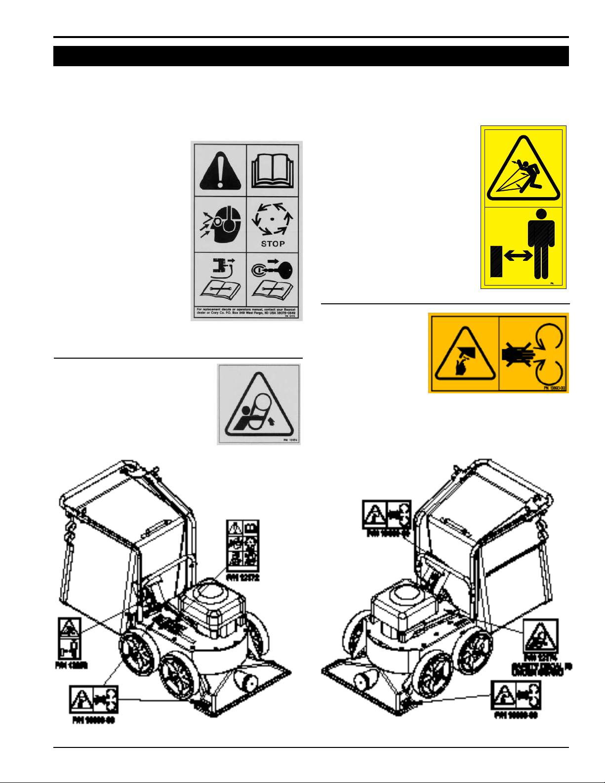
1.6 SAFETY DECALS
Familiarize yourself with all of the safety and operating decals on the machine and the associated hazards. See the
engine owner’s manual or contact the engine manufacturer for engine safety instructions and decals. Make certain that
all safety and operational decals on this machine are kept clean and in good condition. Decals that need replacement
must be applied to their original locations.
PN 12172
READ AND UNDERSTAND
THIS OWNER/OPERATORS
MANUAL. BE COMPLETELY
FAMILIAR WITH THE
CONTROLS AND THE PROPER
USE OF THIS EQUIPMENT.
OBTAIN AND WEAR SAFETY
GLASSES AND USE HEARING
PROTECTION AT ALL TIMES
WHEN OPERATING THIS
MACHINE.
BEFORE INSPECTING OR
SERVICING ANY PART OF THIS
MACHINE, SHUT OFF POWER
SOURCE, DISCONNECT
SPARK PLUG WIRE FROM
SPARK PLUG AND MAKE SURE ALL MOVING PARTS HAVE
COME TO A COMPLETE STOP.
PN 12174
DO NOT OPERATE MACHINE
WITHOUT SHIELDS IN PLACE.
FAILURE TO DO SO MAY CAUSE
SERIOUS INJURY OR DEATH.
PN 12252
DO NOT OPERATE THIS
EQUIPMENT IN THE VICINITY OF
BYSTANDERS. DO NOT ALLOW
CHILDREN TO OPERATE THIS
EQUIPMENT. ALWAYS STAND
CLEAR OF DISCHARGE AREA
WHEN OPERATING THIS MACHINE.
KEEP FACE AND BODY AWAY FROM
DISCHARGE AREAS.
PN 13890-00
KEEP HANDS AND FEET
OUT OF INLET AND
DISCHARGE OPENINGS
WHILE MACHINE IS
OPERATING TO AVOID
SERIOUS PERSONAL
INJURY. STOP AND
ALLOW MACHINE TO COME TO A COMPLETE STOP BEFORE
CLEARING OBSTRUCTIONS.
ENGLISH
WHEELED VACUUM
3
Page 8
2
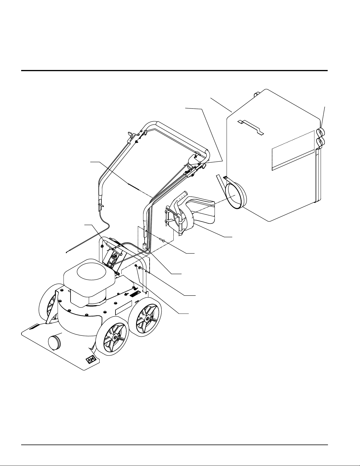
5/16" X 1-3/4"
CARRIAGE BOLT
5/16" FLAT
WASHER
5/16" NYLOCK NUT
7/8” PLASTIC CAP
BAG HANDLE W/ DEFLECTOR
VACUUM BAG
CABLE TIE
BAG HANGER BRACKETS
RAISE EXHAUST
DOOR TO ATTACH
BAG HANDLE
BAG LOOPS
Section
ASSEMBLY
Figure 2.1, Installing the upper handlebar and bag
4
WHEELED VACUUM
Page 9
ASSEMBLY
2.1 INSTALLING THE HANDLEBAR
Remove the two 7/8" plastic caps on the ends of the 1.
Vacuum upper handlebar.
Position the upper handlebar over the lower handlebar 2.
as shown in Figure 2.1. Install using 5/16" x 1-3/4"
carriage bolts, flat washers and nylock nuts.
Tighten 5/16" hardware to 17 ft-lbs.3.
Using the cable ties from the owner's kit, secure the 4.
control cables to the machine.
See Section 4.4 for handlebar height adjustment.5.
2.2 INSTALLING THE BAG
Install the Vacuum bag on the bag handle (Figure 1.
1). Tighten the bag over the handle using the bag
buckle.
Place the loops of the Vacuum bag into the bag hanger 2.
brackets.
Lift the exhaust door.3.
Attach the bag handle to the vacuum discharge.4.
2.3 CHECKING/ADDING MOTOR OIL
Check the oil level. If needed, fill the engine with the
type and amount of oil specified in the engine owner's
manual.
2.4 FILLING THE TANK
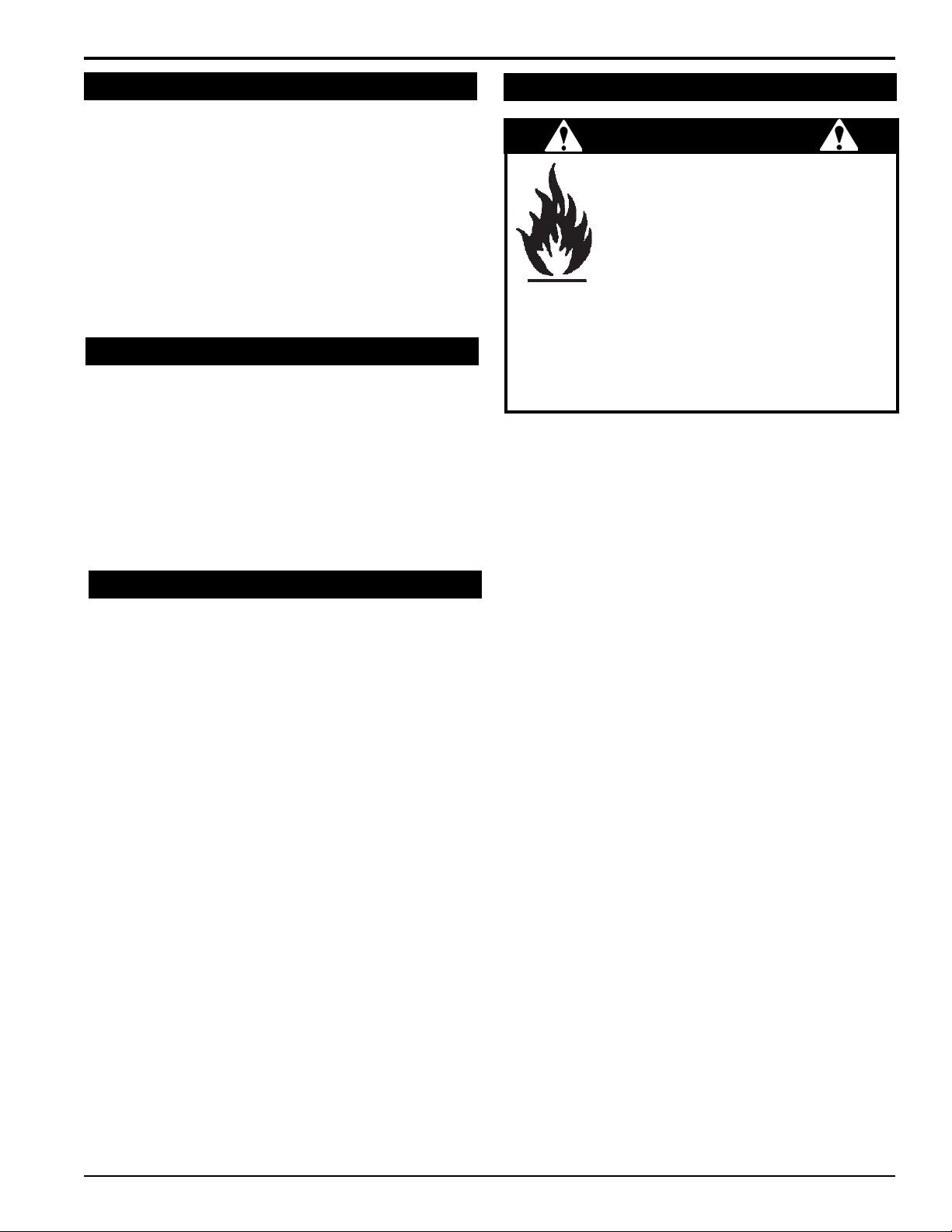
WARNING
Gasoline and diesel fuels are highly
ammable and their vapors are explosive.
To prevent personal injury or property
damage:
Store fuel only in approved containers,
in well ventilated, unoccupied buildings,
away from sparks or ames. A container
with a capacity of 2 gallons or less with a pouring spout
is recommended. Do not ll the fuel tank while the engine
is hot or running, since spilled fuel could ignite if it comes
in contact with hot parts or sparks from ignition. Do not
start the engine near spilled fuel. Never use fuel as a
cleaning agent. DO NOT MIX OIL WITH FUEL.
Use only those types of fuels that are recommended in
your engine owner’s manual.
To add fuel:
Stop engine, wait for all parts to stop moving and 1.
disconnect spark plug wire. Remove key from key
switch. Allow the engine and muffler to cool for at
least three minutes.
Clean area around fuel fill cap and remove cap.2.
Using a clean funnel, fill fuel tank to 1/2” below bottom 3.
of filler neck to provide space for any fuel expansion.
Install fuel fill cap securely and wipe up any spilled
gasoline.
ENGLISH
WHEELED VACUUM
5
Page 10

BAG HANDLE / DEFLECTOR
COLLECTION BAG
THROTTLE ASSEMBLY
CLUTCH CONTROL BAIL
HEIGHT ADJUSTMENT
GEAR SHIFT CONTROL
EXHAUST DOOR
FAN INTAKE HOUSING
TRANSMISSION
INTAKE FOR OPTIONAL
VENTILATION OPENING
FAN HOUSING
ENGINE
HANDLEBAR
HOSE KIT
CONTROL
3
FEATURES & CONTROLS
Section
3.1 VACUUM COMPONENTS
CAUTION
Wear safety glasses at all times when operating
the machine. Do not wear loose tting clothing.
The operator should always wear heavy boots,
gloves, pants and shirt. Use common sense and
practice safety to protect yourself from branches,
sharp objects and other harmful objects.
6
WHEELED VACUUM
Page 11

3.2 VACUUM CONTROLS
WARNING
To prevent personal injury or property damage: Shut
off engine, disconnect spark plug and make sure that
all moving parts have come to a complete stop before
servicing, adjusting or repairing.
Engine throttle: Changes engine speed and turns the
engine off. On Kawasaki engines, the choke is set from
the throttle control.
FEATURES & CONTROLS
Recoil start cord: All Vacuum models are started by
pulling the recoil cord. See the Operation section for further
instructions on starting the engine.
ENGLISH
Height adjustment cable: This adjusts the height of the
Vacuum nozzle.
Gear shift (Self-propelled models only): This control
shifts the self-propelled Vacuum between three gears. Do
not shift the machine while it is moving.
Clutch bail (Self-propelled models only): This control
engages the self-propelled feature of the Vacuum. Release
the bail when shifting gears.
WHEELED VACUUM
7
Page 12

4
Section
OPERATION
4.1 STARTING THE VACUUM
WARNING
Move machine to a clear, level area outdoors before
starting. Do not operate in the vicinity of bystanders.
Make sure the chamber is empty before starting. If your
machine is equipped with a bail, do not engage the bail
when starting.
4.1.1 BRIGGS & STRATTON ENGINES
Refer to the Briggs & Stratton engine manual for 1.
detailed engine information.
Check engine oil level before starting.2.
If you are starting a cold engine, press the primer bulb 3.
on the front of the engine three times (Figure 4.1). Wait
two seconds between each press.
Move the throttle to the fastest position.4.
Pull the recoil cord until resistance is felt. Then, pull 5.
briskly. Make sure the cord retracts. Repeat until
engine starts.
4.1.2 KAWASAKI ENGINES
Refer to the Kawasaki engine manual for detailed 1.
engine information.
Check engine oil level before starting.2.
Turn the fuel tap lever on the back of the engine to the 3.
on (open) position (Figure 4.2).
Figure 4.2, Fuel tap lever, Kawasaki engines
Figure 4.1, Primer bulb, Briggs & Stratton engines
If you are starting a cold engine, move the throttle to 4.
the choke position. If the engine is warm, only move
the throttle to the fastest run position.
Pull the recoil cord until resistance is felt. Then, pull 5.
briskly. Make sure the cord retracts. Repeat until
engine starts.
If you started the engine using the choke, gradually 6.
return the throttle to the run position as the engine
warms up.
4.2 STOPPING THE VACUUM
WARNING
Allow the machine to come to a complete stop before
inspection or servicing.
Move the throttle to a slow run position.1.
Allow the engine to run at idle speed for 30-60 seconds. 2.
Then, stop the engine by moving the throttle to the off
position.
Allow machine to come to a complete stop.3.
On Kawasaki engines, turn the fuel tap lever to the off 4.
(closed) position.
8
WHEELED VACUUM
Page 13

OPERATION
4.3 VACUUMING
WARNING
Please read and follow all safety instructions in this
manual. Failure to operate the Vacuum in accordance
with the safety instructions MAY RESULT IN PERSONAL
INJURY!
IMPORTANT
Exclude pieces of metal, rocks, bottles and other foreign
objects when vacuuming.
Operating tips:
When turning the Vacuum, push down on the handlebar 1.
to pivot on the back wheels.
If you will be using the Vacuum on hard surfaces, Bear 2.
Cat recommends adding the Castor Wheel Kit (PN
73607-00). The wheel kit also works when vacuuming
on grass.
Avoid overfilling the Vacuum nozzle. This may lead to 3.
clogging, especially if the material is wet and soggy.
Work from the outer edge of leaf piles and gradually 4.
move inward with the Vacuum.
Before leaves fall, mow the lawn to a shorter length to 5.
aid in vacuuming.
Check and empty the collection bag frequently.6.
Avoid vacuuming twigs and sticks that are likely to clog 7.
the Vacuum nozzle.
Use slower ground speeds if the materials vacuumed 8.
are wet or heavy.
Typically, the Vacuum works best when operated at 9.
full throttle.
Multiple washings of a new debris bag will improve its 10.
breathability, which can improve performance (See
Section 5.2).
Avoid operating the Vacuum with the fan intake housing 11.
too close to the ground. This could cut off air flow and
decrease the performance of the machine.
Engaging self-propelled Vacuums:
The Vacuum self-propelling feature is engaged with the
clutch engagement bail located under the handlebar.
When the bail is brought up to the handlebar, the machine
will move forward. When the bail is released, the speed
of the machine can be adjusted between three settings
using the gear shift control on the handlebar.
4.4 ADJUSTING HANDLEBAR HEIGHT
WARNING
To prevent personal injury or property damage: Shut
off engine, disconnect spark plug and make sure that
all moving parts have come to a complete stop before
servicing, adjusting or repairing.
The handlebars of the Vacuum can be mounted in four
different positions (Figure 4.3). The handlebar is shipped
in its lowest position. If the handlebar needs to be raised,
follow the instructions below:
Remove the 5/16" x 1-1/2" carriage bolts, flat washers 1.
and nylock nuts attaching the lower handlebar to the
Vacuum.
Remove the handlebar assembly from the Vacuum 2.
frame.
Move the handlebar to the desired position on the 3.
frame.
Reconnect the handlebar to the frame using the 5/16" 4.
hardware. Torque nuts to 17 ft-lbs.
NOTE
Check the shift cable to ensure the transmission will shift
into all three gears. If the cable needs adjustment:
Loosen the two nuts at the end of the shift cable.1.
Adjust the cable either in or out until detent position 2.
is reached.
Tighten the two nuts that were loosened in Step 1.3.
ENGLISH
WHEELED VACUUM
Figure 4.3, Adjusting the handlebar height
9
Page 14

OPERATION
4.5 ADJUSTING NOZZLE HEIGHT
Using the height adjustment cable:
The nozzle can be adjusted between five different height
settings by using the height adjustment cable on the
Vacuum handlebar. To do so, pull the height adjustment
cable. Adjust the Vacuum to the desired position and
release the cable to lock the Vacuum in position.
Height adjustment bracket:
The height of the fan intake housing can be set by adjusting
the height adjustment bracket (Figure 4.4). The bracket is
located by the front right hand wheel and is mounted to the
frame with two 1/4" carriage bolts. To adjust the bracket:
Use the height adjustment cable to lower the fan intake 1.
housing to the lowest position (see above).
Loosen the 1/4" nuts of the height adjustment bracket. 2.
Make sure the bracket can slide on the frame.
Adjust the height of the Vacuum fan intake housing 3.
to the desired position using the slotted holes. The
recommended distance is 1/2" above ground level. In
sandy conditions, the nozzle can be lowered further.
Once the position has been set, torque the nuts to 9 4.
ft-lbs.
Check the machine to ensure it is level and at the 5.
proper height. Adjust if necessary using the above
procedure.
4.6 ATTACHING/EMPTYING THE BAG
Attaching the bag:
Place the loops of the Vacuum bag into the bag hanger 1.
brackets on the handlebars.
Lift the exhaust door.2.
Attach the bag handle into the Vacuum discharge.3.
Emptying the bag:
Shut the engine off.1.
Lift the bag handle and pull the bag out of the discharge. 2.
The spring loaded exhaust door will close.
Remove the two bag loops from the bag hanger 3.
brackets.
Open the main zipper in the side of the bag.4.
Remove the debris from the bag.5.
Close the zipper, being careful not to let debris become 6.
lodged in the zipper teeth.
NOTE
Use the bag at all times.•
Empty the bag before it fills completely. A full •
bag will cause performance to decrease or stop
completely.
Empty bag completely before storage.•
Keep bag clean by occasionally washing it with mild •
soap and water.
10
Figure 4.4, Height adjustment bracket
WHEELED VACUUM
Page 15

5
Section
SERVICE & MAINTENANCE
5.1 MAINTENANCE SCHEDULE
The items listed in this service and maintenance schedule
are to be checked, and if necessary, corrective action
taken. This schedule is designed for units operating under
normal conditions. If the unit is operating in adverse or
severe conditions, it may be necessary for the items to
be checked and serviced more frequently.
SEE ENGINE OWNER’S MANUAL FOR FURTHER
ENGINE MAINTENANCE AND TROUBLESHOOTING
INFORMATION.
SERVICE AND MAINTENANCE SCHEDULE
COMPONENT
AIR CLEANER CHECK AND CLEAN (1)
AIR INTAKE CLEAN (1)
MAINTENANCE
REQUIRED
WARNING
To prevent personal injury or property damage: Shut
off engine, disconnect spark plug and make sure that
all moving parts have come to a complete stop before
servicing, adjusting or repairing.
FREQUENCY
REFER TO
ENGINE
OPERATOR’S
MANUAL
BEFORE
EACH USE
EVERY 8
HOURS
EVERY 25
HOURS
EVERY 50
ENGLISH
HOURS
ENGINE OIL CHANGE (1)
FUEL FILTER REPLACE
SPARK PLUG
ENGINE OIL CHECK/FILL
FUEL TANK CHECK/FILL
ALL INTERNAL AND EXTERNAL
NUTS AND BOLTS
ENTIRE MACHINE CLEAN
BELT TENSION CHECK
CHAIN LUBE
(1) PERFORM MORE FREQUENTLY UNDER EXTREMELY DUSTY CONDITIONS.
As the Limited Warranty states, failure by the Owner to perform normal maintenance will void the machine’s warranty.
CHECK CO N D I T ION
AND GAP
CHECK TIGHTNESS
WHEELED VACUUM
11
Page 16

SERVICE & MAINTENANCE
5.2 DEBRIS BAG BREAK-IN
The Vacuum debris bag requires an initial break-in period.
When using the bag for the first time, empty and wash
it frequently. The goal is to prevent dust from becoming
embedded in the bag. Embedded dust will cause Vacuum
performance to suffer. To remove the dust, empty the
debris and shake the bag vigorously. If needed, rinse the
bag with a hose. Thoroughly dry the bag before use.
IMPORTANT
Do not leave debris in bag when in storage.•
Do not place the bag near hot surfaces, such as •
the engine.
Be sure to come to a complete stop before removing •
the bag.
5.3 ADJUSTING THE BELT
Figure 5.1, Removing the belt guard
Check the condition of the drive belts annually or after
every 25 hours of operation, whichever comes first. Also,
make sure the belt is tightened to the proper tension (1/4"
deflection). To adjust the belt:
Take off the belt guard by removing the 11/32” screws 1.
(Figure 5.1).
Loosen the three 1/4” carriage bolts attaching the 2.
transmission mount weldment (Figure 5.2).
Loos en the two 1/4" bolt s that atta ch the 1/2” 3.
transmission flange bearing.
With the five bolts loosened, slide the transmission 4.
mount weldment in the slotted holes to achieve proper
belt deflection. Belt deflection should be 1/4" when
pressure is applied to the belt half-way between the
two pulleys.
When proper belt tension is attained, retighten all 1/4" 5.
bolts to 9 ft-lbs.
Check for p r o p e r d r ive chain tensi o n ( 1 / 4 " 6.
deflection):
Loosen the four 1/4" bolts that attach the rear A.
wheel flange bearings to the frame.
Slide the rear axle in the slotted bolt holes to B.
achieve proper chain deflection. Chain deflection
should be 1/4" when pressure is applied to the
chain half-way between the two sprockets.
Retighten the four 1/4" bolts to 9 ft-lbs.C.
Recheck the belt tension. Repeat procedure if 7.
necessary.
Replace the belt guard using 11/32" screws.8.
Figure 5.2, Loosen 1/4" bolts
5.4 CLEARING A PLUGGED ROTOR
WARNING
To prevent personal injury or property damage: Shut
off engine, disconnect spark plug and make sure that
all moving parts have come to a complete stop before
servicing, adjusting or repairing.
Shut off the engine, wait for all moving parts to come 1.
to a stop and disconnect the spark plug.
Lift the bag handle and pull the bag out of the 2.
discharge.
Ensure that the bag is not full and the bag opening is 3.
not plugged.
Lift the exhaust door and check for clogs.4.
Use a branch or similar item to clear clogs in the 5.
discharge and rotor area.
12
WHEELED VACUUM
Page 17

6
Section
TROUBLESHOOTING
Before performing any of the corrections in this troubleshooting chart, refer to the appropriate information contained in
this manual for the correct safety precautions and operating or maintenance procedures. Contact your dealer or the
factory for service problems with the machine.
PROBLEM POSSIBLE CAUSE REMEDY
Improper control settings. Use proper settings.
Lack of fuel. Fill fuel tank.
Engine will not start.
Engine or rotor stalls or
stops.
Engine overheats. Improper oil level.
Excessive vibration while
running.
Dirty, stale or contaminated fuel. Refill tank with fresh, clean unleaded gasoline.
Spark plug disconnected. Connect spark plug.
Internal engine problems. See your dealer.
Obstructed discharge.
Plugged rotor. Clear rotor.
Drive system vibration.
Use branch o r s i m i l a r o b j e c t to clear
discharge.
Fill engine to the correct oil level. Refer to engine
owner's manual.
Check rotor, belts and pulleys for bad or worn
areas.
ENGLISH
Excessive belt wear.
Unit does not move when
bail is engaged.
Not using correct belt.
Pulley(s) damaged or worn. Replace pulley(s).
Pulleys not in alignment. Align pulleys with straight edge.
Belt tension too loose. Tighten or replace belt.
Shift cable is not in drive position.
Belt tension too loose. Tighten or replace belt.
Drive chain loose or off sprocket. Tighten or replace chain.
Wheel clutch assembly damaged. Replace clutch assembly.
Contact your nearest authorized dealer to order
the correct belt for your Vacuum.
Adjust position of drive cable so transmission
will shift into all gears.
WHEELED VACUUM
13
Page 18

7
SPECIFICATIONS
Section
7.1 GENERAL SPECIFICATIONS
WV190 WV190S WV179 WV179S
US Metric US Metric US Metric US Metric
INTAKE WIDTH 27" 68.6 cm 27" 68.6 cm 27" 68.6 cm 27" 68.6 cm
WEIGHT 113 lbs. 51.3 kg 126 lbs. 57.2 kg 108 lbs. 49.0 kg 121 lbs. 54.9 kg
TIRE SIZE 12" x 2.5" 30 x 6.4 cm 12" x 2.5" 30 x 6.4 cm 12" x 2.5" 30 x 6.4 cm 12" x 2.5" 30 x 6.4 cm
ROTOR
CONSTRUCTION
ENGINE
SELF
PROPELLED
BAG CAPACITY
CONTROL
VIBRATION
LEVEL
NOISE LEVEL 98 dB 98 dB 98 dB 98 dB 98 dB 98 dB 98 dB 98 dB
1/4"
STEEL
BLADES
190 cc
B&S
NO NO YES YES NO NO YES YES
6
BUSHELS
<2.9 m/s
0.64 cm
STEEL
BLADES
190 cc B&S
0.21 m³
2
<2.9 m/s
BUSHELS
2
1/4"
STEEL
BLADES
190 cc
B&S
6
<2.9 m/s
2
0.64 cm
STEEL
BLADES
190 cc
B&S
0.21 m³
<2.9 m/s
STEEL
BLADES
179 cc
KAWASAKI
BUSHELS
2
<2.9 m/s
1/4"
6
0.64 cm
STEEL
BLADES
179 cc
KAWASAKI
0.21 m³
2
<2.9 m/s
STEEL
BLADES
179 cc
KAWASAKI
BUSHELS
2
<2.9 m/s
1/4"
6
0.64 cm
STEEL
BLADES
179 cc
KAWASAKI
0.21 m³
2
<2.9 m/s
2
14
WHEELED VACUUM
Page 19

SPECIFICATIONS
SAE - 8
SAE - 2
A
SAE - 5
SAE
Grade
and
Head
Markings
BOLT DIAMETER
7.2 BOLT TORQUE
The tables below are for reference purposes only and their use by anyone is entirely voluntary, unless otherwise noted.
Reliance on their content for any purpose is at the sole risk of that person and any loss or damage resulting from the
use of this information is the responsibility of that person.
* Torque value for bolts and
capscrews are identified by their
head markings.
Torque figures indicated above
are valid for non-greased or non-
ENGLISH
BOLT DIAMETER (A)
1/4” 7.5 5.5 11 8 16 12
5/16” 15 11 23 17 34 25
3/8” 27 20 41 30 61 45
7/16” 41 30 68 50 95 70
1/2” 68 50 102 75 149 110
9/16” 97 70 149 110 203 150
5/8” 122 90 203 150 312 230
3/4” 217 160 353 260 515 380
7/8” 230 170 542 400 814 600
1” 298 220 786 580 1220 900
1-1/8” 407 300 1085 800 1736 1280
1-1/4” 570 420 2631 1940 2468 1820
SAE 2 SAE 5 SAE 8
N.m Ft-lb. N.m Ft-lb. N.m Ft-lb.
BOLT TORQUE *
oiled threads and heads unless
otherwise specified. Therefore, do
not grease or oil bolts or capscrews
unless otherwise specified in this
manual. When using locking
elements, increase torque values
by 5%.
ENGLISH
METRIC
BOLT DIAMETER
(A)
M3 0.5 0.4 - - - - - -
M4 3 2.2 - - - - - -
M5 5 4 - - - - - -
M6 6 4.5 11 8.5 17 12 19 14.5
M8 15 11 28 20 40 30 47 35
M10 29 21 55 40 80 60 95 70
M12 50 37 95 70 140 105 165 120
M14 80 60 150 110 225 165 260 190
M16 125 92 240 175 350 255 400 300
M18 175 125 330 250 475 350 560 410
M20 240 180 475 350 675 500 800 580
M22 330 250 650 475 925 675 1075 800
M24 425 310 825 600 1150 850 1350 1000
M27 625 450 1200 875 1700 1250 2000 1500
4.8 8.8 10.9 12.9
N.m Ft-lb. N.m Ft-lb. N.m Ft-lb. N.m Ft-lb.
BOLT TORQUE *
WHEELED VACUUM
15
Page 20

Declaration of Conformity
The undersigned manufacturer:
Crary Industries, Inc.
237 NW 12
P.O. Box 849
West Fargo, ND 58078-0849
Declares that hereunder specified:
WALK BEHIND VACUUM
Brand: ECHO Bear Cat
Type: Engine driven Walk Behind Vacuum
Model Numbers: WV179
Complies with the requirements of:
Machinery Directive 2006/42/EC
Emission of Gaseous and Particulate Pollutants Directive 2002/88/EC
Noise Emissions Directive 2000/14/EC
-Conformity Assessment Procedure: Annex V
(Use of harmonized standard EN ISO 3744:2010)
Sound Power Level: 84 dB L
Guaranteed Sound Power Level: 98 dB LWA
WV179 Serial number 604027 thru 903464
West Fargo, ND 58078-0849
June 29, 2011
CRARY INDUSTRIES, INC. The authorized representative in Europe who is authorized to
compile the technical file:
Company: Atlantic Bridge Limited
Address: Atlantic House, PO Box 4800
Earley, Reading RG5 4GB, United Kingdom
______________________________
Arlan Mathias Mr. Phillip Wicks
Senior Project Engineer
PA
th
Street
Data contained in this document pertains only to machines sold in areas that require CE compliance
standards. To identify if your machine is CE compliant, it will have the following CE mark decal:
Page 21

Declaration of Conformity
The undersigned manufacturer:
Crary Industries, Inc.
237 NW 12
P.O. Box 849
West Fargo, ND 58078-0849
Declares that hereunder specified:
WALK BEHIND VACUUM
Brand: ECHO
Type: Engine driven Walk Behind Vacuum
Model Numbers: WV179XE
Complies with the requirements of:
Machinery Directive 2006/42/EC
Emission of Gaseous and Particulate Pollutants Directive 2002/88/EC
Noise Emissions Directive 2000/14/EC
-Conformity Assessment Procedure: Annex V
(Use of harmonized standard EN ISO 3744:2010)
Sound Power Level: 84 dB L
Guaranteed Sound Power Level: 98 dB LWA
WV179XE Serial number 604027 and up
West Fargo, ND 58078-0849
June 29, 2011
CRARY INDUSTRIES, INC. The authorized representative in Europe who is authorized to
compile the technical file:
Company: Atlantic Bridge Limited
Address: Atlantic House, PO Box 4800
Earley, Reading RG5 4GB, United Kingdom
______________________________
Arlan Mathias Mr. Phillip Wicks
Senior Project Engineer
PA
th
Street
Data contained in this document pertains only to machines sold in areas that require CE compliance
standards. To identify if your machine is CE compliant, it will have the following CE mark decal:
Page 22

Declaration of Conformity
The undersigned manufacturer:
Crary Industries, Inc.
237 NW 12
P.O. Box 849
West Fargo, ND 58078-0849
Declares that hereunder specified:
WALK BEHIND VACUUM
Brand: ECHO Bear Cat
Type: Engine driven Walk Behind Vacuum
Model Numbers: WV179S
Complies with the requirements of:
Machinery Directive 2006/42/EC
Emission of Gaseous and Particulate Pollutants Directive 2002/88/EC
Noise Emissions Directive 2000/14/EC
-Conformity Assessment Procedure: Annex V
(Use of harmonized standard EN ISO 3744:2010)
Sound Power Level: 84 dB L
Guaranteed Sound Power Level: 98 dB LWA
WV179S Serial number 708627 thru 905040
West Fargo, ND 58078-0849
June 29, 2011
CRARY INDUSTRIES, INC. The authorized representative in Europe who is authorized to
compile the technical file:
Company: Atlantic Bridge Limited
Address: Atlantic House, PO Box 4800
Earley, Reading RG5 4GB, United Kingdom
______________________________
Arlan Mathias Mr. Phillip Wicks
Senior Project Engineer
PA
th
Street
Data contained in this document pertains only to machines sold in areas that require CE compliance
standards. To identify if your machine is CE compliant, it will have the following CE mark decal:
Page 23

Declaration of Conformity
The undersigned manufacturer:
Crary Industries, Inc.
237 NW 12
P.O. Box 849
West Fargo, ND 58078-0849
Declares that hereunder specified:
WALK BEHIND VACUUM
Brand: ECHO
Type: Engine driven Walk Behind Vacuum
Model Numbers: WV179SXE
Complies with the requirements of:
Machinery Directive 2006/42/EC
Emission of Gaseous and Particulate Pollutants Directive 2002/88/EC
Noise Emissions Directive 2000/14/EC
-Conformity Assessment Procedure: Annex V
(Use of harmonized standard EN ISO 3744:2010)
Sound Power Level: 84 dB L
Guaranteed Sound Power Level: 98 dB LWA
WV179SXE Serial number 708627 and up
West Fargo, ND 58078-0849
June 29, 2011
CRARY INDUSTRIES, INC. The authorized representative in Europe who is authorized to
compile the technical file:
Company: Atlantic Bridge Limited
Address: Atlantic House, PO Box 4800
Earley, Reading RG5 4GB, United Kingdom
______________________________
Arlan Mathias Mr. Phillip Wicks
Senior Project Engineer
PA
th
Street
Data contained in this document pertains only to machines sold in areas that require CE compliance
standards. To identify if your machine is CE compliant, it will have the following CE mark decal:
Page 24

Declaration of Conformity
The undersigned manufacturer:
Crary Industries, Inc.
237 NW 12
P.O. Box 849
West Fargo, ND 58078-0849
Declares that hereunder specified:
WALK BEHIND VACUUM
Brand: ECHO Bear Cat
Type: Engine driven Walk Behind Vacuum
Model Numbers: WV190
Complies with the requirements of:
Machinery Directive 2006/42/EC
Emission of Gaseous and Particulate Pollutants Directive 2002/88/EC
Noise Emissions Directive 2000/14/EC
-Conformity Assessment Procedure: Annex V
(Use of harmonized standard EN ISO 3744:2010)
Sound Power Level: 84 dB L
Guaranteed Sound Power Level: 98 dB LWA
WV190 Serial number 708069 and up
West Fargo, ND 58078-0849
June 29, 2011
CRARY INDUSTRIES, INC. The authorized representative in Europe who is authorized to
compile the technical file:
Company: Atlantic Bridge Limited
Address: Atlantic House, PO Box 4800
Earley, Reading RG5 4GB, United Kingdom
______________________________
Arlan Mathias Mr. Phillip Wicks
Senior Project Engineer
PA
th
Street
Data contained in this document pertains only to machines sold in areas that require CE compliance
standards. To identify if your machine is CE compliant, it will have the following CE mark decal:
Page 25

Declaration of Conformity
The undersigned manufacturer:
Crary Industries, Inc.
237 NW 12
P.O. Box 849
West Fargo, ND 58078-0849
Declares that hereunder specified:
WALK BEHIND VACUUM
Brand: ECHO
Type: Engine driven Walk Behind Vacuum
Model Numbers: WV190XE
Complies with the requirements of:
Machinery Directive 2006/42/EC
Emission of Gaseous and Particulate Pollutants Directive 2002/88/EC
Noise Emissions Directive 2000/14/EC
-Conformity Assessment Procedure: Annex V
(Use of harmonized standard EN ISO 3744:2010)
Sound Power Level: 84 dB L
Guaranteed Sound Power Level: 98 dB LWA
WV190XE Serial number 708069 and up
West Fargo, ND 58078-0849
June 29, 2011
CRARY INDUSTRIES, INC. The authorized representative in Europe who is authorized to
compile the technical file:
Company: Atlantic Bridge Limited
Address: Atlantic House, PO Box 4800
Earley, Reading RG5 4GB, United Kingdom
______________________________
Arlan Mathias Mr. Phillip Wicks
Senior Project Engineer
PA
th
Street
Data contained in this document pertains only to machines sold in areas that require CE compliance
standards. To identify if your machine is CE compliant, it will have the following CE mark decal:
Page 26

Declaration of Conformity
The undersigned manufacturer:
Crary Industries, Inc.
237 NW 12
P.O. Box 849
West Fargo, ND 58078-0849
Declares that hereunder specified:
WALK BEHIND VACUUM
Brand: ECHO Bear Cat
Type: Engine driven Walk Behind Vacuum
Model Numbers: WV190S
Complies with the requirements of:
Machinery Directive 2006/42/EC
Emission of Gaseous and Particulate Pollutants Directive 2002/88/EC
Noise Emissions Directive 2000/14/EC
-Conformity Assessment Procedure: Annex V
(Use of harmonized standard EN ISO 3744:2010)
Sound Power Level: 84 dB L
Guaranteed Sound Power Level: 98 dB LWA
WV190S Serial number 605555 and up
West Fargo, ND 58078-0849
June 29, 2011
CRARY INDUSTRIES, INC. The authorized representative in Europe who is authorized to
compile the technical file:
Company: Atlantic Bridge Limited
Address: Atlantic House, PO Box 4800
Earley, Reading RG5 4GB, United Kingdom
______________________________
Arlan Mathias Mr. Phillip Wicks
Senior Project Engineer
PA
th
Street
Data contained in this document pertains only to machines sold in areas that require CE compliance
standards. To identify if your machine is CE compliant, it will have the following CE mark decal:
Page 27

Declaration of Conformity
The undersigned manufacturer:
Crary Industries, Inc.
237 NW 12
P.O. Box 849
West Fargo, ND 58078-0849
Declares that hereunder specified:
WALK BEHIND VACUUM
Brand: ECHO
Type: Engine driven Walk Behind Vacuum
Model Numbers: WV190SXE
Complies with the requirements of:
Machinery Directive 2006/42/EC
Emission of Gaseous and Particulate Pollutants Directive 2002/88/EC
Noise Emissions Directive 2000/14/EC
-Conformity Assessment Procedure: Annex V
(Use of harmonized standard EN ISO 3744:2010)
Sound Power Level: 84 dB L
Guaranteed Sound Power Level: 98 dB LWA
WV190SXE Serial number 605555 and up
West Fargo, ND 58078-0849
June 29, 2011
CRARY INDUSTRIES, INC. The authorized representative in Europe who is authorized to
compile the technical file:
Company: Atlantic Bridge Limited
Address: Atlantic House, PO Box 4800
Earley, Reading RG5 4GB, United Kingdom
______________________________
Arlan Mathias Mr. Phillip Wicks
Senior Project Engineer
PA
th
Street
Data contained in this document pertains only to machines sold in areas that require CE compliance
standards. To identify if your machine is CE compliant, it will have the following CE mark decal:
Page 28

ECHO BEAR CAT
www.bearcatproducts.com
237 NW 12th Street, West Fargo, ND 58078-0849
Phone: 701.282.5520 • Toll Free: 800.247.7335 • Fax: 701.282.9522
E-mail: service@bearcatproducts.com • sales@bearcatproducts.com
 Loading...