

Page 1

www.bearcatproducts.com
5 INCH CHIPPER/
SHREDDER/BLOWER
SC5720B - SUBARU 720cc
ENGLISH ESPAÑOL FRANÇAIS
Manual P/N: 76869-00
Rev. 010113
Companion to P/N 77024-00
VIN Range: 5VJAA0019DW003794 - Current
OWNER'S MANUAL
Page 2

Before You Begin
DEAR ECHO BEAR CAT CUSTOMER
Thank you for purchasing a ECHO Bear Cat product. The ECHO Bear Cat line is designed, tested, and manufactured
to give years of dependable performance. To keep your machine operating at peak efciency, it is necessary to adjust
it correctly and make regular inspections. The following pages will assist you in the operation and maintenance of your
machine. Please read and understand this manual before operating your machine.
If you have any questions or comments about this manual, please call us toll-free at 1.888.625.4520.
If you have any questions or problems with your machine, please call or write your local authorized ECHO Bear Cat Dealer.
This document is based on information available at the time of its publication. ECHO Bear Cat is continually making
improvements and developing new equipment. In doing so, we reserve the right to make changes or add improvements
to our product without obligation for equipment previously sold.
PLEASE SEND US YOUR WARRANTY CARD
A warranty card is included in your owner's kit packaged with your machine. Please take the time to ll in the information
requested on the card. When you send your completed card to us, we will register your machine and start your
coverage under our limited warranty or go to bearcatproducts.com/warranty/warranty-registration/.
FOR MACHINE SERVICE OR PARTS:
For service assistance, contact your nearest authorized
ECHO Bear Cat dealer or the factory. For parts, contact
your authorized dealer. Your dealer will need to know
the identication number of your machine to provide the
most efcient service. See below for information on how
to identify and record the identication number for your
machine.
FOR ENGINE SERVICE OR PARTS:
For engine service or parts, contact your nearest authorized
engine dealer. ECHO Bear Cat does not handle any parts,
repairs or warranties for engines.
IDENTIFICATION NUMBER LOCATION
Your machine will have either a serial number or vehicle
identication number (VIN). VINs are located on the left
side of the trailer frame near the hitch. They are 17-digit
numbers of the format: 5VJAA001XXWXXXXX. Serial
numbers are located on the machine body. They are
6-digit numbers.
Record your identication number in the space provided
and on the warranty registration card.
ORDERING PARTS
Only genuine ECHO Bear Cat replacement parts should
be used to repair the machine. Replacement parts
manufactured by others could present safety hazards,
even though they may t on this machine. Replacement
parts are available from your ECHO Bear Cat dealer.
Provide the following when ordering parts:
The SERIAL NUMBER OR VIN of your machine.
The PART NUMBER of the part.
The PART DESCRIPTION.
The QUANTITY needed.
SERIAL NUMBER OR VIN
HOW TO CONTACT ECHO BEAR CAT
ADDRESS PHONE E-MAIL HOURS
237 NW 12th Street
P.O. Box 849
West Fargo, ND 58078
*Original instruction
© 2013, CRARY INDUSTRIES, ALL RIGHTS RESERVED. PRODUCED AND PRINTED IN THE U.S.A.
888.625.4520
701.282.5520
FAX: 701.282.9522
sales@bearcatproducts.com
service@bearcatproducts.com
Monday - Friday,
8 am to 5 pm
Central Time
Page 3

LIMITED WARRANTY
This warranty applies to all ECHO Bear Cat Outdoor Power Equipment manufactured by Crary Industries Inc.
Crary Industries warrants to the original owner each new ECHO Bear Cat product to be free from defects in
material and workmanship, under normal use and service. The warranty shall extend, from date of purchase,
3 years (U.S. and Canada only (2 years outside U.S. and Canada)) for Consumer use of the product, 1 year
for Commercial applications and 6 months for Rental applications.
“Consumer” defined as: complete unit for personal, residential or non-income producing use.
“Commercial” defined as: complete unit for commercial, institutional, property management, agricultural,
horticultural or income producing use.
“Rental” defined as: complete unit for rental purposes to produce income.
*Models SC2170, SC2206 & SC3206 are classified as Consumer grade products and will not qualify for
warranty coverage if used for Commercial or Rental purposes.
The product is warranted to the original owner as evidenced by a completed warranty registration on file at
Crary Industries. Replacement parts are warranted for (90) days from date of installation.
THE WARRANTY REGISTRATION MUST BE COMPLETED AND RETURNED TO CRARY INDUSTRIES
WITHIN 10 DAYS OF DELIVERY OF THE PRODUCT TO THE ORIGINAL OWNER OR THE WARRANTY
WILL BE VOID.
In the event of a failure, return the product, at your cost, along with proof of purchase to the selling ECHO
Bear Cat dealer. Crary Industries will, at its option, repair or replace any parts found to be defective in material
or workmanship. Warranty on any repairs will not extend beyond the product warranty. Repair or attempted
repair by anyone other than an authorized ECHO Bear Cat dealer as well as subsequent failure or damage
that may occur as a result of that work will not be paid under this warranty. Crary Industries does not warrant
replacement components not manufactured or sold by Crary Industries.
ENGLISH
1. This warranty applies only to parts or components that are defective in material or workmanship.
2. This warranty does not cover normal wear items including, but not limited to: bearings, belts, pulleys,
filters, chipper blades, shredder flails or knives.
3. This warranty does not cover normal maintenance, service or adjustments.
4. This warranty does not cover depreciation or damage due to misuse, negligence, accident or improper
maintenance.
5. This warranty does not cover damage due to improper setup, installation or adjustment.
6. This warranty does not cover damage due to unauthorized modifications of the product.
7. Engines are warranted by the respective engine manufacturer and are not covered by this warranty.
Crary Industries is not liable for any property damage, personal injury or death resulting from the unauthorized
modification or alteration of an ECHO Bear Cat product or from the owner’s failure to assemble, install, maintain
or operate the product in accordance with the provisions of the Owner’s manual.
Crary Industries is not liable for indirect, incidental or consequential damages or injuries including but not
limited to loss of crops, loss of profits, rental of substitute equipment or other commercial loss.
This warranty gives you specific legal rights. You may have other rights that may vary from area to area.
Crary Industries makes no warranties, representations or promises, expressed or implied as to the performance
of its products other than those set forth in this warranty. Neither the dealer nor any other person has any
authority to make any representations, warranties or promises on behalf of Crary Industries or to modify the
terms or limitations of this warranty in any way. Crary Industries, at its discretion, may periodically offer limited,
written enhancements to this warranty.
CRARY INDUSTRIES RESERVES THE RIGHT TO CHANGE THE DESIGN AND/OR SPECIFICATIONS OF
ITS PRODUCTS AT ANY TIME WITHOUT OBLIGATION TO PREVIOUS PURCHASERS OF ITS PRODUCTS.
Page 4

TABLE OF CONTENTS
DESCRIPTION PAGE
SAFETY ...............................................................................................................................1
1.1 SAFETY ALERT SYMBOL ......................................................................................................1
1.2 EMISSION INFORMATION .....................................................................................................1
1.3 BEFORE OPERATING ............................................................................................................2
1.4 OPERATION SAFETY .............................................................................................................2
1.5 MAINTENANCE AND STORAGE SAFETY ............................................................................3
1.6 TOWING SAFETY ...................................................................................................................3
1.7 BATTERY SAFETY .................................................................................................................3
1.8 SAFETY DECALS ...................................................................................................................4
1.9 SAFETY DECAL LOCATIONS ................................................................................................5
ASSEMBLY ..........................................................................................................................6
2.1 ATTACH TRAILER WHEELS ..................................................................................................6
2.2 ATTACH TRAILER HITCH (NON -CE COMPLIANT) ..............................................................6
2.3 ATTACH CHIPPER CHUTE ....................................................................................................6
2.4 ATTACH DISCHARGE TUBE ..................................................................................................7
2.5 ATTACH CHIPPER EXTENSION (CE COMPLIANT MODELS ONLY) ...................................8
2.6 ATTACH SHREDDER CHUTE TRAY ......................................................................................8
2.7 INSTALL A BATTERY ..............................................................................................................8
2.8 ADD MOTOR OIL ....................................................................................................................8
2.9 FILL THE FUEL TANK .............................................................................................................8
FEATURES & CONTROLS ..................................................................................................9
OPERATION ......................................................................................................................11
4.1 STARTING MACHINE ........................................................................................................... 11
4.2 STOPPING THE MACHINE ..................................................................................................11
4.3 SHREDDER ADJUSTER ......................................................................................................11
4.4 OPERATION..........................................................................................................................11
4.5 OPERATION TIPS .................................................................................................................12
SERVICE & MAINTENANCE .............................................................................................13
5.1 MAINTENANCE SCHEDULE ................................................................................................13
5.2 CHIPPER BLADE MAINTENANCE ......................................................................................14
5.3 REMOVING THE BLADES....................................................................................................14
5.4 SHARPENING THE BLADES ...............................................................................................14
5.5 LUBRICATION.......................................................................................................................15
5.6 SETTING CHIPPING BLADE CLEARANCE ........................................................................15
5.7 REPLACING SHREDDER KNIVES ......................................................................................16
5.8 SHREDDER KNIFE MAINTENANCE ...................................................................................16
5.9 CLEARING A PLUGGED ROTOR.........................................................................................17
5.10 REMOVING THE ROTOR ...................................................................................................17
5.11 REPLACING THE DRIVE BELT ..........................................................................................17
5.12 TRAILER SERVICE TIPS ....................................................................................................18
TROUBLESHOOTING .......................................................................................................19
SPECIFICATIONS ..............................................................................................................21
SPECIAL TORQUE REQUIREMENTS ........................................................................................21
BOLT TORQUE ............................................................................................................................22
OPTIONS ...........................................................................................................................23
EPA EMISSION CONTROL WARRANTY STATEMENT
YOUR WARRANTY RIGHTS AND OBLIGATIONS ..........................................................24
Page 5
1
Section
SAFETY
1.1 SAFETY ALERT SYMBOL 1.2 EMISSION INFORMATION
Under California Law and
the laws of several other
states, you are not permitted
to operate an internal
combustion engine using
hydrocarbon fuels on any
forest covered, brush covered
or grass covered land or on
land covered with grain, hay
or other ammable agricultural crops, without an engine
spark arrester in continuous effective working order.
The Owner/Operator's manual uses this symbol to alert
you of potential hazards. Whenever you see this symbol,
read and obey the safety message that follows it. Failure
to obey the safety message could result in personal injury,
death or property damage.
DANGER
Indicates an imminently hazardous situation that, if not
avoided, will result in death or serious injury.
WARNING
Indicates a potentially hazardous situation that, if not
avoided, could result in death or serious injury.
CAUTION
Indicates a potentially hazardous situation that, if not
avoided, may result in minor or moderate injury.
The engine on your power equipment, like most outdoor
power equipment, is an internal combustion engine that
burns gasoline or diesel fuel (hydrocarbons). Therefore,
your power equipment must be equipped with a spark
arrester mufer in continuous effective working order. The
spark arrester must be attached to the engine exhaust
system in such a manner that ames or heat from the
system will not ignite ammable material.
Failure of the owner/operator of the equipment to comply
with this regulation is a misdemeanor under California law
and may also be a violation of other state and/or federal
regulations, laws, ordinances, or codes. Contact your
local re marshal or forest service for specic information
about which regulations apply in your area.
The standard mufer installed on the engine is not equipped
with a spark arrester. One must be added before using
this machine in an area where a spark arrester is required
by law. Contact the local authorities if these laws apply to
you. See your authorized engine dealer for spark arrester
options.
ENGLISH
5 INCH CHIPPER/SHREDDER/BLOWER
1
Page 6
SAFETY
1.3 BEFORE OPERATING
1. Read and understand this owner’s manual. Be
completely familiar with the controls and the proper
use of this equipment.
2. Familiarize yourself with all of the safety and operating
decals on this equipment and on any of its attachments
or accessories.
3. Keep safety decals clean and legible. Replace missing
or illegible safety decals.
4. Obtain and wear safety glasses and use hearing
protection at all times when operating this machine.
5. Avoid wearing loose fitted clothing.
Never operate this machine while
wearing clothing with drawstrings that
could wrap around or get caught in
the machine.
6. Do not operate this machine if you
are under the influence of alcohol, medications, or
substances that can affect your vision, balance or
judgement. Do not operate if tired or ill. You must be
in good health to operate this machine safely.
7. Do not operate this equipment in the vicinity of
bystanders. Keep the area of operation clear of all
persons, particularly small children. It is recommended
that bystanders keep at least 50 feet (15 meters) away
from the area of operation.
8. Do not allow children to operate this equipment.
9. Use only in daylight or good artificial light.
10. Do not run this equipment in an enclosed area. Engine
exhaust contains carbon monoxide gas, a deadly
poison that is odorless, colorless and tasteless. Do not
operate this equipment in or near buildings, windows
or air conditioners.
11. Always use an approved fuel container. Do not remove
gas cap or add fuel when engine is running. Add fuel
to a cool engine only.
12. Do not fill fuel tank indoors. Keep open flames, sparks,
smoking materials and other sources of combustion
away from fuel.
13. Do not operate machine without shields in place.
Failure to do so may cause serious injury or death.
14. Keep all guards, deflectors, and shields in good working
condition.
15. Before inspecting or servicing any part of this machine,
shut off the machine and make sure all moving parts
have come to a complete stop. Disconnect the battery
and remove the ignition key where applicable.
16. Check that all screws, nuts, bolts, and other fasteners
are secured, tightened and in proper working condition
before starting the machine.
17. Do not transport or move machine while it is operating
or running.
1.4 OPERATION SAFETY
1. Always stand clear of discharge area when operating
this machine. Keep face and body away from feed and
discharge openings.
2. Keep hands and feet out of feed and discharge
openings while machine is operating to avoid serious
personal injury. Stop and allow machine to come to
a complete stop before clearing
obstructions.
3. Set up your work site so you are not
endangering traffic and the public.
Take great care to provide adequate
warnings.
4. Do not climb on machine when
operating. Keep proper balance and footing at all
times.
5. Check cutting chamber to verify it is empty before
starting the machine.
6. The disk will continue to rotate after being disengaged.
Shut off the machine and make sure all moving parts
have come to a complete stop before inspecting or
servicing any part of the machine. Disconnect the
battery and remove the ignition key if applicable.
7. Do not insert branches with a diameter larger than the
max chipper capacity into machine or machine damage
may occur.
8. When feeding material into machine, do not allow metal,
rocks, bottles, cans or any other foreign material to be
fed into the machine.
9. Ensure debris does not blow into traffic, parked cars,
or pedestrians.
10. Keep the machine clear of debris and other
accumulations.
11. Do not allow processed material to build up in the
discharge area. This may prevent proper discharge
and can result in kickback of material through the feed
opening.
12. If the machine becomes clogged, the cutting mechanism
strikes any foreign object, or the machine starts
vibrating or making an unusual noise, shut off machine
immediately and make sure all moving parts have come
to a complete stop. Disconnect the battery and remove
the ignition key if applicable. After the machine stops: A)
Inspect for damage, B) Replace or repair any damaged
parts, and C) Check for and tighten any loose parts.
13. On electric start models, disconnect cables from battery
before doing any inspection or service. Remove key.
2
5 INCH CHIPPER/SHREDDER/BLOWER
Page 7
SAFETY
14. Check blade bolts for proper torque after every 8 hours
of operation. Check blades and rotate or resharpen
daily or as required to keep blades sharp. Failure to do
so may cause poor performance, damage or personal
injury and will void the machine warranty.
1.5 MAINTENANCE AND STORAGE SAFETY
1. Before inspecting, servicing, storing, or changing
an accessory, shut off the machine and make sure
all moving parts have come to a complete stop.
Disconnect the battery and remove the ignition key
where applicable.
2. Replace any missing or unreadable safety decals.
Refer to the safety decal section for part numbers.
3. Allow machine to cool before storing in an enclosure.
4. Store the machine out of reach of children and where
fuel vapors will not reach an open flame or spark.
5. Never store this machine with fuel in the fuel tank inside
a building where fumes may be ignited by an open
flame or spark. Ignition sources can be hot water and
space heaters, furnaces, clothes dryers, stoves, electric
motors, etc.
6. Drain the fuel and dispose of it in a safe manner for
storage periods of three months or more.
1.6 TOWING SAFETY
1. Rotate the discharge tube to face the opposite direction
of the towing vehicle before towing.
2. Insert transport safety pin and clip, and set brake handle
to locked position, if applicable.
3. Connect hitch safety chains. Tighten trailer hitch bolts.
Do not attempt to tow the trailer if the vehicle is not
equipped with a 2” (50 mm) ball.
4. Do not exceed the maximum towing speed indicated
on tire sidewall. Inflate tires to manufacturer’s
specifications as stated on the tire sidewall.
5. Optimum towing performance can be achieved by
maintaining a horizontal trailer hitch.
6. Check wheel lug bolts periodically to ensure they are
tight and secure.
7. Make sure the jack stand and the rear stabilizer (where
applicable) on the trailer are in the UP position during
towing. Place the jack stand on a level surface and
secure it in the DOWN position before using.
8. Never allow passengers to ride on the machine.
9. If applicable, shut off fuel supply when towing.
10. Towing laws may vary in different countries/regions/
states. It is recommended that you contact your local
motor vehicle department for any special regulations
that pertain to towing and know the laws of any country/
region/state you travel through.
1.7 BATTERY SAFETY
Improper use and care of the battery on electric start models
can result in serious personal injury or property damage.
Always observe the following safety precautions.
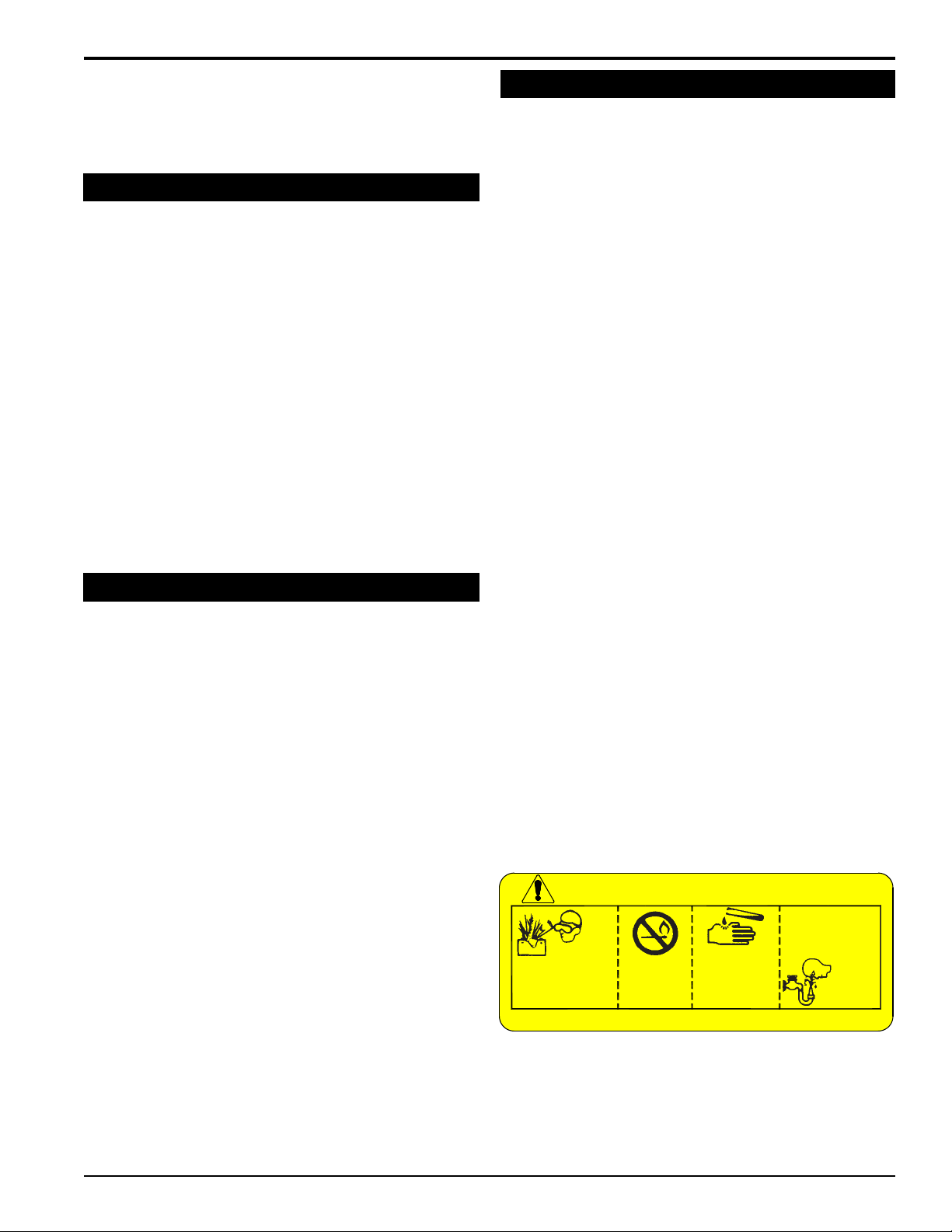
Poison/Danger - Causes Severe Burns. The battery
contains sulfuric acid. Avoid contact with skin, eyes or
clothing. Keep out of reach of children.
• ANTIDOTE-External Contact: Flush immediately
with water.
• ANTIDOTE-Internal: Drink a large amount of water
or milk. Follow with milk of magnesia, beaten egg
or vegetable oil. Call a physician immediately.
• ANTIDOTE-Eye Contact: Flush with water for 15
minutes. Get prompt medical attention.
1. The battery produces explosive gases. Keep sparks,
flame or cigarettes away. Ventilate area when charging
battery. Always wear safety goggles when working
near battery.
2. The battery contains toxic materials. Do not damage
battery case. If case is broken or damaged, avoid
contact with battery contents.
3. Neutralize acid spills with a baking soda and water
solution. Properly dispose of a damaged or worn-out
battery. Check with local authorities for proper disposal
methods.
4. Do not short circuit battery. Severe fumes and fire can
result.
5. Before working with electrical wires or components,
disconnect battery ground (negative) cable first.
Disconnect positive cable second. Reverse this order
when reconnecting battery cables.
DANGER / POISON
FLUSH EYES
IMMEDIATELY
SHIELD EYES
EXPLOSIVE GASES
CAN CAUSE
BLINDNESS OR
INJURY
KEEP OUT OF THE REACH OF CHILDREN. DO NOT TIP. KEEP VENT CAPS TIGHT AND LEVEL.
NO
• SPARKS
• FLAMES
• SMOKING
SULFURIC
ACID
CAN CAUSE
BLINDNESS OR
SEVERE BURNS
WITH WATER
GET
MEDICAL
HELP
FAST
ENGLISH
5 INCH CHIPPER/SHREDDER/BLOWER
3
Page 8
SAFETY
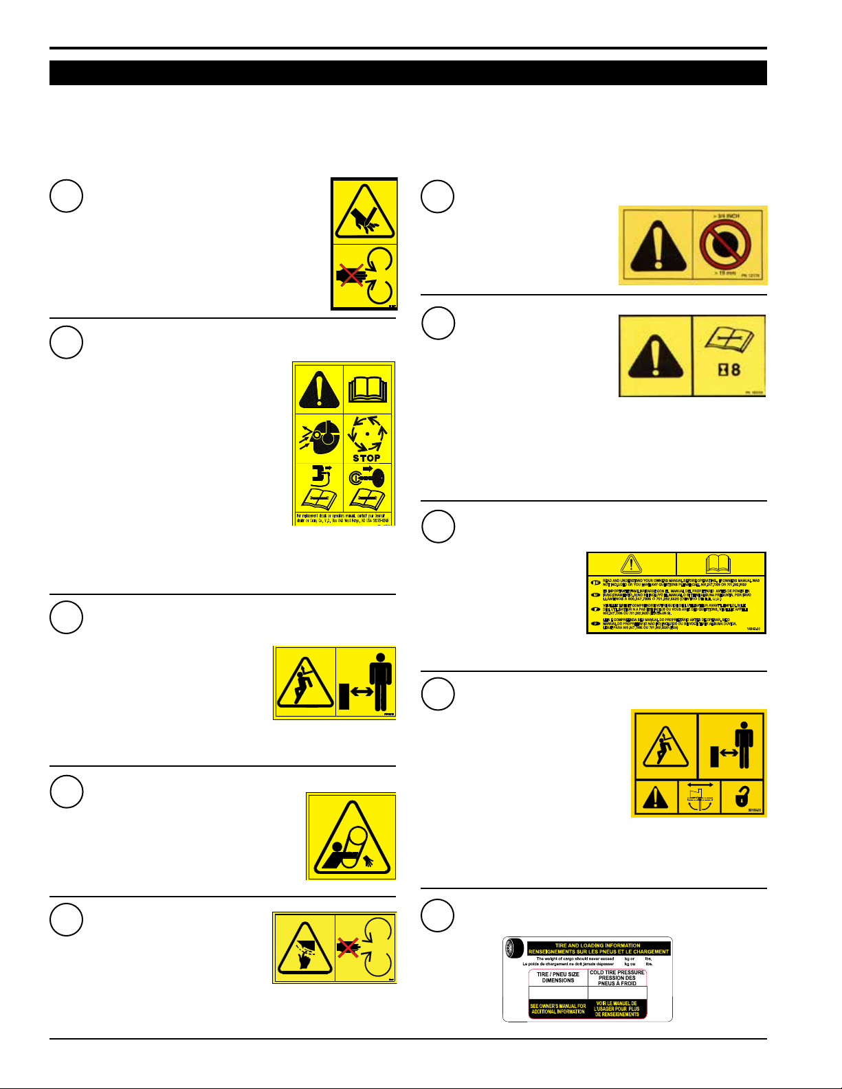
1.8 SAFETY DECALS
See Section 1.9 for decal locations. Familiarize yourself with all of the safety and operating decals on the machine
and the associated hazards. See the engine owner’s manual or contact the engine manufacturer for engine safety
instructions and decals. Make certain that all safety and operational decals on this machine are kept clean and in good
condition. Decals that need replacement must be applied to their original locations.
PN 12169
1
KEEP HANDS AND FEET OUT OF INLET AND
DISCHARGE OPENINGS WHILE MACHINE IS
OPERATING TO AVOID SERIOUS PERSONAL
INJURY. STOP AND ALLOW MACHINE TO
COME TO A COMPLETE STOP BEFORE
CLEARING OBSTRUCTIONS.
PN 12172
2
READ AND UNDERSTAND THIS
OWNER/OPERATORS MANUAL. BE
COMPLETELY FAMILIAR WITH THE
CONTROLS AND THE PROPER USE
OF THIS EQUIPMENT
OBTAIN AND WEAR SAFETY GLASSES
AND USE HEARING PROTECTION AT
ALL TIMES WHEN OPERATING THIS
MACHINE.
BEFORE INSPECTING OR SERVICING
ANY PART OF THIS MACHINE, SHUT
OFF POWER SOURCE, REMOVE THE
KEY, DISCONNECT SPARK PLUG WIRE FROM SPARK PLUG
AND MAKE SURE ALL MOVING PARTS HAVE COME TO A
COMPLETE STOP.
PN 12173
3
DO NOT OPERATE THIS
EQUIPMENT IN THE VICINITY OF
BYSTANDERS. DO NOT ALLOW
CHILDREN TO OPERATE THIS
EQUIPMENT. ALWAYS STAND
CLEAR OF DISCHARGE AREA
WHEN OPERATING THIS MACHINE.
KEEP FACE AND BODY AWAY FROM DISCHARGE AREAS.
PN 12174
4
DO NOT OPERATE MACHINE
WITHOUT SHIELDS IN PLACE.
FAILURE TO DO SO MAY CAUSE
SERIOUS INJURY OR DEATH.
PN 12174
PN 12176
6
DO NOT INSERT BRANCHES
LARGER THAN 3/4 INCH INTO
SHREDDER OR MACHINE
DAMAGE MAY OCCUR.
PN 12250
7
CHECK BLADE BOLTS
FOR PROPER TORQUE
AFTER EVERY 8 HOURS OF
OPERATION. CHECK BLADES
AND ROTATE OR RESHARPEN
DAILY OR AS REQUIRED TO KEEP BLADES SHARP. REFER
TO OWNERS MANUAL FOR INSTRUCTIONS. FAILURE
TO DO SO MAY CAUSE POOR PERFORMANCE, DAMAGE
OR PERSONAL INJURY AND WILL VOID THE MACHINE
WARRANTY.
PN 14942-00
8
CAREFULLY READ THE
USER MANUAL BEFORE
'ACTIVATION. IF THE
USER MANUAL WAS NOT
INCLUDED WITH ANY
QUESTIONS OR CALL
+1-701-282-5520.
9
DO NOT OPERATE THIS
EQUIPMENT IN THE VICINITY
OF BYSTANDERS. DO NOT
ALLOW CHILDREN TO OPERATE
THIS EQUIPMENT. ALWAYS
STAND CLEAR OF DISCHARGE
AREA WHEN OPERATING THIS
MACHINE. KEEP FACE AND BODY
AWAY FROM DISCHARGE AREAS.
ROTATE THE DISCHARGE TUBE OVER THE HITCH
BEFORE TOWING AND LOCK SECURELY IN PLACE.
PN 32109-00
PN 12175
5
KEEP HANDS AND FEET OUT OF
INLET AND DISCHARGE OPENINGS
WHILE MACHINE IS OPERATING
TO AVOID SERIOUS PERSONAL
INJURY. STOP AND ALLOW MACHINE TO COME TO A
COMPLETE STOP BEFORE CLEARING OBSTRUCTIONS.
4
5 INCH CHIPPER/SHREDDER/BLOWER
10
PN 32156-00
5.30-12
23
550 kPa, 80 psi
50
Page 9
SAFETY
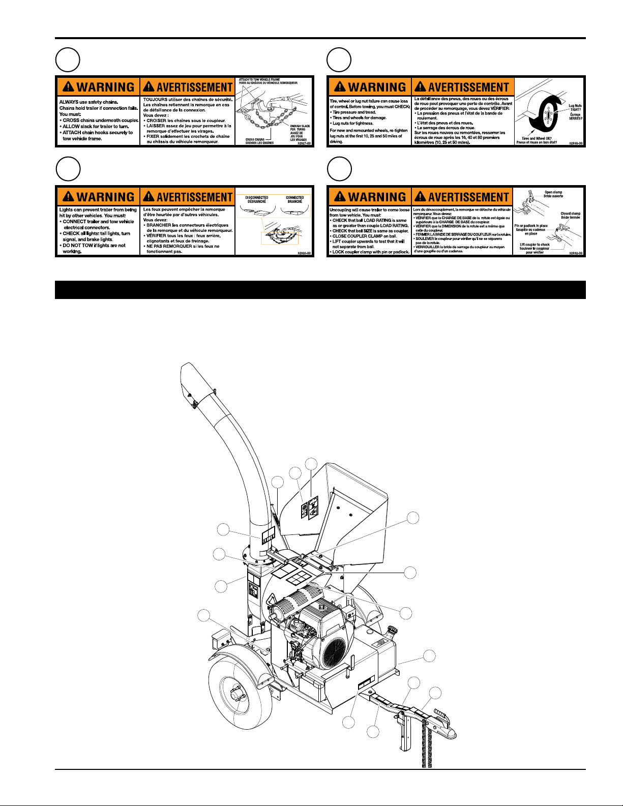
PN 32327-00 Eng & Fr.
11
(32339-00 Esp. & Port)
PN 32328-00 Eng & Fr.
12
(32340-00 Esp. & Port)
*Decals 11-14 not for CE required machines.
PN 32330-00 Eng & Fr.
13
(32342-00 Esp. & Port)
PN 32332-00 Eng & Fr.
14
(32341-00 Esp. & Port)
1.9 SAFETY DECAL LOCATIONS
The numbers below correspond to the decals in Section 1.8. Familiarize yourself with all of the safety and operational
decals on the machine and the associated hazards. See the engine owner’s manual or contact the engine manufacturer
for engine safety instructions and decals. Make certain that all safety and operating decals on this machine are kept
clean and in good condition. Decals that need replacement must be applied to their original locations.
ENGLISH
*Decal located beneath shield
5
6
5
7
9
1
8
3
4
*
13
14
2
10
**
12
11
5 INCH CHIPPER/SHREDDER/BLOWER
5
Page 10

2
Section
ASSEMBLY
2.1 ATTACH TRAILER WHEELS
1. Hold one wheel to a hub and align the wheel lug holes
with the hub lug studs.
2. Thread the lug nuts on the hub studs and tighten to 75
ft-lbs. Follow a star pattern when tightening lug nuts.
3. Repeat for the remaining wheel.
4
2
1
3
3
2
8
10
2.2 ATTACH TRAILER HITCH (NON -CE COMPLIANT)
1. First, attach the hitch pole assembly (10) to the hitch
channel in the trailer deck bottom with two 3/8 x 3 1/4"
bolts (1), washers (2) and nylock nuts (3) and one 3/8
x 3" bolt (4), two washers (2) and nylock nut (3). (See
Figure 2.1.)
2. NOTE: three coated clamps (8) will be used for wiring
harness mounting and routing purposes (Figures 2.1
& 2.3). Place wiring harness in clamps before securing
the clamps in place on the bolts. See Figures 2.1 & 2.3
for clamp locations and mounting details.
3. Next, place the two hitch plates (5) over the axle and
attach to hitch pole using two 1/2 x 3 1/4" bolts (6), four
washers (7) and two centerlock nuts (9) as shown in
Figures 2.1. & 2.2.
8
9
7
6
Figure 2.1, Non-CE compliant model shown
Figure 2.2, Hitch attachment locations
5
8
8
Figure 2.3, Wire Harness routing (CE Compliant model shown)
2.3 ATTACH CHIPPER CHUTE
1. Use a support or hoist to hold the chipper chute in place
on the chipper frame.
2. Mount the chute to the chipper housing using six 3/8 x
1" carriage bolts and nylock nuts.
6
5 INCH CHIPPER/SHREDDER/BLOWER
Page 11

ASSEMBLY
2.4 ATTACH DISCHARGE TUBE
1. Attach one clamping ring (1) and one spacer ring (2) to
discharge tube base (3) using three 3/8 x 1 1/4" bolts
(4) and nylock nuts (5). Tighten leaving 1/16" gap to
assist in mounting to flange. See Figure 2.4.
5
3
2
Figure 2.4, Attach clamp ring and spacer
1
4
5. Lubricate the chute by applying grease to the grease
zerk at the base of the chute. Rotate the chute and
apply grease until the chute rotates freely.
6. Rotate the tube 360 degrees and lock it in place with
the lock pin to make sure it is mounted correctly.
7. Attach the discharge deflector (6) to the discharge tube.
Connect the deflector with two 5/16 X 1 1/4" bolts (7)
through the lower hole in the discharge tube. Run these
bolts through the inside of the tube, washer, deflector,
washer, and then knob (8).
8. Finish bolting the deflector to the tube with two 5/16 x
1" bolts (9) through the end hole in the discharge tube
and secure with 5/16 washers & nylock nuts (10).
6
9
7
10
ENGLISH
2. Slide the tube onto the mounting flange on the chipper
frame. The discharge clamp (1) should slide underneath
the lip of the flange. Tighten the bolts and nuts to
secure it.
3. Install the second half of the spacer (2) and clamp ring
(1) on the discharge tube with 3/8 x 1-1/4" bolts (4) and
nylock nuts (5).
4. Attach lanyard with discharge pin (11) as shown in
Figure 2.5.
11
5
2
1
4
8
Figure 2.6, Attach discharge deflector
Figure 2.5, Attach discharge tube
NOTE
Keep nuts as tight as possible while allowing the
discharge tube to freely turn.
5 INCH CHIPPER/SHREDDER/BLOWER
7
Page 12

ASSEMBLY
UNLEADED
GASOLINE
2.5 ATTACH CHIPPER EXTENSION (CE COMPLIANT MODELS ONLY)
1. Slide the chipper extension into the chipper chute
aligning the mounting holes.
2. Secure using four 5/16" x 3/4” carriage bolts, 5/16”
nylock nuts and 5/16" flat washers. (See Figure 2.7.)
2.8 ADD MOTOR OIL
Check the oil level and, if needed, ll the engine crankcase
with the type and amount of oil specied in the engine
owner’s manual.
Figure 2.7, Chipper extension and Shredder chute tray
2.6 ATTACH SHREDDER CHUTE TRAY
1. Align the shredder chute tray on the shredder chute so
that the chute sits on top of the hinge.
2. Attach the shredder chute with the supplied four 5/16”
x 3/4” carriage bolts, 5/16" nylock nuts and 5/16” flat
washers. (See Figure 2.5.)
2.7 INSTALL A BATTERY
You will need to purchase a battery. Choose a battery that
meets or exceeds the engine manufacturer’s specications.
Consult your engine owner’s manual or authorized dealer
for specication details.
To install the battery:
1. Open the battery box and insert battery into the battery
box.
2. Attach the positive (red) battery cable from the engine
to the positive (+) battery terminal.
3. Attach the negative (black) battery cable from the
engine to the negative (-) battery terminal.
4. Secure the cover on the battery box with the strap.
WARNING
To avoid sparks and a possible explosion or re due
to a short circuit, do not touch the positive (+) battery terminal and any surrounding metal with tools,
jewelry or other metal objects. When installing battery cables, connect the positive (+) cable rst and
the negative (-) cable last.
Figure 2.8, Engine oil ll
2.9 FILL THE FUEL TANK
WARNING
Gasoline and diesel fuels are highly ammable and
their vapors are explosive. To prevent personal
injury or property damage:
Store fuel only in approved containers, in well
ventilated, unoccupied buildings, away from sparks
or ames. A container with a capacity of 2 gallons
or less with a pouring spout is recommended. Do not ll the
fuel tank while the engine is hot or running, since spilled fuel
could ignite if it comes in contact with hot parts or sparks from
ignition. Do not start the engine near spilled fuel. Never use
fuel as a cleaning agent. DO NOT MIX OIL WITH FUEL.
Use only those types of fuels that are recommended in
your engine owner’s manual.
To add fuel:
1. Stop engine, wait for all parts to stop moving and
disconnect spark plug wire. Remove key from key
switch. Allow the engine and muffler to cool for at least
three minutes.
2. Clean area around fuel fill cap and remove cap.
3. Using a clean funnel, fill fuel tank to 1/2” below bottom
of filler neck to provide space for any fuel expansion.
Install fuel fill cap securely and wipe up any spilled
gasoline.
8
5 INCH CHIPPER/SHREDDER/BLOWER
Page 13

3
FEATURES & CONTROLS
Section
Understanding how your machine works will help you achieve the best results when using your machine. The following
descriptions dene the features and controls of your machine.
5
2
ENGLISH
8
3
7
1
4
9
6
5 INCH CHIPPER/SHREDDER/BLOWER
9
Page 14

FEATURES & CONTROLS
1. BELT GUARD
Remove the belt guard to access the drive belt.
2. CHIPPER CHUTE
Feed branches no larger than 5 inches (12.5 cm) in
diameter into the chipper chute
3. DISCHARGE TUBE
Chips and shredded material exit through the discharge
tube. Adjust the position of the discharge tube by rotating
it with the discharge lock. The discharge can be further
adjusted by rotating the discharge cap. Loosen the knobs
located on both sides of the discharge cap and adjust to
desired angle, retighten both knobs..
4. JACK STAND
Always have the jack stand retracted from the ground when
moving the unit. When in use, be sure the jack stand is
down and locked in position with the snap pin.
5. KNIFE ACCESS COVER
The knife access cover is used to access the shredder
knives and chipper blades in order to check them or
remove them for sharpening.
6. OWNER'S MANUAL CONTAINER
Conveniently stores your owner's and parts manuals.
7. SAFETY SWITCH
This machine is equipped with a engine kill safety switch
that prevents the the engine from starting unless the knife
access cover is closed.
8. SHREDDER ADJUSTER
Move the shredder adjuster lever up to produce smaller
sized shredded material. Move the shredder adjuster
lever down to produce larger sized shredded material.
9. SHREDDER CHUTE
Feed sticks and branches no larger than 3/4 inch (2 cm)in
diameter into the shredder chute.
SUBARU ENGINE CONTROLS
1. Engine throttle: Changes engine speed. Refer to engine manual for further engine operating instructions.
2. Engine choke: Use when starting a cold engine. Pull to ON position when starting. Push lever to OFF position when
engine is running.
3. Key switch: Turn to start engine. Do not crank starter for more than ten seconds or damage could result.
10
5 INCH CHIPPER/SHREDDER/BLOWER
Page 15

4
Section
OPERATION
As with any other piece of outdoor power equipment,
getting the feel for how your machine operates and
getting to know the best techniques for particular jobs are
important to good overall performance.
Chipping
The chipping takes place in the smaller, side chute. Feed
branches with a diameter no larger than 5 inches into the
chipper chute. Material fed into the chipper chute is sliced
into small chips and propelled out through the discharge
tube.
Shredding
The shredding takes place in the larger, rear chute. Feed
branches and other yard materials no larger than 3/4 inch
in diameter into the shredder chute. Material fed into the
shredder chute is shredded and propelled out through the
discharge tube.
WARNING
Before operating your machine, be sure you read and
understand all safety, controls and operating instructions in
this Owner/Operator's manual and on your machine. Failure
to follow these instructions can result in serious injury or
property damage.
WARNING
Move machine to a clear, level area outdoors before starting.
Do not operate in the vicinity of bystanders. Make sure cutting
chamber is empty before starting.
4.1 STARTING ENGINE
6. Increase engine RPM to full throttle once belt is
engaged.
For a Cold Engine - gradually return the choke to the OFF
position after the engine starts and warms up.
For a Warm Engine - Use of choke may not be neces-
sary for restart of a warm engine. If it is needed, return
choke to the OFF position once the engine starts.
4.2 OPERATING THE CHIPPER/SHREDDER
After the engine has been started and properly allowed
to warm to an operating temperature, you can begin
operating the chipper. To properly start and operate the
chipper, follow the steps below:
1. AFTER engine is warmed and ready for use, move the
throttle control back to approximately 25% of full throttle.
2. When engine is running at approximately 25% of
full throttle, SLOWLY engage belt by using the belt
engagement lever.
DO NOT engage the belt with engine running at high
RPM.
Engaging belt while engine is running at high
RPM will result in signicant belt squealing and
damage.
Engaging belt while engine is running at high RPM
can also damage vital drive components of the
chipper.
ENGLISH
BEFORE ATTEMPTING TO START THIS MACHINE,
MAKE SURE THE BELT IS DISENGAGED AND THE
HANDLE IS IN THE "START" POSITION.
NEVER ATTEMPT TO START MACHINE WITH THE
DRIVE BELT ENGAGED.
1. Check fuel and engine oil levels before starting.
2. Move the belt engagement lever to START position.
3. Move throttle lever to 1/3 of full throttle. To start a cold
engine, pull the choke ring lever out.
4. Turn key to the START postion. Release the key switch
as soon as the engine starts. Gradually push the choke
ring lever in as the engine warms up.
5. Slowly move belt engagement lever to the CHIPPING
position to engage the rotor.
5 INCH CHIPPER/SHREDDER/BLOWER
3. If the chipper engine stalls while engaging the belt,
return the engagement handle back to the START
position, restart engine, SLIGHTLY increase throttle
and attempt engagement again.
4. Once the belt is engaged, SLOWLY increase throttle
to 100% or full throttle.
5. ALWAYS run the chipper at 100% or full throttle when
chipping material.
4.3 CHIPPER/SHREDDER OPERATION GUIDELINES
1. Limbs fed in to the chipper chute must be 5 inches
12.5 cm) in diameter or less. Trim side branches that
cannot be bent enough to feed into the chipper chute.
Hold small diameter branches together in a bundle and
feed in simultaneously.
11
Page 16

WARNING
DO NOT INSERT BRANCHES LARGER
THAN 3/4 INCH INTO SHREDDER OR
MACHINE DAMAGE MAY OCCUR.
2. ALWAYS run engine at full operating speed before
starting to chip material.
3. Alternate green or fresh cut material with dry
material to lubricate the chipping blades for longer
life and better performance. Chipping dead, dry
material will create heat and dull the chipping blades
quickly.
4. ALWAYS feed brush from the side of the chipper
chute, rather than from the front. Step aside to avoid
being hit by the brush moving into the chipper.
5. ALWAYS place limb, butt end first, into the chipper
chute until it contacts the chipper blades. The actual
feed rate of the limb into the chipper will depend on the
type of material fed and sharpness of the cutting blades.
CAUTION
Obtain and wear safety glasses at all times when operat-
ing the machine.
Do not wear loose fitting clothing.
The operator should always wear heavy boots, gloves,
pants and a long-sleeved shirt.
Use common sense and practice safety to protect your-
self from branches, sharp objects, and other harmful
objects.
6. If the engine slows to where it may stall, stop feeding
material and allow the engine to recover. Feed material
more evenly.
7. If the chipper jams, remove the branch and rotate it
before reinserting it into the chute. Alternately insert
and retract the limb or insert continuously at a rate that
will not kill the engine.
8. NEVER use the belt engagement to clear a plugged
rotor. This may cause belt damage. Refer to the
instructions for clearing a plugged rotor in the Service
and Maintenance section.
9. NEVER attempt to clear a plugged rotor or discharge
with the engine running. ALWAYS shut engine OFF
and remove the spark plug wire before servicing any
part of this machine
10. NEVER attempt to chip pieces of metal, rock, bottles,
cans or other foreign objects.
WARNING
Read and follow all safety instructions in this manual.
Failure to operate the machine in accordance with
the safety instructions MAY RESULT IN PERSONAL
INJURY!
4.4 SLOWING AND STOPPING THE
CHIPPER/SHREDDER DISK AND ENGINE
NEVER disengage the belt as part of the stopping or
shut down process. The belt should remain engaged
during the entire shutdown process.
Leaving the belt engaged is a vital part of proper shutdown and ensures the rotor stops spinning in conjunction with the engine shutting off.
TO PROPERLY SLOW DOWN AND STOP THE DISK
AND ENGINE:
1. WITH THE BELT STILL ENGAGED, SLOWLY move the
throttle to the SLOW position with the belt still engaged.
2. Allow the engine to run at slow idle for 30-60 seconds.
3. Stop the engine by moving the throttle to the STOP
position or turning off the ignition switch.
12
4. Allow disk to come to a complete stop.
5 INCH CHIPPER/SHREDDER/BLOWER
Page 17

5. Once the engine is off and the disk has completely
stopped, the belt can be disengaged by moving the
belt engagement handle back to the START position.
WARNING
Never lean over the chipper chute to push objects into the
cutting device. Use a push stick or brush paddle.
Never use shovels or forks to feed brush. They can
cause extensive damage if they contact the blades.
In addition, metal pieces can be ejected from the
chipper chute and cause serious injury or death.
Never feed brush into the chute with your feet.
Never use hands or feet to clear materials that build up in
the chute.
4.5 OPERATION TIPS
The engine/equipment may be operated during the warm
up period, but it may be necessary to leave the choke partially on until the engine warms up.
OPERATION
ENGLISH
Upon start up, a metallic ticking may occur. This is caused
by the hydraulic lifter Ieakdown during storage. Run the
engine for 5 minutes. The noise will normally cease in
the rst minute. If noise continues, run the engine at midthrottle for 20 minutes. If noise persists, take the engine to
your local authorized Subaru Engine Service Dealer.
If the engine develops sufcient speed to disengage
the starter but does not keep running (a false start), the
engine rotation must be allowed to come to a complete
stop before attempting to restart the engine. If the starter
is engaged while the ywheel is rotating, the starter pinion
and ywheel ring gear may clash resulting in damage to
the starter.
If the starter does not turn the engine over, shut off starter
immediately. Do not make further attempts to start the
engine until the condition is corrected. Do not jump start
using another battery. See your Honda Engine Service
Dealer for service assistance
Do not crank the engine continuously for more than 10
seconds at a time. If the engine does not start, allow a
60-second cool down period between starting attempts.
Failure to follow these guidelines can permanently damage
the starter.
With a new drive belt, the rotor may rotate with the
engagement handle in START position. Within a short
period, the belt will relax and the rotor should disengage.
If the rotor does not disengage even after a short period,
check pulley alignment and idler mechanism or return to
your dealer for service. (See Section 5 for replacing the
drive belt).
5 INCH CHIPPER/SHREDDER/BLOWER
13
Page 18

5
SERVICE & MAINTENANCE
Section
5.1 MAINTENANCE SCHEDULE
The items listed in this service and maintenance schedule are to be checked, and if necessary, corrective action taken.
This schedule is designed for units operating under normal conditions. If the unit is operating in adverse or severe
conditions, it may be necessary for the items to be checked and serviced more frequently.
SEE ENGINE OWNER’S MANUAL FOR FURTHER ENGINE MAINTENANCE AND TROUBLESHOOTING
INFORMATION.
SERVICE AND MAINTENANCE SCHEDULE
FREQUENCY
COMPONENT MAINTENANCE REQUIRED
AIR CLEANER CHECK AND CLEAN (1)
AIR INTAKE CLEAN (1)
ENGINE OIL CHANGE (1)
FUEL FILTER REPLACE
SPARK PLUG CHECK CONDITION AND GAP
ENGINE OIL CHECK/FILL
FUEL TANK CHECK/FILL
ALL INTERNAL AND
EXTERNAL NUTS AND
BOLTS
TIRE PRESSURE CHECK
BATTERY CONNECTIONS CHECK
CHECK TIGHTNESS
REFER TO
ENGINE
OPERATOR’S
MANUAL
BEFORE
EACH
USE
EVERY
8
HOURS
EVERY
25
HOURS
EVERY
50
HOURS
14
CHIPPER ANVIL
CHIPPER BLADES
SHREDDER KNIVES CHECK CONDITION
ENTIRE MACHINE CLEAN
DRIVE BELT CHECK
BELT TENSION CHECK
BELT/PULLEY ALIGNMENT CHECK
GREASE ZERKS LUBE
(1) PERFORM MORE FREQUENTLY UNDER EXTREMELY DUSTY CONDITIONS.
(2) PERFORM MORE FREQUENTLY WHEN CHIPPING DRY OR DIRTY WOOD.
As the Limited Warranty states, failure by the Owner to perform normal maintenance will void the machine’s warranty.
The aggressive, high-speed nature of chipping REQUIRES THE OWNER TO PERFORM THE ABOVE LISTED NORMAL
MAINTENANCE. Special consideration to maintain and re-torque the CHIPPER ANVIL, CHIPPER BLADES, AND ALL
INTERNAL AND EXTERNAL NUTS AND BOLTS is the sole responsibility of the Owner. Failure by the Owner to do so shall
be cause for denial of warranty.
CHECK CLEARANCE AND RETORQUE TO 75 FT-LBS. (2)
CHECK SHARPNESS AND RETORQUE TO 25 FT-LBS (2)
5 INCH CHIPPER/SHREDDER/BLOWER
Page 19

SERVICE & MAINTENANCE
CHIPPING
WARNING
BEFORE INSPECTING OR SERVICING ANY PART OF THIS MACHINE, SHUT OFF POWER SOURCE,
AND MAKE SURE ALL MOVING PARTS HAVE COME TO A COMPLETE STOP.
5.2 CHIPPER BLADE MAINTENANCE
The chipper blades will eventually become dull, making
chipping difcult and adding extra strain on the machine.
CHECK THE SHARPNESS OF THE BLADES EVERY
5 - 15 HOURS OF OPERATION AND SHARPEN AS
NEEDED.
Your blades need to be sharpened if:
• Machine vibrates severely when material is fed into the
chipper.
• Small diameter branches do not self-feed.
• Chips discharge unevenly or have stringy tails, espe-
cially when chipping green branches.
Before you sharpen the chipping blades, check for
permanent damage. Replace the blade if:
• There are cracks, broken corners or nicks greater than
1/8" (see below).
CRACK
GREATER
THAN 1/8”
NICK GREATER
THAN 1/8”
5.3 REMOVING THE BLADES
WARNING
The chipping blades are sharp!! Use care when
working on the machine to avoid injury.
1. Loosen and remove the 3/8” carriage bolt securing the
knife access cover.
2. Open the access cover exposing the chipper shredder
compartment.
3. Rotate the rotor so that the bolts holding the chipper
blade are most accessible.
4. Remove the two hex head bolts holding the blade itself.
Repeat for the second blade. The chipping blades have
two edges per blade and can be reversed one time
each before sharpening. If one side has not been used,
remove and reverse the chipping blades.
5.4 SHARPENING THE BLADES
The blades can be ground on a bench grinder or by a
professional.
1. Never sharpen or grind the mounting surfaces of the
blades. This will cause the edge to roll and the blade will
be damaged, resulting in poor chipping performance.
2. Regrind the angled edge of the chipping blades to 45
degrees (see below). Make sure some type of fixture is
used to correctly hold the blade at the proper angle.
ENGLISH
BROKEN
CORNER
• The base of the cutting edge is worn or has been resharpened so that it no longer extends past the chipping
slot (see below).
CHIPPER
DISC
CHIPPING
SLOT
NEW
BLADE
CHIPPER
DISC
BLADE IS
TOO SHORT,
MUST BE
REPLACED
SLOT
3. Be careful when grinding so that the blade does not
become overheated and change color. This will remove
the heat-treated properties.
4. Use short grinding times and cool with water or some
type of liquid coolant.
5. Remove an equal amount off each blade to maintain
rotor balance.
6. Small imperfections such as nicks and burrs on the flat
side of the blade will not affect the chipping performance
of the machine.
7. For blades that have been repeatedly sharpened,
ensure that the sharpened surface extends past the
chipping slot opening. If it does not extend past the
opening, the blades should be replaced.
MOUNTING SURFACE
45°
.25
(DO NOT GRIND)
SHARPENED
SURFACE
MOUNTING SURFACE
(DO NOT GRIND)
SHARPENED
SURFACE
5 INCH CHIPPER/SHREDDER/BLOWER
15
Page 20

SERVICE & MAINTENANCE
BEFORE INSPECTING OR SERVICING ANY PART OF THIS MACHINE, SHUT OFF POWER SOURCE,
AND MAKE SURE ALL MOVING PARTS HAVE COME TO A COMPLETE STOP.
WARNING
5.5 LUBRICATION
IMPORTANT
Polyurea and lithium-based greases are not compatible.
Mixing the two grease types may lead to premature
failure.
Lubricate the machine periodically with a lithium-based
grease. Extreme working conditions will require more
frequent greasing.
Grease the following points every 50 hours of operating
time:
NOTE
Do not over grease bearings. Overlling can lead to
excessive heat and/or unseating of the seals. Add
grease slowly and under light pressure. Whenever
possible, rotate bearing slowly while lubricating.
Figure 5.1, Discharge chute
Figure 5.3, Two bolt ange bearing on rotor shaft
5.6 SETTING CHIPPING BLADE CLEARANCE
The chipping blades should clear the anvil by 1/16" but
not more than 1/8". Check the clearance every 8 hours
of operation and adjust if needed. The chipping anvil
is reversible. All four sides of the anvil can be used for
chipping.
To adjust the anvil:
1. Loosen and remove the 3/8” carriage bolt securing the
knife access cover.
2. Open the knife access cover exposing the chipper
shredder compartment.
3. Remove the dust cover on the front side of the machine.
4. Remove the belt guards on the rear of the machine.
5. Loosen the set screws holding the lock collars on the
front and rear 2-bolt flange bearings.
6. Use a punch and hammer to tap the lock collars directly
opposite normal rotation. (On the front side, tap punch
in a CW rotation. On the rear side, tap punch in a
CCW rotation
7. Using a rubber mallet, tap the end of the rotor shaft to
obtain 1/16” to 1/8” clearance. Rotate the rotor and
check the clearance on all chipping blades.
Figure 5.2, Two bolt ange bearing on rotor shaft (drive side)
16
5 INCH CHIPPER/SHREDDER/BLOWER
Page 21

SERVICE & MAINTENANCE
WARNING
BEFORE INSPECTING OR SERVICING ANY PART OF THIS MACHINE, SHUT OFF POWER SOURCE,
AND MAKE SURE ALL MOVING PARTS HAVE COME TO A COMPLETE STOP.
1/16" TO 1/8"
CLEARANCE
CHIPPER
BLADE
Figure 5.4, Required chipper blade clearance
CHOP
BLOCK
(view from top of chipper)
8. Once clearance has been set, the lock collars must
be replaced and retightened. Using a punch and a
hammer, rotate the lock collars in the direction of shaft
rotation (i.e. counter-clockwise on the rear bearing
and clockwise on the front bearing) and set them with
a positive hammer tap. Tighten the lock collar set
screws.
9. Loosen the set screws holding the belt pulley on the
rotor shaft. Move the pulley on the shaft so it is aligned
with the engine drive pulley. The pulley should be
moved an equal but opposite amount that the rotor
was moved.
10. Insure the pulley drive key is completely seated under
the pulley and tighten the set screws.
11. Check pulley alignment by laying a straight-edge across
the pulley faces. Pulley faces should line up. If not,
determine which pulley to adjust and repeat alignment
check.
12. Replace the belt guard and plastic bearing cap.
5.7 REPLACING SHREDDER KNIVES
To replace shredder knives or spacers, order Shredder
Knife Kit, 77613-00.
ENGLISH
Follow the complete installation instructions, 77614-00.
NOTE
Never reuse the #10-24 bolts, nuts or shafts. Always install
new parts when replacing knives or blades.
5.8 SHREDDER KNIFE MAINTENANCE
Do not attempt to sharpen shredder knives. Inspect the
knives often for signs of damage.
If a knife has any sign of cracking or is broken in any way,
it should be replaced immediately. (For service, Shredder
Knife Kit, 77613-00.)
Figure. 5.5, Examples of damage to knives
5 INCH CHIPPER/SHREDDER/BLOWER
17
Page 22

SERVICE & MAINTENANCE
BEFORE INSPECTING OR SERVICING ANY PART OF THIS MACHINE, SHUT OFF POWER SOURCE,
AND MAKE SURE ALL MOVING PARTS HAVE COME TO A COMPLETE STOP.
WARNING
5.9 CLEARING A PLUGGED ROTOR
WARNING
If the machine becomes plugged, shut off the engine,
disconnect the spark plug wire and allow the machine
to come to a complete stop before clearing debris.
Do not operate machine without proper guards and
screens in place.
1. Stop engine, disengage rotor clutch and allow machine
to come to a complete stop. Remove the spark plug
wire.
2. Loosen and remove the 3/8” carriage bolts securing
the chipper access cover.
3. Open the knife access cover, exposing the chipper
shredder compartment.
Figure 5.7, Rotor access
5.10 REMOVING THE ROTOR
Loosen and remove the 3/8” carriage bolt securing the
knife access cover.
1. Open the access cover, exposing the chipper shredder
compartment.
2. Loosen the bushing bolts holding the drive pulley to the
shaft and remove the pulley.
3. Loosen the set screw in the lock collars. Using a punch
and hammer, tap the lock collars in a direction opposite
of normal rotation so that they can be removed.
4. Unbolt bearings and lift rotor out of machine.
5. Remove bearings from rotor shaft.
6. Re-install rotor assembly and bearings and tighten bolts
to proper torque.
5.11 REPLACING THE DRIVE BELT
Check the condition of the drive belt annually or after every
25 hours of operation, whichever comes rst. If the belt is
cracked, worn, frayed, or stretched, replace it. To replace
the belt:
1. Stop engine, disengage rotor clutch and allow machine
to come to a complete stop. Remove the spark plug
wire.
2. Place the engagement handle in the START position.
3. Remove the 5/16 x 3/4" bolts and washers securing
the shields in place and remove shields.
Figure 5.6, Rotor access
4. Clean the debris out of the shredding rotor and/or
chipper top discharge area and tube. Turn the rotor by
hand to be sure it is free to rotate.
5. Replace spark plug wire, restart engine and resume
operation.
18
5 INCH CHIPPER/SHREDDER/BLOWER
Figure 5.7, Drive belt on rotor pulley
Page 23

WARNING
BEFORE INSPECTING OR SERVICING ANY PART OF THIS MACHINE, SHUT OFF POWER SOURCE,
AND MAKE SURE ALL MOVING PARTS HAVE COME TO A COMPLETE STOP.
Figure 5.8, Drive belt on engine pulleys
4. Slip the drive belt off the pulleys. If necessary, loosen
the engine bolts and slide the engine forward to allow
the belt to slip off the pulley.
SERVICE & MAINTENANCE
8. Check pulley alignment. Place a straightedge across
the face of both pulleys to inspect. If necessary, loosen
the set screws on both pulleys and move them so that
they are directly in line. Be sure that the idler pulley
contacts near the center of the belt. Retighten the
pulley set screws.
9. Replace upper and lower belt guards. Allow 1/8 inch
clearance between top of belt and inside of lower belt
guard. Make sure all bolts, nuts and fasteners are
properly torqued to 20 ft.-lbs.
5.12 TRAILER SERVICE TIPS
1. Check wheel bolt torque monthly.
2. Check air pressure in tires monthly.
3. Check and repack wheel bearings with grease every
12 months.
4. When towing, always connect the safety chains. Make
sure trailer hitch bolts are tight.
5. Check trailer lights periodically.
ENGLISH
Figure 5.9, Engine plate adjustment bolts
5. Inspect pulleys for wear. Replace the pulleys if they
are cracked or worn enough that the belt contact area
is not smooth and flat.
6. Place new belt over pulleys. Do not force or pry the
belt over pulleys as this may cause cord breakage. If
necessary, loosen engine mounting bolts and tip the
engine forward to allow the belt to be easily placed
over the pulley.
7. Align the engine so the crankshaft is parallel to the
rotor shaft. Tighten engine mounting bolts to 20 ft.-lbs.
torque.
5 INCH CHIPPER/SHREDDER/BLOWER
19
Page 24

6
TROUBLESHOOTING
Section
Before performing any of the corrections in this troubleshooting chart, refer to the correct safety precautions and operating or maintenance procedures. Contact your nearest dealer for service problems with the machine.
PROBLEM POSSIBLE CAUSES REMEDY
Improper control settings. Use proper settings.
Lack of fuel. Fill fuel tank.
Engine will not start.
Engine or rotor stalls or
stops.
Chipper does not chip.
Engine overheats.
Spark plug disconnected. Connect spark plug.
Dirty, stale or contaminated gas. Refill gas tank with fresh, clean unleaded regular gasoline.
Internal engine problems. See your dealer.
Obstructed discharge. Use branch or similar object to clear discharge.
Plugged rotor. Clear rotor. Feed material more evenly.
Feeding material that is too
large.
Dull chipper blades. Rotate or sharpen blades.
Drive belts loose or worn. Inspect drive belts, adjust or replace if needed.
Attempting to feed branches
that are too large.
Broken or missing chipper
blades
Cooling system plugged. Clean cooling fan and fins.
Improper oil level. Fill engine to correct oil level. Refer to the engine owners manual.
Reduce size of material.
Limit branch size to 5 inches in diameter.
Replace blade.
Hard to feed chipper;
requires excessive power
to chip.
Shredder requires
excessive power or stalls.
20
Dull chipper blades. Reverse or sharpen blades.
Obstructed discharge. Use branch or similar object to clear discharge.
Improper blade clearance. Adjust clearance between chipper anvil and chipper blades.
Obstructed discharge. Use branch or similar object to clear discharge.
Plugged rotor. Clear rotor, feed material into shredder more evenly.
Wet or green material will not
discharge.
5 INCH CHIPPER/SHREDDER/BLOWER
Alternately feed dry material.
Page 25

Engine stalls or belt
squeals when engaging
clutch.
TROUBLESHOOTING
Engaging clutch too fast. Engage clutch more slowly.
Plugged rotor. Clear rotor. Feed material more evenly.
Belt tension too loose. Replace belt or spring.
Material from chipper
wraps around rotor shaft
Excessive vibration while
running.
Rotor will not turn.
Cannot engage clutch.
Stringy, green material
bypasses chipper blades.
Dull chipper blades. Sharpen blades.
Improper blade clearance. Adjust clearance between anvil and chipper blades.
Drive system vibration.
Rotor out of balance.
Chipper blade to anvil clearance
is incorrect.
Drive belt too loose or broken. Replace belt or spring.
Obstructed discharge. Use branch or similar object to clear discharge.
Plugged rotor. Clear rotor. Feed material more evenly.
Improper belt installation; belt
not under belt guide.
Improper belt tension. Adjust belt tension. Replace belt or spring if needed.
Rotate branch or material when feeding to cut completely.
Check drive belts and pulleys for bad or worn areas. Check for
dull chipper blades or shredder knives.
Inspect rotor for broken or missing chipper blades and shredder
knives; replace if needed. Check rotor to see if it wobbles.
Check to see if rotor is assembled correctly.
Set chipper blade/anvil clearance to recommended distance (1/16”
to 1/8”).
Install belt properly; install belt under belt guide.
ENGLISH
Excessive belt wear.
Trailer sways during
towing.
Not using correct belt.
Pulley(s) damaged or worn. Replace pulley(s).
Pulley(s) not in alignment. Align pulley(s) with straight edge.
Belt(s) tension too loose. Replace belt or spring.
Tire air pressure not correct Check tire sidewall for inflation limits.
Contact your nearest authorized dealer to order the correct belt for
your chipper/shredder.
5 INCH CHIPPER/SHREDDER/BLOWER
21
Page 26

7
Section
SPECIFICATIONS
SC5720B
DESCRIPTION English Metric
OVERALL SIZE 92" X 52" X 92" 233cm X 131cm X 233cm
OVERALL WEIGHT 930 lbs 422 kg
MAX CHIPPER CAPACITY 5" 12.7cm
CHIPPER BLADES 4 4
MAX SHREDDER CAPACITY 3/4" 2 cm
SHREDDER KNIVES 36 36
ROTOR SPEED 2000 RPM 2000 RPM
ROTOR SIZE 18" 46 cm
ROTOR WEIGHT 121 lbs 54.9 kg
DRIVE TYPE BELT BELT
BELT SIZE 2RB40 2RB40
TIRE SIZE 5.3 -12 5.3 -12
ENGINE 720cc SUBARU 720cc SUBARU
FUEL TANK CAPACITY 9 gallons 34.1 liters
SPECIAL TORQUE REQUIREMENTS
DIAGRAM
LOCATION
A
B ON ROTOR KNIFE SHAFTS
ON ROTOR PLATE, BLADE
MOUNTING BOLTS
LOCATION ON
MACHINE
5/16" X 1" HEX HD. GRADE
8 BOLTS (QTY 8)
10-24 X 1-1/8" SCREW
(QTY 8)
A
HARDWARE
DESCRIPTION
B
TORQUE
(UNIFIED INCH)
25 Ft.-lbs. 34 Nm
36 In.-lbs. 4 Nm
TORQUE
(METRIC)
22
5 INCH CHIPPER/SHREDDER/BLOWER
Page 27

SPECIFICATIONS
BOLT TORQUE
The tables below are for reference purposes only and their use by anyone is entirely voluntary, unless otherwise noted.
Reliance on their content for any purpose is at the sole risk of that person and any loss or damage resulting from the
use of this information is the responsibility of that person.
SAE
SAE - 2
SAE - 5
SAE - 8
BOLT DIAMETER
Grade
and
Head
A
Markings
ENGLISH
BOLT DIAMETER (A)
1/4” 7.5 5.5 11 8 16 12
5/16” 15 11 23 17 34 25
3/8” 27 20 41 30 61 45
7/16” 41 30 68 50 95 70
1/2” 68 50 102 75 149 110
9/16” 97 70 149 110 203 150
5/8” 122 90 203 150 312 230
3/4” 217 160 353 260 515 380
7/8” 230 170 542 400 814 600
1” 298 220 786 580 1220 900
1-1/8” 407 300 1085 800 1736 1280
1-1/4” 570 420 2631 1940 2468 1820
SAE 2 SAE 5 SAE 8
N.m Ft-lb. N.m Ft-lb. N.m Ft-lb.
BOLT TORQUE *
ENGLISH
METRIC
Grade
and
Head
Markings
4.8
4.8
8.8
8.8 10.9
10.9
12.9
12.9
BOLT DIAMETER
A
METRIC
BOLT DIAMETER
(A)
M3 0.5 0.4 - - - - - -
M4 3 2.2 - - - - - -
M5 5 4 - - - - - -
M6 6 4.5 11 8.5 17 12 19 14.5
M8 15 11 28 20 40 30 47 35
M10 29 21 55 40 80 60 95 70
M12 50 37 95 70 140 105 165 120
M14 80 60 150 11 0 225 165 260 190
M16 125 92 240 175 350 255 400 300
M18 175 125 330 250 475 350 560 410
M20 240 180 475 350 675 500 800 580
M22 330 250 650 475 925 675 1075 800
M24 425 310 825 600 1150 850 1350 1000
M27 625 450 1200 875 1700 1250 2000 1500
4.8 8.8 10.9 12.9
N.m Ft-lb. N.m Ft-lb. N.m Ft-lb. N.m Ft-lb.
* Torque value for bolts and capscrews are identified by their head markings.
Torque figures indicated above are valid for non-greased or non-oiled threads and heads unless otherwise specified. Therefore, do not
grease or oil bolts or capscrews unless otherwise specified in this manual. When using locking elements, increase torque values by 5%.
BOLT TORQUE *
5 INCH CHIPPER/SHREDDER/BLOWER
23
Page 28

8
Section
OPTIONS
Part # DECSCRIPTION
72493 CHIPPER BLADE KIT
77613-00 SHREDDER KNIFE KIT
KIT, CHIPPER BLADE, 72493
KIT, SHREDDER KNIVES, 77613-00
24
5 INCH CHIPPER/SHREDDER/BLOWER
Page 29

EPA EMISSION CONTROL WARRANTY STATEMENT
YOUR WARRANTY RIGHTS AND OBLIGATIONS
Crary Industries Inc. is pleased to explain the evaporative emission
control system (EECS) warranty on your 2013 equipment. New
equipment must be designed, built and equipped to meet the EPA’s
stringent anti-smog standards. Crary Industries Inc. must warrant the
EECS on your equipment for the period of time listed below provided
there has been no abuse, neglect or improper maintenance of your
equipment.
Your EECS may include parts such as the fuel tank, fuel lines, fuel
caps, vapor hoses, and clamps.
Where a warrantable condition exists, Crary Industries Inc. will repair
your equipment at no cost to you including diagnosis, parts and labor.
MANUFACTURER’S WARRANTY COVERAGE:
This evaporative emission control system is warranted for two years. If
any evaporative emission-related part on your equipment is defective,
the part will be repaired or replaced by Crary Industries Inc.
OWNER’S WARRANTY RESPONSIBILTIES:
As the equipment owner, you are responsible for performance of the
required maintenance listed in your owner’s manual. Crary Industries
Inc. recommends that you retain all receipts covering maintenance on
your equipment, but Crary Industries Inc. cannot deny warranty solely
for the lack of receipts.
As the equipment owner, you should however be aware that Crary
Industries Inc. may deny you warranty coverage if your equipment or
a part has failed due to abuse, neglect, or improper maintenance or
unapproved modications.
You are responsible for presenting your equipment to Crary Industries
Inc.’s distribution center or service center as soon as the problem
exists. The warranty repairs should be completed in a reasonable
amount of time, not to exceed 30 days. If you have a question regarding
your warranty coverage, you should contact Justin Banyai at 1-701-
282-5520.
GERERAL EMISSIONS WARRANTY COVERAGE:
Crary Industries Inc. warrants to the ultimate purchaser and each
subsequent purchaser that the equipment is:
Designed, built and equipped so as to conform with all applicable
regulations; and
Free from defects in materials and workmanship that cause the failure
of a warranted part to be identical in all material respects to that part as
described in Crary Industries Inc.’s application for certication.
The warranty period begins on the date the equipment is delivered to
an ultimate purchaser or rst placed into service. The warranty period is
two years.
Subject to certain conditions and exclusions as stated below, the
warranty on emission-related parts is as follows:
(1) Any warranted part that is not scheduled for replacement as
required maintenance in the written instructions supplied, is warranted
for the warranty period stated above. If the part fails during the period
of warranty coverage, the part will be repaired or replaced by Crary
Industries Inc. according to subsection (4) below. Any such part
repaired or replaced under warranty will be warranted for the remainder
of the period.
(2) Any warranted part that is scheduled only for regular
inspection in the written instructions supplied is warranted for the
warranty period stated above. Any such part repaired or replaced under
warranty will be warranted for the remaining warranty period.
(3) Any warranted part that is scheduled for replacement as
required maintenance in the written instructions supplied is warranted
for the period of time before the rst scheduled replacement date for
that part. If the part fails before the rst scheduled replacement, the
part will be repaired or replaced by Crary Industries Inc. according
to subsection (4) below. Any such part repaired or replaced under
warranty will be warranted for the remainder of the period prior to the
rst scheduled replacement point for the part.
(4) Repair or replacement of any warranted part under the
warranty provisions herein must be performed at a warranty station at
no charge to the owner.
(5) Notwithstanding the provisions herein, warranty services
or repairs will be provided at all of our distribution centers that are
franchised to service the subject engines or equipment.
(6) The equipment owner will not be charged for diagnostic
labor that is directly associated with diagnosis of a defective, emissionrelated warranted part, provided that such diagnostic work is performed
at a warranty station.
(7) Crary Industries Inc. is liable for damages to other engine or
equipment components proximately caused by a failure under warranty
of any warranted part.
(8) Throughout the equipment warranty period stated above,
Crary Industries Inc. will maintain a supply of warranted parts sufcient
to meet the expected demand for such parts.
(9) Any replacement part may be used in the performance of any
warranty maintenance or repairs and must be provided without charge
to the owner. Such use will not reduce the warranty obligations of Crary
Industries Inc.
(10) Add-on or modied parts that are not exempted by the EPA
may not be used. The use of any non-exempted add-on or modied
parts by the ultimate purchaser will be grounds for disallowing a
warranty claim. Crary Industries Inc. will not be liable to warrant failures
of warranted parts caused by the use of a non-exempted add-on or
modied part.
WARRANTED PARTS:
The repair or replacement of any warranted part otherwise eligible for
warranty coverage may be excluded from such warranty coverage
if Crary Industries Inc. demonstrates that the equipment has been
abused, neglected, or improperly maintained, and that such abuse,
neglect, or improper maintenance was the direct cause of the need for
repair or replacement of the part. That notwithstanding, any adjustment
of a component that has a factory installed, and properly operating,
adjustment limiting device is still eligible for warranty coverage. The
following emission warranty parts are covered:
(1) Fuel Tank
(2) Fuel Cap
(3) Fuel Line
(4) Clamps
(5) Vapor Hose
Page 30

ECHO BEAR CAT
www.bearcatproducts.com
237 NW 12th Street, West Fargo, ND 58078-0849
Phone: 701.282.5520 • Toll Free:
E-mail: service@bearcatproducts.com • sales@bearcatproducts.com
888.625.4520 • Fax: 701.282.9522
 Loading...