

Page 1

2.75 INCH
CHIPPER/SHREDDER
SC2206 - 206 cc BRIGGS & STRATTON
ENGLISH FRANÇAIS
ESPAÑOL
Manual P/N: 18910-00
Rev. 022509
SN Range: 0 - A09531
OWNER'S/PARTS MANUAL
Page 2

Before You Begin
MANUFACTURED BY CRARY INDUSTRIES
MANUFACTURED IN U.S.A.
XXXXXX
WEST FARGO, NORTH DAKOTA 58078 U.S.A.
SERIAL NUMBER
DEAR ECHO BEAR CAT CUSTOMER
Thank you for purchasing a ECHO Bear Cat product. The ECHO Bear Cat line is designed, tested, and manufactured
to give years of dependable performance. To keep your machine operating at peak efciency, it is necessary to adjust
it correctly and make regular inspections. The following pages will assist you in the operation and maintenance of your
machine. Please read and understand this manual before operating your machine.
If you have any questions or comments about this manual, please call us toll-free at 1-800-247-7335.
If you have any questions or problems with your machine, please call or write your local authorized ECHO Bear Cat
Dealer.
This document is based on information available at the time of its publication. ECHO Bear Cat is continually making
improvements and developing new equipment. In doing so, we reserve the right to make changes or add improvements
to our product without obligation for equipment previously sold.
PLEASE SEND US YOUR WARRANTY CARD
A warranty card is included in your owner's kit packaged with your machine. Please take the time to ll in the information
requested on the card. When you send your completed card to us, we will register your machine and start your
coverage under our limited warranty.
FOR MACHINE SERVICE OR PARTS:
For service assistance, contact your nearest authorized
ECHO Bear Cat dealer or the factory. For parts, contact
your authorized dealer. Your dealer will need to know the
serial number of your machine to provide the most efcient
service. See below for information on how to identify and
record the serial number for your machine.
FOR ENGINE SERVICE OR PARTS:
For engine service or parts, contact your nearest authorized
engine dealer. ECHO Bear Cat does not handle any parts,
repairs or warranties for engines.
SERIAL NUMBER LOCATION
Please record the serial number in the space provided and
on the warranty and registration card.
ORDERING PARTS
Only genuine ECHO Bear Cat replacement parts should
be used to repair the machine. Replacement parts
manufactured by others could present safety hazards,
even though they may t on this machine. Replacement
parts are available from your ECHO Bear Cat dealer.
Provide the following when ordering parts:
The SERIAL NUMBER of your machine.
The PART NUMBER of the part.
The PART DESCRIPTION.
The QUANTITY needed.
SERIAL NUMBER
HOW TO CONTACT ECHO BEAR CAT
ADDRESS PHONE E-MAIL HOURS
237 NW 12th Street
P.O. Box 849
West Fargo, ND 58078
*Original Instructions
© 2009, CRARY INDUSTRIES, ALL RIGHTS RESERVED. PRODUCED AND PRINTED IN THE U.S.A.
800.247.7335
701.282.5520
FAX: 701.282.9522
sales@bearcatproducts.com
service@bearcatproducts.com
Monday - Friday,
8 am to 5 pm
Central Time
Page 3

LIMITED WARRANTY
This warranty applies to all AG and Outdoor Power Equipment manufactured by Crary Industries.
Crary Industries warrants to the original owner each new Crary Industries product to be free from defects
in material and workmanship, under normal use and service. The warranty shall extend 1 year from date of
delivery for income producing (commercial) applications and 2 years from date of delivery for non-income
producing (consumer) use of the product. The product is warranted to the original owner as evidenced by a
completed warranty registration on file at Crary Industries. Replacement parts are warranted for (90) days
from date of installation.
THE WARRANTY REGISTRATION MUST BE COMPLETED AND RETURNED TO CRARY INDUSTRIES
WITHIN 10 DAYS OF DELIVERY OF THE PRODUCT TO THE ORIGINAL OWNER OR THE WARRANTY
WILL BE VOID.
In the event of a failure, return the product, at your cost, along with proof of purchase to the selling Crary
Industries dealer. Crary Industries will, at its option, repair or replace any parts found to be defective in material
or workmanship. Warranty on any repairs will not extend beyond the product warranty. Repair or attempted
repair by anyone other than a Crary Industries dealer as well as subsequent failure or damage that may occur
as a result of that work will not be paid under this warranty. Crary Industries does not warrant replacement
components not manufactured or sold by Crary Industries.
This warranty applies only to parts or components that are defective in material or workmanship. 1.
This warranty does not cover normal wear items including but not limited to bearings, belts, pulleys, filters 2.
and chipper knives.
ENGLISH
This warranty does not cover normal maintenance, service or adjustments.3.
This warranty does not cover depreciation or damage due to misuse, negligence, accident or improper 4.
maintenance.
This warranty does not cover damage due to improper setup, installation or adjustment.5.
This warranty does not cover damage due to unauthorized modifications of the product. 6.
Engines are warranted by the respective engine manufacturer and are not covered by this warranty.7.
Crary Industries is not liable for any property damage, personal injury or death resulting from the unauthorized
modification or alteration of a Crary product or from the owner’s failure to assemble, install, maintain or operate
the product in accordance with the provisions of the Owner’s manual.
Crary Industries is not liable for indirect, incidental or consequential damages or injuries including but not
limited to loss of crops, loss of profits, rental of substitute equipment or other commercial loss.
This warranty gives you specific legal rights. You may have other rights that may vary from area to area.
Crary Industries makes no warranties, representations or promises, expressed or implied as to the performance
of its products other than those set forth in this warranty. Neither the dealer nor any other person has any
authority to make any representations, warranties or promises on behalf of Crary Industries or to modify the
terms or limitations of this warranty in any way. Crary Industries, at its discretion, may periodically offer limited,
written enhancements to this warranty.
CRARY INDUSTRIES RESERVES THE RIGHT TO CHANGE THE DESIGN AND/OR SPECIFICATIONS
OF ITS PRODUCTS AT ANY TIME WITHOUT OBLIGATION TO PREVIOUS PURCHASERS OF ITS
PRODUCTS.
Page 4

CONTENTS
SECTION DESCRIPTION PAGE
SAFETY .......................................................................................................... 1
1.1 SAFETY ALERT SYMBOL ..............................................................................1
1.2 EMISSION INFORMATION .............................................................................1
1.3 BEFORE OPERATING ...................................................................................1
1.4 OPERATION SAFETY ....................................................................................2
1.5 MAINTENANCE AND STORAGE SAFETY ........................................................2
1.6 SAFETY DECAL LOCATIONS .........................................................................3
1.7 SAFETY DECALS ............................................................................................4
ASSEMBLY .................................................................................................... 5
2.1 IDENTIFY LOOSE HARDWARE .....................................................................5
2.2 ATTACH HITCH AND STAND .........................................................................5
2.3 ATTACH WHEELS AND AXLE ........................................................................5
2.4 ATTACH FLAP.................................................................................................6
2.6 ATTACH HOPPER TO CHIPPER BODY ........................................................6
2.5 ATTACH MANUAL HOLDER ...........................................................................6
2.7 FILL THE TANK ...............................................................................................6
2.8 CHECK/ADD MOTOR OIL TO ENGINE .........................................................6
FEATURES & CONTROLS ............................................................................7
OPERATION ................................................................................................... 8
4.1 STARTING THE CHIPPER/SHREDDER .........................................................8
4.2 STOPPING THE CHIPPER/SHREDDER ........................................................8
4.3 OPERATING THE CHIPPER/SHREDDER ......................................................9
SERVICE & MAINTENANCE ....................................................................... 10
5.1 MAINTENANCE SCHEDULE ........................................................................10
5.2 CHIPPER BLADE MAINTENANCE ...............................................................10
5.3 REMOVING THE CHIPPER BLADES ..........................................................11
5.4 SHARPENING THE BLADES .......................................................................11
5.5 REPLACING SHREDDER KNIVES ..............................................................12
5.6 CLEARING A PLUGGED ROTOR ................................................................12
5.7 CHANGING THE DISCHARGE SCREEN ....................................................12
5.8 REMOVING THE ROTOR ............................................................................12
TROUBLESHOOTING .................................................................................13
SPECIFICATIONS ........................................................................................14
7.1 SPECIAL TORQUE REQUIREMENTS .........................................................14
7.2 BOLT TORQUE .............................................................................................15
PARTS ..........................................................................................................16
8.1 PARTS ORDERING INFORMATION ............................................................16
8.3 OWNERS KIT, OPTIONAL EQUIPMENT, SERVICE PARTS .......................16
8.2 REPLACEMENT PARTS...............................................................................16
8.4 HOPPER ASSEMBLY ...................................................................................17
8.5 MAIN ASSEMBLY ........................................................................................18
8.6 ROTOR ASSEMBLY .....................................................................................20
Page 5
1
Section
SAFETY
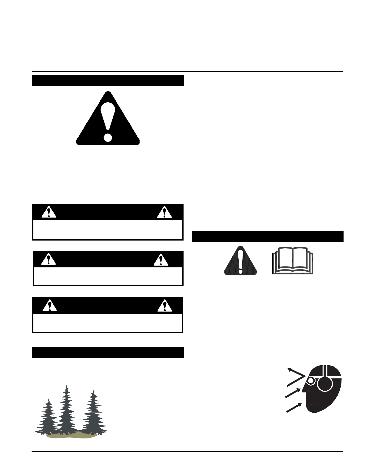
1.1 SAFETY ALERT SYMBOL
The Owner/Operator’s manual uses this symbol to alert
you of potential hazards. Whenever you see this symbol,
read and obey the safety message that follows it. Failure
to obey the safety message could result in personal injury,
death or property damage.
DANGER
Indicates an imminently hazardous situation that, if not
avoided, will result in death or serious injury.
The engine on your power equipment, like most outdoor
power equipment, is an internal combustion engine that
burns gasoline or diesel fuel (hydrocarbons). Therefore,
your power equipment must be equipped with a spark
arrester mufer in continuous effective working order. The
spark arrester must be attached to the engine exhaust
system in such a manner that ames or heat from the
system will not ignite ammable material.
Failure of the owner/operator of the equipment to comply
with this regulation is a misdemeanor under California law
and may also be a violation of other state and/or federal
regulations, laws, ordinances, or codes. Contact your
local re marshal or forest service for specic information
about which regulations apply in your area.
The standard mufer installed on the engine is not
equipped with a spark arrester. One must be added
before using this machine in an area where a spark
arrester is required by law. Contact the local authorities
if these laws apply to you. See your authorized engine
dealer for spark arrester options.
1.3 BEFORE OPERATING
ENGLISH
WARNING
Indicates a potentially hazardous situation that, if
not avoided, could result in death or serious injury.
CAUTION
Indicates a potentially hazardous situation that, if not
avoided, may result in minor or moderate injury.
1.2 EMISSION INFORMATION
Under California Law and the laws of several other states,
you are not permitted to operate an internal combustion
engine using hydrocarbon
fuels on any forest
covered, brush covered or
grass covered land or on
land covered with grain,
hay or other ammable
agricultural crops, without
an engine spark arrester
in continuous effective
working order.
2.75 INCH CHIPPER/SHREDDER
Read and understand this owner’s manual. Be 1.
completely familiar with the controls and the proper
use of this equipment.
Familiarize yourself with all of the safety and operating 2.
decals on this equipment and on any of its attachments
or accessories.
Keep safety decals clean and legible. Replace missing 3.
or illegible safety decals.
Obtain and wear safety glasses and use hearing 4.
protection at all times when operating this machine.
Avoi d wearing loose fitted 5.
clothing. Never operate this
machine while wearing clothing
with drawstrings that could
wrap around or get caught in
the machine.
Do not operate this machine 6.
if you are under the influence
of alcohol, medications, or substances that can affect
your vision, balance or judgement. Do not operate if
tired or ill. You must be in good health to operate this
machine safely.
1
Page 6

SAFETY
Do not operate this equipment in the vicinity of 7.
bystanders. Keep the area of operation clear of all
persons, particularly small children. It is recommended
that bystanders keep at least 50 feet (15 meters) away
from the area of operation.
Do not allow children to operate this equipment.8.
Use only in daylight or good artificial light.9.
Do not run this equipment in an enclosed area. Engine 10.
exhaust contains carbon monoxide gas, a deadly
poison that is odorless, colorless and tasteless. Do not
operate this equipment in or near buildings, windows
or air conditioners.
Always use an approved fuel container. Do not remove 11.
gas cap or add fuel when engine is running. Add fuel
to a cool engine only.
Do not fill fuel tank indoors. Keep open flames, sparks, 12.
smoking materials and other sources of combustion
away from fuel.
Do not operate machine without shields in place. 13.
Failure to do so may cause serious injury or death.
Keep all guards, deflectors, and shields in good working 14.
condition.
Before inspecting or servicing any part of this machine, 15.
shut off the machine and make sure all moving parts
have come to a complete stop. Disconnect the battery
and remove the ignition key where applicable.
Check that all screws, nuts, bolts, and other fasteners 16.
are secured, tightened and in proper working condition
before starting the machine.
Do not transport or move machine while it is operating 17.
or running.
The disk will continue to rotate after being disengaged. 6.
Shut off the machine and make sure all moving parts
have come to a complete stop before inspecting or
servicing any part of the machine. Disconnect the
battery and remove the ignition key if applicable.
Do not insert branches with a diameter larger than the 7.
max chipper capacity into machine or machine damage
may occur.
When feeding material into machine, do not allow metal, 8.
rocks, bottles, cans or any other foreign material to be
fed into the machine.
Ensure debris does not blow into traffic, parked cars, 9.
or pedestrians.
Kee p the mach i ne clear of de bris and other 10.
accumulations.
Do not allow processed material to build up in the 11.
discharge area. This may prevent proper discharge
and can result in kickback of material through the feed
opening.
If the machine becomes clogged, the cutting mechanism 12.
strikes any foreign object, or the machine starts
vibrating or making an unusual noise, shut off machine
immediately and make sure all moving parts have come
to a complete stop. Disconnect the battery and remove
the ignition key if applicable. After the machine stops: A)
Inspect for damage, B) Replace or repair any damaged
parts, and C) Check for and tighten any loose parts.
On electric start models, disconnect cables from battery 13.
before doing any inspection or service. Remove key.
Check blade bolts for proper torque after every 8 hours 14.
of operation. Check blades and rotate or resharpen
daily or as required to keep blades sharp. Failure to do
so may cause poor performance, damage or personal
injury and will void the machine warranty.
1.4 OPERATION SAFETY
Always stand clear of discharge area when operating 1.
this machine. Keep face and body away from feed
and discharge openings.
Keep hands and feet out of feed and discharge openings 2.
while machine is operating to
avoid serious personal injury.
Stop and allow machine to come
to a complete stop before clearing
obstructions.
Set up your work site so you 3.
are not endangering traffic and
the public. Take great care to provide adequate
warnings.
Do not climb on machine when operating. Keep proper 4.
balance and footing at all times.
Check cutting chamber to verify it is empty before 5.
starting the machine.
2
2.75 INCH CHIPPER/SHREDDER
1.5 MAINTENANCE AND STORAGE SAFETY
Before inspecting, servicing, storing, or changing 1.
an accessory, shut off the machine and make sure
all moving parts have come to a complete stop.
Disconnect the battery and remove the ignition key
where applicable.
Replace any missing or unreadable safety decals. 2.
Refer to the safety decal section for part numbers.
Allow machine to cool before storing in an enclosure.3.
Store the machine out of reach of children and where 4.
fuel vapors will not reach an open flame or spark.
Never store this machine with fuel in the fuel tank 5.
inside a building where fumes may be ignited by an
open flame or spark. Ignition sources can be hot water
and space heaters, furnaces, clothes dryers, stoves,
electric motors, etc.
Drain the fuel and dispose of it in a safe manner for 6.
storage periods of three months or more.
Page 7
SAFETY
4
4
4
5
3
2
1
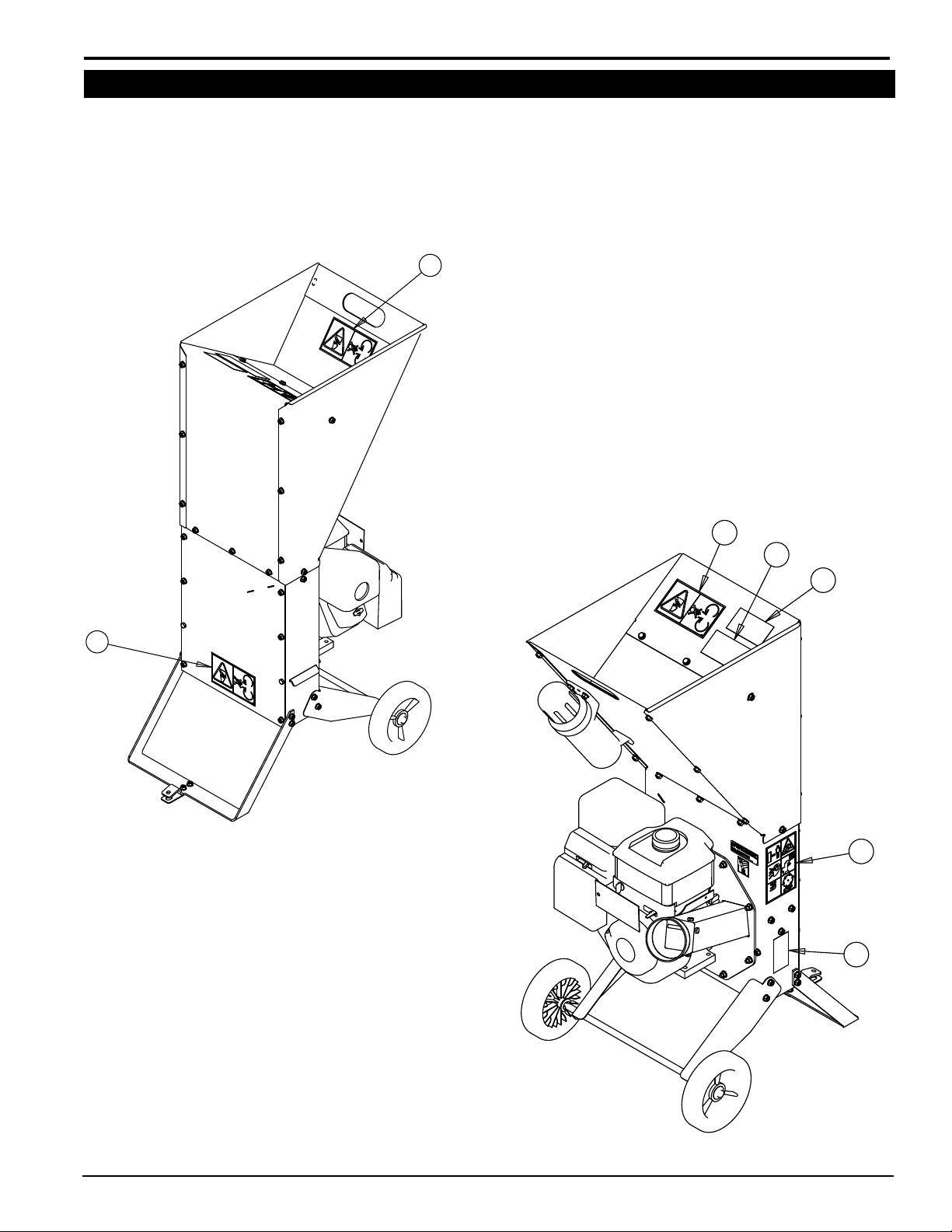
1.6 SAFETY DECAL LOCATIONS
The numbers below correspond to the decals in Section 1.7. Familiarize yourself with all of the safety and operational
decals on the machine and the associated hazards. See the engine owner’s manual or contact the engine manufacturer
for engine safety instructions and decals. Make certain that all safety and operating decals on this machine are kept
clean and in good condition. Decals that need replacement must be applied to their original locations.
ENGLISH
2.75 INCH CHIPPER/SHREDDER
3
Page 8
SAFETY
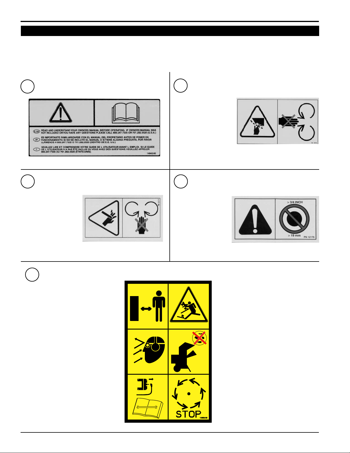
1.7 SAFETY DECALS
See Section 1.6 for decal locations. Familiarize yourself with all of the safety and operating decals on the machine
and the associated hazards. See the engine owner’s manual or contact the engine manufacturer for engine safety
instructions and decals. Make certain that all safety and operational decals on this machine are kept clean and in good
condition. Decals that need replacement must be applied to their original locations.
P/N 12175
P/N 14942-00
1
4
KEEP HANDS AND FEET
OUT OF INLET AND DISCHARGE OPENINGS
WHILE MACHINE IS
OPERATING TO AVOID
SERIOUS PERSONAL
INJURY. STOP AND
ALLOW MACHINE
TO COME TO A COMPLETE STOP BEFORE CLEARING
OBSTRUCTIONS.
2
KEEP HANDS AND
FEET OUT OF INLET
AND DISCHARGE
OPENINGS WHILE MACHINE IS OPERATING
TO AVOID SERIOUS
PERSONAL INJURY.
STOP AND ALLOW
MACHINE TO COME TO A COMPLETE STOP BEFORE
CLEARING OBSTRUCTIONS.
DO NOT OPERATE THIS EQUIPMENT
IN THE VICINITY OF BYSTANDERS. DO
NOT ALLOW CHILDREN TO OPERATE
THIS EQUIPMENT.
OBTAIN AND WEAR SAFETY GLASSES
AND USE HEARING PROTECTION AT ALL
TIMES WHEN OPERATING THIS MACHINE.
BEFORE INSPECTING OR SERVICING ANY PART OF THIS MACHINE, SHUT OFF POWER SOURCE,
DISCONNECT SPARK PLUG WIRE
FROM SPARK PLUG AND MAKE SURE
ALL MOVING PARTS HAVE COME TO A
COMPLETE STOP.
P/N 12171
3
P/N 14965-00
P/N 12176
5
DO NOT INSERT
BRANCHES LARGER
THAN 3/4 INCH INTO
SHREDDER OR MACHINE DAMAGE MAY
OCCUR.
ALWAYS STAND CLEAR OF
DISCHARGE AREA WHEN OPERATING
THIS MACHINE. KEEP FACE AND BODY
AWAY FROM FEED AND DISCHARGE
OPENINGS.
WHEN FEEDING SHREDDABLE
MATERIAL INTO CHIPPER, DO NOT
ALLOW METAL, ROCKS, BOTTLES,
CANS OR ANY OTHER FOREIGN
MATERIAL TO BE FED INTO CHIPPER
OR SHREDDER.
BEFORE INSPECTING OR SERVICING
ANY PART OF THIS MACHINE, SHUT
OFF POWER SOURCE, DISCONNECT
SPARK PLUG WIRE FROM SPARK PLUG
AND MAKE SURE ALL MOVING PARTS
HAVE COME TO A COMPLETE STOP.
4
2.75 INCH CHIPPER/SHREDDER
Page 9
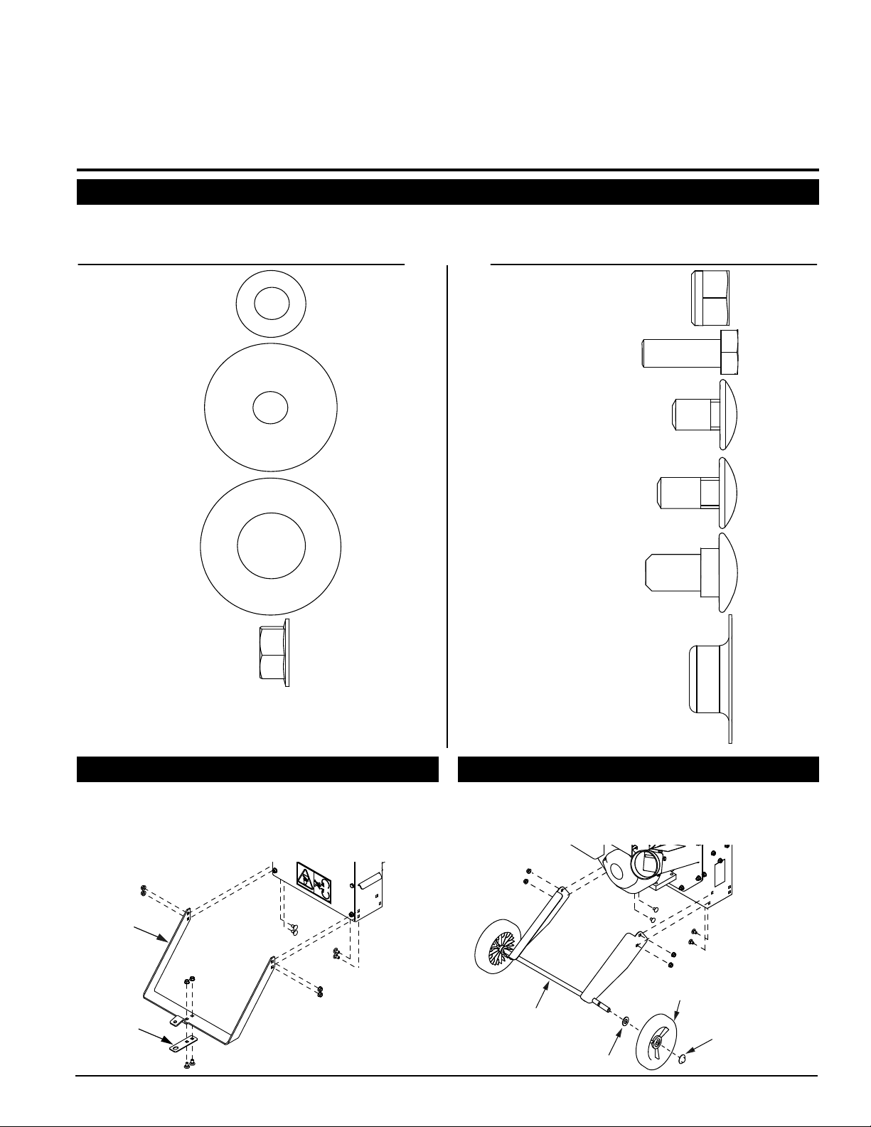
5/16” Flange Nut
3/4” Carriage Bolt
5/16” Flat Washer
5/16” Fender
Washer
3/4” Hex Bolt
1/2” Carriage Bolt
5/8” Carriage Bolt
DESCRIPTION QTY. DESCRIPTION QTY.
5/8” Flat Washer
3
3
2
30
5/8” Pushnut
3
24
6
3
3
5/16” Nylock Nut
6
[NOTE: EUROPEAN MODELS HAVE TWO EXTRA 5/16” NUTS AND
WASHERS AND TWO 3-1/2” HEX BOLTS. THREAD THESE BOLTS
THROUGH THE HOLES IN THE CHIPPER CHUTE OPENING AND SECURE
WITH THE WASHERS AND NUTS AS AN EXTRA SAFETY MEASURE.]
2
HITCH
STAND
AXLE
WASHER
WHEEL
PUSHNUT
Section
ASSEMBLY
2.1 IDENTIFY LOOSE HARDWARE
Identify the loose hardware in the owner's kit using the guide below. All hardware is shown to scale.
TOOLS NEEDED: 1/2" wrench, 1/2" socket, ratchet.
ENGLISH
2.2 ATTACH HITCH AND STAND
Attach the hitch to the stand with two (2) 5/8" carriage 1.
bolts and ange nuts.
Attach the stand to the chipper body with four (4) 5/8" 2.
carriage bolts and ange nuts.
2.75 INCH CHIPPER/SHREDDER
2.3 ATTACH WHEELS AND AXLE
Attach wheels to the axle with two (2) at washers and
pushnuts. Bolt the axle on to the chipper body with four
(4) 1/2" carriage bolts and ange nuts.
5
Page 10

SAFETY
1
2
3
4
FLAP
MANUAL HOLDER
2.4 ATTACH FLAP
Attach the rubber ap to the angled hopper side with three
(3) 3/4" hex bolts, fender washers and nylock nuts.
2.6 ATTACH HOPPER TO CHIPPER BODY
2.5 ATTACH MANUAL HOLDER
Attach manual holder to the hopper panel with the handle using
three (3) 3/4" carriage bolts, nylock nuts and at washers.
2.7 FILL THE TANK
Bolt the hopper panels to the chipper body and assemble
the hopper in the order shown below using 1/2" carriage
bolts and serrated ange nuts. The angled side panels
should be bolted on top of the rectangular panels. Thread
the carriage bolts from the inside of the machine through
the chipper body and hopper. Secure them on the outside
of the chipper with ange nuts.
WARNING
Gasoline and diesel fuels are highly
ammable and their vapors are explosive. To
prevent personal injury or property damage:
Store fuel only in approved containers, in
well ventilated, unoccupied buildings, away
from sparks or ames. A container with a capacity of 2
gallons or less with a pouring spout is recommended.
Do not ll the fuel tank while the engine is hot or running,
since spilled fuel could ignite if it comes in contact with
hot parts or sparks from ignition. Do not start the engine
near spilled fuel. Never use fuel as a cleaning agent.
DO NOT MIX OIL WITH FUEL.
Use only those types of fuels that are recommended in
your engine owner’s manual.
To add fuel:
Stop engine, wait for all parts to stop moving and 1.
disconnect spark plug wire. Remove key from key
switch. Allow the engine and muffler to cool for at least
three minutes.
Clean area around fuel fill cap and remove cap.2.
Using a clean funnel, fill fuel tank to 1/2” below bottom 3.
of filler neck to provide space for any fuel expansion.
Install fuel fill cap securely and wipe up any spilled
gasoline.
2.8 CHECK/ADD MOTOR OIL TO ENGINE
Check the oil level and if needed ll the engine crankcase
with the type and amount of oil specied in the engine
owners manual.
6
2.75 INCH CHIPPER/SHREDDER
Page 11

3
SHREDDER
CHUTE
CHIPPER
CHUTE
DISCHARGE CHUTE
TRANSPORT
HANDLE
MANUAL HOLDER
RECOIL STARTER
GAS TANK
CAP
OIL DIPSTICK
Section
FEATURES & CONTROLS
Understanding how your machine works will help you
achieve the best results when using your chipper/shred-
der. The following descriptions dene the features and
controls of your machine.
CHIPPER CHUTE
Feed branches no larger than 2.75 inches in diameter into
the chipper chute.
DISCHARGE CHUTE
Chipped and shredded materials are discharged onto the
ground through the discharge chute.
GAS TANK CAP
Check the gas level before each use.
MANUAL HOLDER
Conveniently stores your Owner's Manual.
OIL DIPSTICK
Check the oil level before each use by removing the dipstick.
RECOIL STARTER
Used to start engine. Grasp handle and pull out to start.
Refer to engine manual for further engine operating
instructions.
SHREDDER CHUTE
Feed sticks and branches no larger than ¾ inch in diameter
into the shredder chute.
TRANSPORT HANDLE
Used to move machine. Grasp handle, tip machine back
onto its wheels and push or pull machine to desired location.
Never transport or move machine with engine running.
ENGLISH
2.75 INCH CHIPPER/SHREDDER
7
Page 12

4
OPERATION
Section
As with any other piece of outdoor power equipment, getting the feel for how your machine operates and getting to
know the best techniques for particular jobs are important
to overall good performance.
CHIPPING OPERATION
Feed materials to be chipped into the smaller, side chute.
Chipping materials should be no larger than 2-3/4 inch
in diameter. The material is sliced into small chips and
propelled out through a discharge screen.
SHREDDING OPERATION
Feed material to be shredded into the larger, top chute.
Shredding materials should be no larger than 3/4 inch
in diameter. The material is shredded, and propelled out
through the discharge chute onto the ground.
WARNING
Before operating your machine, be sure you read and
understand all safety, controls and operating instructions in this Owner/Operators manual and on your machine. Failure to follow these instructions can result in
serious injury or property damage.
WARNING
WARNING
Move machine to a clear, level area outdoors
before starting. Do not operate in the vicinity of
bystanders. Make sure cutting chamber is empty
before starting.
4.2 STOPPING THE CHIPPER/SHREDDER4.1 STARTING THE CHIPPER/SHREDDER
Move the machine to a clear, level area outdoors before
starting. Do not operate in the vicinity of bystanders.
Make sure the cutting chamber is empty before starting.
Check engine oil level before starting.1.
Turn the fuel shut-off valve to the ON position.2.
Move the choke control lever to the 3. CHOKE position.
Move the throttle control lever to the FAST position. 4.
Pull the recoil starter until the engine starts. Make 5.
sure the starting cord retracts.
For a Cold Engine:6. Gradually return the choke
control to the off position after the engine starts and
warms up. The machine may be operated during the
warm up period, but it may be necessary to leave
the choke partially on until the engine warms up.
For a Warm Engine: Return choke to the off position
as soon as engine starts.
Move the throttle control lever to SLOW position. 1.
Allow the engine to run at idle for 30-60 seconds.2.
Stop the engine by moving the throttle to the 3. STOP
position.
Turn the fuel shut-off valve to the OFF position.4.
Allow machine to come to a complete stop.5.
Fig. 4.1 Choke control lever
8
2.75 INCH CHIPPER/SHREDDER
Fig. 4.2 Fuel shut-off valve and throttle control lever
Page 13

OPERATION
4.3 OPERATING THE CHIPPER/SHREDDER
WARNING
Read and follow all safety instructions in this manual.
Failure to operate the machine in accordance with
the safety instructions MAY RESULT IN PERSONAL
INJURY!
CAUTION
Obtain and wear safety glasses at all times when
operating the machine.
Do not wear loose fitting clothing.
The operator should always wear heavy boots, gloves,
pants and a long-sleeved shirt.
Use common sense and practice safety to protect
yourself from branches, sharp objects, and other
harmful objects.
WARNING
Never lean over the chipper chute to push objects
into the cutting device. Use a push stick or brush
paddle.
Never use shovels or forks to feed brush. They can
cause extensive damage if they contact the blades.
In addition, metal pieces can be ejected from the
chipper chute and cause serious injury or death.
Never feed brush into the chute with your feet.
Never use hands or feet to clear materials that build up in
the chute.
The machine chips and shreds a variety of materials into
a more readily decomposed or handled condition. The
following guidelines will help you get started.
Run unit at full operating speed1. before starting to
chip material.
Limbs fed in to the chipper chute must be 2.75 2.
inches (7 cm) in diameter or less. Trim side branches
that cannot be bent enough to feed into the chipper
chute. Hold small diameter branches together in a
bundle and feed in simultaneously.
Material fed into the shredder chute must be ¾ 3.
inches (2 cm) in diameter or less. Common shredding
materials include grass, leaves, garden refuse, sticks,
and small branches.
Exclude pieces of metal, rocks, bottles, cans, and 4.
other foreign objects when feeding material into the
machine.
Feed brush from the side of the chipper chute, 5. rather
than from the front. Step aside to avoid being hit by the
brush moving into the chipper.
Place limb, butt end first, into the chipper chute 6. until
it contacts the chipper blades. The actual feed rate
of the limb into the chipper will depend on the type of
material fed and sharpness of the cutting blades.
If the engine slows to where it may stall, 7. stop feeding
material and allow the engine to recover. Feed material
more evenly.
If the chipper jams,8. remove the branch and rotate it
before reinserting it into the chute. Alternately insert
and retract the limb or insert continuously at a rate that
will not kill the engine.
Do not use the clutch to clear a plugged rotor. 9. This
may cause belt damage. Refer to the instructions for
clearing a plugged rotor in the Service and Maintenance
section.
Alternate greener material with dry material10. to
lubricate the chipping blades for longer life and better
performance. Chipping dead, dry material will create
heat and dull the chipping blades quickly.
Sharpen the chipping blades periodically.11. Check
the sharpness of the blades every 5-15 hours. Refer
to the Service and Maintenance section for sharpening
instructions.
ENGLISH
2.75 INCH CHIPPER/SHREDDER
9
Page 14

5
SERVICE & MAINTENANCE
Section
5.1 MAINTENANCE SCHEDULE
The items listed in this service and maintenance schedule are to be checked, and if necessary, corrective action taken.
This schedule is designed for units operating under normal conditions. If the unit is operating in adverse or severe
conditions, it may be necessary for the items to be checked and serviced more frequently.
SEE ENGINE OWNER’S MANUAL FOR FURTHER ENGINE MAINTENANCE AND TROUBLESHOOTING
INFORMATION.
SERVICE AND MAINTENANCE SCHEDULE
FREQUENCY
COMPONENT
AIR CLEANER CHECK AND CLEAN (1)
ENGINE OIL CHANGE (1)
SPARK PLUG CHECK CONDITION AND GAP
ENGINE OIL CHECK/FILL
FUEL TANK CHECK/FILL
ALL INTERNAL AND EXTERNAL
NUTS AND BOLTS
CHIPPER BLADES
SHREDDER KNIVES CHECK CONDITION
ENTIRE MACHINE CLEAN
(1) PERFORM MORE FREQUENTLY UNDER EXTREMELY DUSTY CONDITIONS.
(2) PERFORM MORE FREQUENTLY WHEN CHIPPING DRY OR DIRTY WOOD.
As the Limited Warranty states, failure by the Owner to perform normal maintenance will void the machine’s
warranty. The aggressive, high-speed nature of chipping REQUIRES THE OWNER TO PERFORM THE ABOVE
LISTED NORMAL MAINTENANCE. Special consideration to maintain and re-torque the CHIPPER BLADES, AND
ALL INTERNAL AND EXTERNAL NUTS AND BOLTS is the sole responsibility of the Owner. Failure by the Owner
to do so shall be cause for denial of warranty.
MAINTENANCE
REQUIRED
CHECK TIGHTNESS
CHECK SHARPNESS AND RETORQUE TO 25 FT-LBS (2)
REFER TO ENGINE
OPERATOR’S MANUAL
BEFORE
EACH USE
EVERY 8
HOURS
5.2 CHIPPER BLADE MAINTENANCE
WARNING
Do not tip the machine all the way over on its side when
servicing.
WARNING
The chipping blades are sharp! Use care when working
on the machine to avoid injury.
10
2.75 INCH CHIPPER/SHREDDER
The chipper blades will eventually become dull, making
chipping difcult and adding extra strain on the machine.
CHECK THE SHARPNESS OF THE BLADES EVERY
5 - 15 HOURS OF OPERATION AND SHARPEN AS
NEEDED.
Your blades need to be sharpened if:
• Machine vibrates severely when material is fed into the
chipper.
• Small diameter branches do not self-feed.
• Chips discharge unevenly or have stringy tails,
especially when chipping green branches.
Page 15

SERVICE & MAINTENANCE
45°
.25
MOUNTING SURFACE
(DO NOT GRIND)
MOUNTING SURFACE
(DO NOT GRIND)
SHARPENED
SURFACE
SHARPENED
SURFACE
NICK GREATER
THAN 1/8”
CRACK
GREATER
THAN 1/8”
BROKEN
CORNER
CHIPPING
SLOT
NEW
BLADE
CHIPPER
DISC
BLADE IS
TOO SHORT,
MUST BE
REPLACED
CHIPPER
DISC
CHIPPING
SLOT
WARNING
BEFORE INSPECTING OR SERVICING ANY PART OF THIS MACHINE, SHUT OFF POWER SOURCE,
AND MAKE SURE ALL MOVING PARTS HAVE COME TO A COMPLETE STOP.
Before you sharpen the chipping blades, check for
permanent damage. Replace the blade if:
• There are cracks, broken corners or nicks greater than
1/8" (see below).
• The base of the cutting edge is worn or has been re-
sharpened so that it no longer extends past the chipping
slot (see below).
Inspect blade to see if cracks or nicks are visible. If 3.
cracks are present, the blade cannot be resharpened
and must be discarded (see Sec. 5.2).
If the other side of the blade has not been used yet, 4.
the blade can be rotated so that the new edge is in
position and reused.
If both sides of the blade have been used, it must be 5.
resharpened. The blades can be ground on a bench
grinder (see Sec 5.4) or by a professional.
Replace blade on the rotor. Note correct orientation 6.
of cutting edge to rotor (see Sec. 7.1).
Secure with two 5/16" x 1/2" bolts and torque to 25 ft-lb. 7.
Repeat steps 2-7 for the second blade.8.
5.4 SHARPENING THE BLADES
The blades can be ground on a bench grinder or by a
professional.
1. Never sharpen or grind the mounting surfaces of the
blades. This will cause the edge to roll and the blade will
be damaged, resulting in poor chipping performance.
ENGLISH
5.3 REMOVING THE CHIPPER BLADES
Remove the eight 1.
5/16" nuts holding
th e e n g i n e a n d
plate to the frame
(see Fig. 5.1) and
remove the engine
a n d p lat e f r o m
frame.
To remove a blade, 2.
remove the two 5/8"
bolts securing the
blade to the rotor.
Note the relation of
blade cutting edge
to rotor.
Fig. 5.1 Remove these bolts and four
on other side
2. Regrind the angled edge of the chipping blades to 45
degrees (Figure 5.2). Make sure some type of fixture is
used to correctly hold the blade at the proper angle.
3. Be careful when grinding so that the blade does not
become overheated and change color. This will remove
the heat-treated properties.
4. Use short grinding times and cool with water or some
type of liquid coolant.
5. Remove an equal amount off each blade to maintain
rotor balance.
6. Small imperfections such as nicks and burrs on the flat
side of the blade will not affect the chipping performance
of the machine.
7. For blades that have been repeatedly sharpened,
ensure that the sharpened surface extends past the
chipping slot opening. If it does not extend past the
opening, the blades should be replaced.
2.75 INCH CHIPPER/SHREDDER
Fig. 5.2 - Double-Edged Blade
11
Page 16

SERVICE & MAINTENANCE
REMOVE
SCREW
REMOVE
NYLOCK
NUT
.75 x .75
SPACERS
.75 x .90
SPACER
SHAFT
DISCHARGE
SCREEN BOLTS
DISCHARGE
SCREEN NUTS
LEFT
RIGHT
WARNING
BEFORE INSPECTING OR SERVICING ANY PART OF THIS MACHINE, SHUT OFF POWER SOURCE,
AND MAKE SURE ALL MOVING PARTS HAVE COME TO A COMPLETE STOP.
5.5 REPLACING SHREDDER KNIVES
CAUTION
Never reuse the #10-24 nut and bolt. Never reuse
shafts or spacers if they show signs of wear or abuse.
Always install new parts when repairing.
The serrated shredder knives are designed to offer long
life and can be reversed if they become dull. For a
replacement kit, refer to the Parts Section.
To reverse the knives or install a new shredder knife kit,
proceed as follows:
Remove the eight 5/16" nuts holding the engine and 1.
plate to the frame (see Figure 5.1).
Remove engine, plate and rotor assembly from frame.2.
Working one shaft at a time, remove the 10-24 x 1-1/8" 3.
screw and 10-24 nylock nut from the knife spacer
located on the shaft.
Push the shaft out of the rotor assembly and remove 4.
the knife spacers. Keep track of the order the spacers
are installed on the shafts so they are returned to the
original location (see Figure 5.3). If the spacers and knife
sections are not installed properly, the rotor will be out of
balance and will not have proper shredding action.
Reverse and reinstall the existing knives and spacers 5.
or install new knife sections and spacers onto the shaft.
Secure the shaft with a new 10-24 x 1-1/8" screw and
10-24 nylock nut. Torque to 36 in-lb.
Repeat for the remaining shaft.6.
Replace engine, plate and rotor assembly and secure 7.
with eight 5/16" nuts.
Remove 2. left nut and bolt holding the discharge screen
in place (see Fig. 5.4).
Reach up into the discharge chute and pivot that side 3.
of the discharge screen down.
Clean any trash or debris from the screen area, being 4.
careful not to touch the sharp blades.
Pivot the screen back up to its original position.5.
Secure with the 5/16" nut and 5-1/2" bolt.6.
5.7 CHANGING THE DISCHARGE SCREEN
There is one optional discharge screen available with a
smaller mesh that will produce smaller-sized shredded
product. Refer to the Parts Section for this screen. To
change the discharge screen, proceed as follows:
Remove the two 5/16" nuts and 5-1/2" bolts securing 1.
the discharge screen and pull the discharge screen
out from the bottom.
Clean any trash or debris from the screen area.2.
Insert the replacement screen into the bottom of the 3.
chipper body.
Secure with two 5/16" x 5-1/2" bolts and 5/16" nuts.4.
Fig. 5.3 Shredder knife and spacer arrangement on shaft
5.6 CLEARING A PLUGGED ROTOR
If too much material is fed into the chipper/shredder or
if the material is too large, the machine may become
plugged. To clear a plugged rotor, proceed as follows:
Turn off the machine and let all moving parts come to 1.
a complete stop.
12
Fig. 5.4 Removing the discharge screen
5.8 REMOVING THE ROTOR
Remove the eight 5/16" nuts holding the engine and 1.
plate to the frame (see Figure 5.1).
Remove engine, plate and rotor assembly from the 2.
frame.
Th e rotor is connected direct ly to th e engine 3.
crankshaft. If the rotor needs servicing, remove the
5/16-24 x 2-1/2" bolt, 5/16" spring washer and the two
set screws and key securing it to the crankshaft.
Pull the rotor assembly off the crankshaft.4.
Reverse the procedure to install the rotor.5.
2.75 INCH CHIPPER/SHREDDER
Page 17

6
Section
TROUBLESHOOTING
Before performing any of the corrections in this troubleshooting chart, refer to the appropriate information contained in
this manual for the correct safety precautions and operating or maintenance procedures. Contact your dealer or the
factory for service problems with the machine.
PROBLEM POSSIBLE CAUSES REMEDY
Improper control settings. Use proper settings.
Lack of fuel. Fill fuel tank.
Engine will not start.
Engine or rotor stalls
or stops.
Chipper does not chip.
Engine overheats.
Spark plug disconnected. Connect spark plug.
Dirty, stale or contaminated gas. Refill gas tank with fresh, clean unleaded regular gasoline.
Internal engine problems. See your dealer.
Obstructed discharge. Use branch or similar object to clear discharge.
Plugged rotor. Clear rotor. Feed material more evenly.
Feeding material that is too
large.
Dull chipper blades. Rotate or sharpen blades.
Drive belts loose or worn. Inspect drive belts, adjust or replace if needed.
Attempting to feed branches
that are too large.
Broken or missing chipper
blades
Cooling system plugged. Clean cooling fan and fins.
Improper oil level. Fill engine to correct oil level. Refer to the engine owners manual.
Reduce size of material.
Limit branch size to 2.75 inches in diameter.
Replace blade.
ENGLISH
Hard to feed chipper;
requires excessive
power to chip.
Shredder requires
excessive power
or stalls.
Material from chipper
wraps around
rotor shaft
Excessive vibration
while running.
Rotor will not turn.
Dull chipper blades. Reverse or sharpen blades.
Obstructed discharge. Use branch or similar object to clear discharge.
Obstructed discharge. Use branch or similar object to clear discharge.
Plugged rotor. Clear rotor, feed material into shredder more evenly.
Wet or green material will not
discharge.
Stringy, green material
bypasses chipper blades.
Dull chipper blades. Sharpen blades.
Drive system vibration.
Rotor out of balance.
Obstructed discharge. Use branch or similar object to clear discharge.
Plugged rotor. Clear rotor. Feed material more evenly.
2.75 INCH CHIPPER/SHREDDER
Alternately feed dry material or install larger discharge screen.
Rotate branch or material when feeding to cut completely.
Check drive belts and pulleys for bad or worn areas. Check for
dull chipper blades or shredder knives.
Inspect rotor for broken or missing chipper blades and shredder
knives; replace if needed. Check rotor to see if it wobbles.
Check to see if rotor is assembled correctly.
13
Page 18

7
TORQUE TO
25 FT-LBS
BLADE
ROTOR
OPENING
TORQUE TO
36 IN-LBS
SPECIFICATIONS
Section
DESCRIPTION English Metric
OVERALL SIZE 23.3" x 50.4" x 30.3" 59,1
OVERALL WEIGHT 120 lbs. 54,5 kg
MAX CHIIPPER CAPACITY 2.75" 7 cm
CHIPPER BLADES 3.125" x 2" x .25" 8,0 cm x 5,1 cm x 0,6 cm
MAX SHREDDER CAPACITY .75" 2 cm
SHREDDER KNIVES 1.5" x 3.25 x .25 3,8 cm x 8,3 cm x 0,6 cm
ROTOR SPEED 3800 RPM 3800 RPM
ROTOR SIZE 11.5" in diameter 29,2 cm de diamètre
ROTOR WEIGHT 16.4 lbs. 7,4 kg
TIRE SIZE 8" in diameter 20,3 cm
ENGINE B & S 206 cc (OHV) B & S 206 cc (OHV)
7.1 SPECIAL TORQUE REQUIREMENTS
SPECIAL TORQUE REQUIREMENTS
LOCATION ON MACHINE HARDWARE DESCRIPTION
SC2206
cm x 128,0 cm x 77,0 cm
TORQUE
(UNIFIED
INCH)
TORQUE
(METRIC)
ON ROTOR PLATE, BLADE MOUNTING BOLTS 5/16" X 1/2" GR 8 BOLTS 25 Ft-lbs. 27 N.m
ON ROTOR KNIFE SHAFTS 10-24 X 1-1/8" SCREW 36 In-lbs. 4 N.m
Fig. 7.1 Rotor plate and chipper blade
14
2.75 INCH CHIPPER/SHREDDER
Fig. 7.2 Shredder knives
Page 19

SPECIFICATIONS
SAE - 8
SAE - 2
A
SAE - 5
SAE
Grade
and
Head
Markings
BOLT DIAMETER
10.9
4.8
A
8.8
METRIC
Grade
and
Head
Markings
BOLT DIAMETER
12.9
4.8
8.8 10.9
12.9
7.2 BOLT TORQUE
The tables below are for reference purposes only and their use by anyone is entirely voluntary, unless otherwise noted.
Reliance on their content for any purpose is at the sole risk of that person and any loss or damage resulting from the
use of this information is the responsibility of that person.
ENGLISH
BOLT DIAMETER (A)
1/4” 7.5 5.5 11 8 16 12
5/16” 15 11 23 17 34 25
3/8” 27 20 41 30 61 45
7/16” 41 30 68 50 95 70
1/2” 68 50 102 75 149 110
9/16” 97 70 149 110 203 150
5/8” 122 90 203 150 312 230
3/4” 217 160 353 260 515 380
7/8” 230 170 542 400 814 600
1” 298 220 786 580 1220 900
1-1/8” 407 300 1085 800 1736 1280
1-1/4” 570 420 2631 1940 2468 1820
SAE 2 SAE 5 SAE 8
N.m Ft-lb. N.m Ft-lb. N.m Ft-lb.
BOLT TORQUE *
* Torqu e v alue for bolts and
capscrews are identified by their
head markings.
Torque figures indicated above are
valid for non-greased or non-oiled
threads and heads unless otherwise
specified. Therefore, do not grease
or oil bolts or capscrews unless
otherwise specified in this manual.
Wh en usin g l ockin g elem ents,
increase torque values by 5%.
ENGLISH
METRIC
BOLT DIAMETER
(A)
M3 0.5 0.4 - - - - - -
M4 3 2.2 - - - - - -
M5 5 4 - - - - - -
M6 6 4.5 11 8.5 17 12 19 14.5
M8 15 11 28 20 40 30 47 35
M10 29 21 55 40 80 60 95 70
M12 50 37 95 70 140 105 165 120
M14 80 60 150 110 225 165 260 190
M16 125 92 240 175 350 255 400 300
M18 175 125 330 250 475 350 560 410
M20 240 180 475 350 675 500 800 580
M22 330 250 650 475 925 675 1075 800
M24 425 310 825 600 1150 850 1350 1000
M27 625 450 1200 875 1700 1250 2000 1500
4.8 8.8 10.9 12.9
N.m Ft-lb. N.m Ft-lb. N.m Ft-lb. N.m Ft-lb.
BOLT TORQUE *
2.75 INCH CHIPPER/SHREDDER
15
Page 20

8
PARTS
Section
8.1 PARTS ORDERING INFORMATION 8.2 REPLACEMENT PARTS
IF YOU NEED SERVICE OR PARTS FOR YOUR
MACHINE:
For service assistance, contact your nearest
authorized Bear Cat dealer or the factory. For parts,
contact your authorized Bear Cat dealer. Your Bear
Cat dealer will need to know the serial number of your
machine to provide the most efcient service.
See inside front cover for information on how to identify
and record the serial number for your machine.
IF YOU NEED ENGINE SERVICE OR PARTS:
For engine service or parts, contact your nearest
authorized engine dealer. Look in the yellow pages of
the phone book under "Engines-Gasoline" for the name
of your nearest authorized engine dealer. An authorized
engine dealer can handle all parts, repairs and warranty
service concerning the engine.
Only genuine Bear Cat replacement parts should be used
to repair the machine. Bear Cat replacement parts are
available from your Bear Cat Dealer. To obtain prompt,
efcient service, remember to give the dealer the correct
part description and serial number of the machine.
WHEN ORDERING PARTS FOR YOUR MACHINE,
PROVIDE THE FOLLOWING:
The SERIAL NUMBER of your machine.1.
The PART NUMBER of the part.2.
The PART DESCRIPTION.3.
The QUANTITY needed.4.
Use only genuine replacement parts that meet all the
latest requirements. Replacement parts manufactured
by others could present safety hazards, even though
they may t on this unit.
8.3 OWNERS KIT, OPTIONAL EQUIPMENT, SERVICE PARTS
SC2206 OWNERS KIT
PART
NUMBER
15351 NUT, 5/16” SERR FLANGE 32
15359 BOLT, 5/16 X 5/8” CRG 6
15808-00
NA CARD, REGISTRATION 1
18910-00 MANUAL, SC2206 OWNERS 1
75402-35 PLATE, HITCH POLE 1
16834 BOX, 12 X 12 X 4 1
14785-00
16751 GLASSES, SAFETY 1
16752 EARPLUGS, ORANGE 1
15003 BOLT, 5/16 X 3/4" GR5 HEX HD 3
15040
15356 NUT, 5/16" NE NYLOCK ZP 6
15367 BOLT, 5/16 X 3/4 GR5 NC ZP 3
15416 WASHER, 5/16" SAE FLT ZP 3
75412-00 FLAP, C/S HOPPER 1
BOLT, 5/16 X 1/2” CRG SN GR5
ZP
MANUAL, BRIGGS INTEK
HORIZ.
WASHER, 5/16" FENDER ZP32PCS/LB
DESCRIPTION QTY.
26
1
3
PART
NUMBER DESCRIPTION QTY
75496-00 SCREEN, SMALL FINE 1
75502-00 KIT, SHREDDER KNIFE 1
70738 KIT, SMALL CHIPPER BLADE 1
WARNING
OPTIONAL EQUIPMENT
SERVICE PARTS
16
2.75 INCH CHIPPER/SHREDDER
Page 21

8.4 HOPPER ASSEMBLY
6
15
6
7
5
19
11
10
14
10
10
17
2
3
6
4
9
1
16
6
7
9
12
10
1
8
10
18
20
20
PARTS
ENGLISH
ITEM
1 12175 DECAL, INLET AND DISCHARGE
2 12176 DECAL, SHREDDER SIZE
3 14942-00 DECAL, MUTILINGUAL MANUAL
4 15003
5 15040 WASHER, 5/16” FENDER ZP
6 15351 NUT, 5/16” SERR FLANGE NC ZP
7 15356 NUT, 5/16” NE NYLOCK ZP
8 15367
9 15416 WASHER, 5/16” SAE FLAT ZP
10 15808-00
PART
NUMBER
DESCRIPTION
BOLT, 5/16 X 3/4” GR5 HEX HD
ZP
BOLT, 5/16 X 3/4” GR5 NC ZP
CRG
BOLT, 5/16 X 1/2” CRG SN GR5
ZP
17836
11
18665-00
12 18008-00 CONTAINER, MANUAL
14 18902-00 DECAL, MODEL SC2206
15 75392-35 SIDE, HOPPER LH
16 75393-35 SIDE, HOPPER RH
17 75394-35 FRONT, HOPPER
18 75395-35 REAR, HOPPER
19 75412-00 FLAP, C/S HOPPER
20
17913 DECAL, LOGO (SC2206)
18666-00 DECAL, LOGO (SC2206-S)
2.75 INCH CHIPPER/SHREDDER
DECAL, BEARCAT PICTURE
(SC2206)
DECAL, BEARCAT PICTURE
(SC2206-S)
17
Page 22

PARTS
26
31
30
9
29
9
2
13
13
9
24
6
22
15
15
31
17
4
10
9
5
25
21
11
19
8
9
12
3
28
15
18
1
9
27
9
23
20
7
32
33
34
8.5 MAIN ASSEMBLY
18
2.75 INCH CHIPPER/SHREDDER
Page 23

PARTS
ENGLISH
BOLT, 5/16 X 3-1/2” HEX CAP ZP
(S-MODEL ONLY)
WASHER, 5/16” SAE FLAT ZP
(S-MODEL ONLY)
NUT, 5/16” NE NYLOCK ZP (S-MODEL
ONLY)
28 75429-35 PLATE, RESTRICTOR
MAIN ASSEMBLY
29 75410-35 SUPPORT, CHIPPER/SHREDDER
DESCRIPTION
PART
NUMBER
30 75402-35 PLATE, HITCH POLE
31 15359 BOLT, 5/16 X 5/8” CARR GR5 ZP
32 15124
33 15416
34 15356
DECAL, INLET AND DISCHARGE
VELOCITY
ITEM
1 12171 DECAL, SMALL KNIFE
2 12175
3 12622 WASHER, 5/16” SPRING
4 14119-00 TAG, FLUID NOTICE
5 14942-00 DECAL, MULTILINGUAL MANUAL
6 14965-00 DECAL, PROTECTION
7 17114 SCREW, #1/4X1/2” SG HD SET
8 15129 WASHER, 5/8” SAE FLAT
9 15351 NUT, 5/16” CENTERLOCK FLANGE
2.75 INCH CHIPPER/SHREDDER
11 15406 PUSHNUT, 5/8 IN
10 15381 BOLT, 5/16 X 3/4” NF HEX
12 15696-00 BOLT, 5/16 NF X 2-1/2 GR5 HHCS ZP
13 15701-00 BOLT, 5/16” X 5-1/2” GR5 HEX HD
15 15808-00 BOLT, 5/16 X 1/2” CRG SN GR5 ZP
17 17825 ENGINE, 5.5 HP INTEX
18 17838 DECAL, MADE IN USA
19 17867 WHEEL ASSEMBLY, 8” DIA X 2.09
20 70741 KEY, 3/16 X 3/16 X 3-3/4”
21 75399-00 ASSEMBLY, C/S ROTOR
22 75403-35 PLATE, DEFLECTION
23 75568-35 ASSY., HOUSING W/STUDS
24 75405-35 PLATE, C/S FRONT
25 75409-35 WELDMENT, PLATE AND CHUTE
26 75411-35 SCREEN, SMALL COARSE
27 75427-35 WELDMENT, AXLE
19
Page 24

PARTS
5
8
10
3
1
6
2
7
9
4
8.6 ROTOR ASSEMBLY
75399-00, C/S ROTOR ASSEMBLY
ITEM PART NUMBER DESCRIPTION
1 15397 NUT, #10X24 NYLOCK
2 15466 SCREW, 10-24 X 1-1/8
3 15446 BOLT, 5/16-18 X 5/8" G8 HCS PATCH Z
4 15548 WASHER, 5/16” GR8 USS FLAT
5 70187 SHAFT, SMALL C/S KNIFE
6 70291 SPACER, 0.75 X 0.90 IN.
7 70739 BLADE, TWO EDGE CHIPPER
8 70856 SHREDDER KNIFE, RECTANGULAR
9 75398-00 WELDMENT, C/S ROTOR
10 75401-00 SPACER, 0.75 X 0.75 IN.
20
2.75 INCH CHIPPER/SHREDDER
Page 25

Declaration of Conformity
The undersigned manufacturer:
Crary Industries, Inc.
237 NW 12
P.O. Box 849
West Fargo, ND 58078-0849
Declares that hereunder specified unit:
CHIPPER SHREDDER
Brand: Crary Bear Cat
Type: Engine driven Chipper/Shredder
Model Number: SC2206XS
Complies with the requirements of:
Machinery Directive 2006/42/EC
Garden equipment-Integrally power shredders/chippers-Safety EN13683:2003 + A3 2009
Emission of Gaseous and Particulate Pollutants Directive 2002/88/EC
EN ISO 12,100, Part 1-Safety of Machinery-Basic Conce pt s, General Principles for Design
Noise Emissions Directive 2000/14/EC
-Conformity Assessment Procedure: Annex V
(Use of harmonized standard EN ISO 3744:2010)
Sound Pressure Level: 97 dB L
Guaranteed Sound Power Level: 111 dB LWA
SC2206XS Serial number 802500 and up
West Fargo, ND 58078-0849
June 29, 2011
CRARY INDUSTRIES, INC. The authorized representative in Europe who is authorized to
compile the technical file:
Company: Atlantic Bridge Limited
Address: Atlantic House, PO Box 4800
Earley, Reading RG5 4GB, United Kingdom
______________________________
Arlan Mathias Mr. Phillip Wicks
Senior Project Engineer
PA
th
Street
Data contained in this document pertains only to machines sold in areas that require CE compliance
standards. To identify if your machine is CE compliant, it will have the following CE mark decal:
Page 26

Declaration of Conformity
The undersigned manufacturer:
Crary Industries, Inc.
237 NW 12
P.O. Box 849
West Fargo, ND 58078-0849
Declares that hereunder specified unit:
CHIPPER SHREDDER
Brand: ECHO
Type: Engine driven Chipper/Shredder
Model Number: SC2206-E
Complies with the requirements of:
Machinery Directive 2006/42/EC
Garden equipment-Integrally power shredders/chippers-Safety EN13683:2003 + A3 2009
Emission of Gaseous and Particulate Pollutants Directive 2002/88/EC
EN ISO 12,100, Part 1-Safety of Machinery-Basic Conce pt s, General Principles for Design
Noise Emissions Directive 2000/14/EC
-Conformity Assessment Procedure: Annex V
(Use of harmonized standard EN ISO 3744:2010)
Sound Pressure Level: 97 dB L
Guaranteed Sound Power Level: 111 dB LWA
SC2206-E Serial number 706351 and up
West Fargo, ND 58078-0849
June 29, 2011
CRARY INDUSTRIES, INC. The authorized representative in Europe who is authorized to
compile the technical file:
Company: Atlantic Bridge Limited
Address: Atlantic House, PO Box 4800
Earley, Reading RG5 4GB, United Kingdom
______________________________
Arlan Mathias Mr. Phillip Wicks
Senior Project Engineer
PA
th
Street
Data contained in this document pertains only to machines sold in areas that require CE compliance
standards. To identify if your machine is CE compliant, it will have the following CE mark decal:
Page 27

Declaration of Conformity
The undersigned manufacturer:
Crary Industries, Inc.
237 NW 12
P.O. Box 849
West Fargo, ND 58078-0849
Declares that hereunder specified unit:
CHIPPER SHREDDER
Brand: ECHO Bear Cat
Type: Engine driven Chipper/Shredder
Model Number: SC2206 & SC2206XE
Complies with the requirements of:
Machinery Directive 2006/42/EC
Garden equipment-Integrally power shredders/chippers-Safety EN13683:2003 + A3 2009
Emission of Gaseous and Particulate Pollutants Directive 2002/88/EC
EN ISO 12,100, Part 1-Safety of Machinery-Basic Conce pt s, General Principles for Design
Noise Emissions Directive 2000/14/EC
-Conformity Assessment Procedure: Annex V
(Use of harmonized standard EN ISO 3744:2010)
Sound Pressure Level: 97 dB L
Guaranteed Sound Power Level: 111 dB LWA
SC2206 Serial number 702572 and up
SC2206XE Serial number 709984 and up
West Fargo, ND 58078-0849
June 29, 2011
CRARY INDUSTRIES, INC. The authorized representative in Europe who is authorized to
compile the technical file:
Company: Atlantic Bridge Limited
Address: Atlantic House, PO Box 4800
Earley, Reading RG5 4GB, United Kingdom
______________________________
Arlan Mathias Mr. Phillip Wicks
Senior Project Engineer
PA
th
Street
Data contained in this document pertains only to machines sold in areas that require CE compliance
standards. To identify if your machine is CE compliant, it will have the following CE mark decal:
Page 28

ECHO BEAR CAT
www.bearcatproducts.com
237 NW 12th Street, West Fargo, ND 58078-0849
Phone: 701.282.5520 • Toll Free: 800.247.7335 • Fax: 701.282.9522
E-mail: service@bearcatproducts.com • sales@bearcatproducts.com
 Loading...