

Page 1

2 INCH
CHIPPER/SHREDDER
ENGLISH ESPANOL
SC2170 - 170cc SUBARU
FRANÇAIS
OWNER'S MANUAL
PORTUGUES
Manual P/N: 31509-00
Companion to: 31641-00
SN Range: D01688 - Current
Rev. 030113
Page 2

Before You Begin
DEAR ECHO BEAR CAT CUSTOMER
Thank you for purchasing a ECHO Bear Cat product. The ECHO Bear Cat line is designed, tested, and manufactured
to give years of dependable performance. To keep your machine operating at peak efciency, it is necessary to adjust
it correctly and make regular inspections. The following pages will assist you in the operation and maintenance of your
machine. Please read and understand this manual before operating your machine.
If you have any questions or comments about this manual, please call us toll-free at 1.888.625.4520.
If you have any questions or problems with your machine, please call or write your local authorized ECHO Bear Cat Dealer.
This document is based on information available at the time of its publication. ECHO Bear Cat is continually making
improvements and developing new equipment. In doing so, we reserve the right to make changes or add improvements
to our product without obligation for equipment previously sold.
PLEASE SEND US YOUR WARRANTY CARD
A warranty card is included in your owner's kit packaged with your machine. Please take the time to ll in the information
requested on the card. When you send your completed card to us, we will register your machine and start your coverage
under our limited warranty or go to bearcatproducts.com/warranty/warranty-registration/.
FOR MACHINE SERVICE OR PARTS:
For service assistance, contact your nearest authorized
ECHO Bear Cat dealer or the factory. For parts, contact
your authorized dealer. Your dealer will need to know the
serial number of your machine to provide the most efcient
service. See below for information on how to identify and
record the serial number for your machine.
FOR ENGINE SERVICE OR PARTS:
For engine service or parts, contact your nearest authorized
engine dealer. ECHO Bear Cat does not handle any parts,
repairs or warranties for engines.
SERIAL NUMBER LOCATION
Please record the serial number in the space provided and
on the warranty and registration card.
MANUFACTURED BY CRARY INDUSTRIES
WEST FARGO, NORTH DAKOTA 58078 U.S.A.
SERIAL NUMBER
MANUFACTURED IN U.S.A.
XXXXXX
ORDERING PARTS
Only genuine ECHO Bear Cat replacement parts should
be used to repair the machine. Replacement parts
manufactured by others could present safety hazards,
even though they may t on this machine. Replacement
parts are available from your ECHO Bear Cat dealer.
Provide the following when ordering parts:
The SERIAL NUMBER of your machine.
The PART NUMBER of the part.
The PART DESCRIPTION.
The QUANTITY needed.
SERIAL NUMBER
HOW TO CONTACT ECHO BEAR CAT
ADDRESS PHONE E-MAIL HOURS
237 NW 12th Street
P.O. Box 849
West Fargo, ND 58078
*Original Instructions
© 2013, CRARY INDUSTRIES, ALL RIGHTS RESERVED. PRODUCED AND PRINTED IN THE U.S.A.
888.625.4520
701-282-5520
FAX: 701-282-9522
sales@bearcatproducts.com
service@bearcatproducts.com
Monday - Friday,
8 am to 5 pm
Central Time
Page 3

LIMITED WARRANTY
This warranty applies to all ECHO Bear Cat Outdoor Power Equipment manufactured by Crary Industries Inc.
Crary Industries warrants to the original owner each new ECHO Bear Cat product to be free from defects in
material and workmanship, under normal use and service. The warranty shall extend, from date of purchase,
3 years (U.S. and Canada only (2 years outside U.S. and Canada)) for Consumer use of the product, 1 year
for Commercial applications and 6 months for Rental applications.
“Consumer” defined as: complete unit for personal, residential or non-income producing use.
“Commercial” defined as: complete unit for commercial, institutional, property management, agricultural,
horticultural or income producing use.
“Rental” defined as: complete unit for rental purposes to produce income.
*Models SC2170, SC2206 & SC3206 are classified as Consumer grade products and will not qualify for
warranty coverage if used for Commercial or Rental purposes.
The product is warranted to the original owner as evidenced by a completed warranty registration on file at
Crary Industries. Replacement parts are warranted for (90) days from date of installation.
THE WARRANTY REGISTRATION MUST BE COMPLETED AND RETURNED TO CRARY INDUSTRIES
WITHIN 10 DAYS OF DELIVERY OF THE PRODUCT TO THE ORIGINAL OWNER OR THE WARRANTY
WILL BE VOID.
In the event of a failure, return the product, at your cost, along with proof of purchase to the selling ECHO
Bear Cat dealer. Crary Industries will, at its option, repair or replace any parts found to be defective in material
or workmanship. Warranty on any repairs will not extend beyond the product warranty. Repair or attempted
repair by anyone other than an authorized ECHO Bear Cat dealer as well as subsequent failure or damage
that may occur as a result of that work will not be paid under this warranty. Crary Industries does not warrant
replacement components not manufactured or sold by Crary Industries.
ENGLISH
1. This warranty applies only to parts or components that are defective in material or workmanship.
2. This warranty does not cover normal wear items including, but not limited to: bearings, belts, pulleys,
filters, chipper blades, shredder flails or knives.
3. This warranty does not cover normal maintenance, service or adjustments.
4. This warranty does not cover depreciation or damage due to misuse, negligence, accident or improper
maintenance.
5. This warranty does not cover damage due to improper setup, installation or adjustment.
6. This warranty does not cover damage due to unauthorized modifications of the product.
7. Engines are warranted by the respective engine manufacturer and are not covered by this warranty.
Crary Industries is not liable for any property damage, personal injury or death resulting from the unauthorized
modification or alteration of an ECHO Bear Cat product or from the owner’s failure to assemble, install, maintain
or operate the product in accordance with the provisions of the Owner’s manual.
Crary Industries is not liable for indirect, incidental or consequential damages or injuries including but not
limited to loss of crops, loss of profits, rental of substitute equipment or other commercial loss.
This warranty gives you specific legal rights. You may have other rights that may vary from area to area.
Crary Industries makes no warranties, representations or promises, expressed or implied as to the performance
of its products other than those set forth in this warranty. Neither the dealer nor any other person has any
authority to make any representations, warranties or promises on behalf of Crary Industries or to modify the
terms or limitations of this warranty in any way. Crary Industries, at its discretion, may periodically offer limited,
written enhancements to this warranty.
CRARY INDUSTRIES RESERVES THE RIGHT TO CHANGE THE DESIGN AND/OR SPECIFICATIONS OF
ITS PRODUCTS AT ANY TIME WITHOUT OBLIGATION TO PREVIOUS PURCHASERS OF ITS PRODUCTS.
Page 4

TABLE OF CONTENTS
SECTION PAGE
SAFETY .......................................................................................................... 1
1.1 SAFETY ALERT ..............................................................................................1
1.2 EMISSION INFORMATION .............................................................................1
1.3 BEFORE OPERATING ...................................................................................1
1.4 OPERATION SAFETY ....................................................................................2
1.5 MAINTENANCE & STORAGE SAFETY .........................................................2
1.6 SAFETY DECALS ...........................................................................................3
1.7 SAFETY DECAL LOCATIONS .......................................................................4
1.8 INSTALLATION OF CHIPPER CHUTE BOLTS FOR CE
COMPLIANT OPERATION .............................................................................4
ASSEMBLY .................................................................................................... 5
2.1 ATTACH WHEELS & AXLE .............................................................................5
2.2 HOPPER ATTACHMENT ................................................................................5
2.3 FILL THE TANK ...............................................................................................5
2.4 CHECK/ADD MOTOR OIL ..............................................................................5
FEATURES & CONTROLS ............................................................................ 6
OPERATION ................................................................................................... 7
4.1 STARTING THE MACHINE .............................................................................7
4.2 STOPPING THE MACHINE ............................................................................7
4.3 OPERATION ...................................................................................................8
SERVICE & MAINTENANCE ......................................................................... 9
5.1 MAINTENANCE SCHEDULE .........................................................................9
5.2 CHIPPER BLADE MAINTENANCE ................................................................9
5.3 SHARPENING THE BLADES .......................................................................10
5.4 REMOVING THE CHIPPER BLADES ..........................................................10
5.5 SHREDDER KNIVES MAINTENANCE .........................................................12
5.6 CLEARING A PLUGGED ROTOR ................................................................12
5.7 REMOVING THE ROTOR ............................................................................12
5.8 CHANGING THE DISCHARGE SCREEN ....................................................12
TROUBLESHOOTING ................................................................................. 13
SPECIFICATIONS ........................................................................................ 14
BOLT TORQUE ....................................................................................................15
OPTIONS ...................................................................................................... 16
Page 5
1
Section
SAFETY
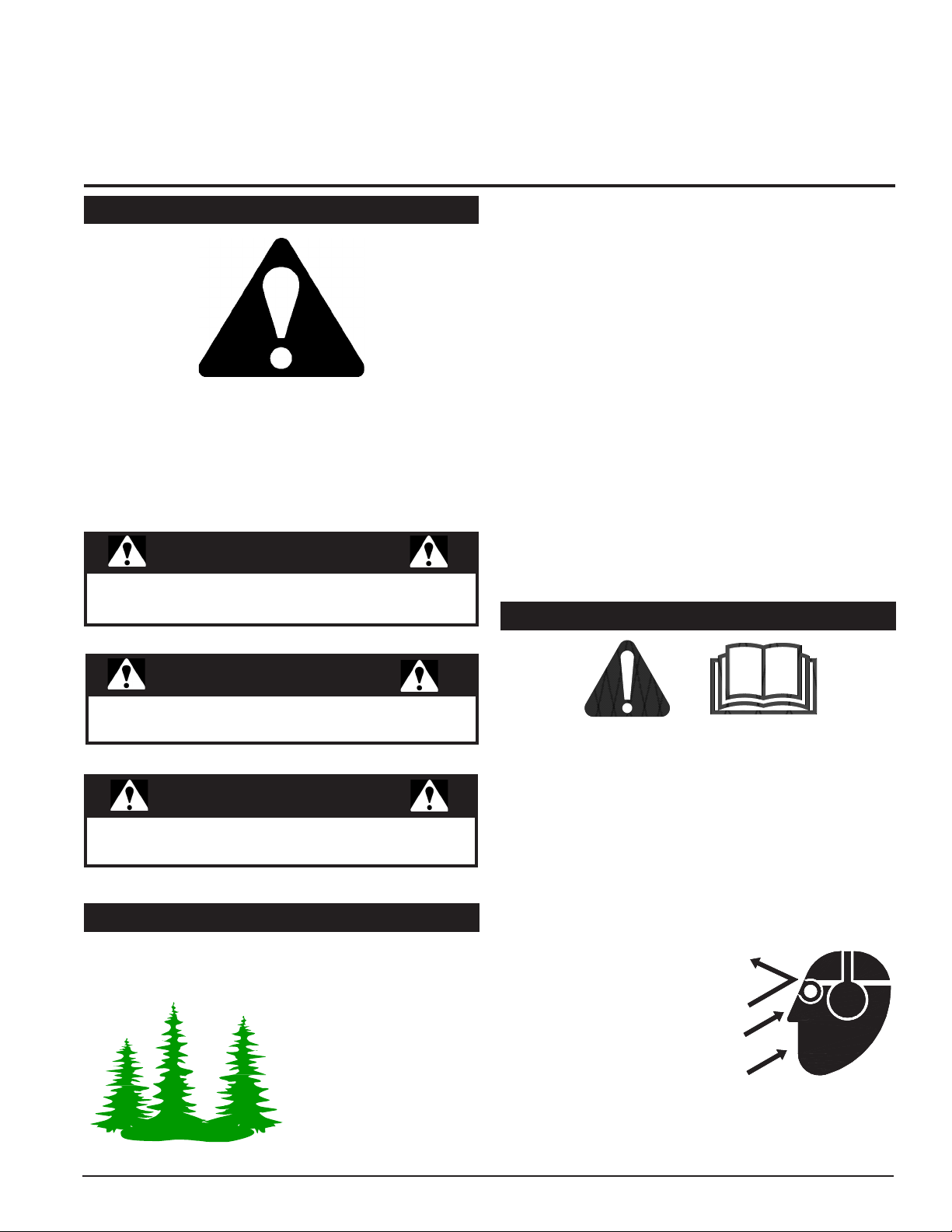
1.1 SAFETY ALERT
The Owner/Operator’s manual uses this symbol to alert
you of potential hazards. Whenever you see this symbol,
read and obey the safety message that follows it. Failure
to obey the safety message could result in personal injury,
death or property damage.
DANGER
Indicates an imminently hazardous situation that, if not
avoided, will result in death or serious injury.
The engine on your power equipment, like most outdoor
power equipment, is an internal combustion engine that
burns gasoline or diesel fuel (hydrocarbons). Therefore,
your power equipment must be equipped with a spark
arrester mufer in continuous effective working order. The
spark arrester must be attached to the engine exhaust
system in such a manner that ames or heat from the
system will not ignite ammable material.
Failure of the owner/operator of the equipment to comply
with this regulation is a misdemeanor under California law
and may also be a violation of other state and/or federal
regulations, laws, ordinances, or codes. Contact your
local re marshal or forest service for specic information
about which regulations apply in your area.
The standard mufer installed on the engine is not equipped
with a spark arrester. One must be added before using
this machine in an area where a spark arrester is required
by law. Contact the local authorities if these laws apply to
you. See your authorized engine dealer for spark arrester
options.
1.3 BEFORE OPERATING
ENGLISH
WARNING
Indicates a potentially hazardous situation that, if
not avoided, could result in death or serious injury.
CAUTION
Indicates a potentially hazardous situation that, if not
avoided, may result in minor or moderate injury.
1.2 EMISSION INFORMATION
Under California Law and the laws of several other states,
you are not permitted to operate an internal combustion
engine using hydrocarbon
fuels on any forest covered,
brush covered or grass
covered land or on land
covered with grain, hay or
other ammable agricultural
crops, without an engine
spark arrester in continuous
effective working order.
1. Read and understand this owner’s manual. Be
completely familiar with the controls and the proper
use of this equipment.
2. Familiarize yourself with all of the safety and operating
decals on this equipment and on any of its attachments
or accessories.
3. Keep safety decals clean and legible. Replace missing
or illegible safety decals.
4. Obtain and wear safety glasses and use hearing
protection at all times when operating this machine.
5. Avoid wearing loose fitted
clothing. Never operate this
machine while wearing clothing
with drawstrings that could
wrap around or get caught in
the machine.
6. Do not operate this machine
if you are under the influence
of alcohol, medications, or substances that can affect
your vision, balance or judgement. Do not operate if
tired or ill. You must be in good health to operate this
machine safely.
2 INCH CHIPPER/SHREDDER
1
Page 6

SAFETY
7. Do not operate this equipment in the vicinity of
bystanders. Keep the area of operation clear of all
persons, particularly small children. It is recommended
that bystanders keep at least 50 feet (15 meters) away
from the area of operation.
8. Do not allow children to operate this equipment.
9. Use only in daylight or good artificial light.
10. Do not run this equipment in an enclosed area. Engine
exhaust contains carbon monoxide gas, a deadly
poison that is odorless, colorless and tasteless. Do not
operate this equipment in or near buildings, windows
or air conditioners.
11. Always use an approved fuel container. Do not remove
gas cap or add fuel when engine is running. Add fuel
to a cool engine only.
12. Do not fill fuel tank indoors. Keep open flames, sparks,
smoking materials and other sources of combustion
away from fuel.
13. Do not operate machine without shields in place.
Failure to do so may cause serious injury or death.
14. Keep all guards, deflectors, and shields in good working
condition.
15. Before inspecting or servicing any part of this machine,
shut off the machine and make sure all moving parts
have come to a complete stop. Disconnect the battery
and remove the ignition key where applicable.
16. Check that all screws, nuts, bolts, and other fasteners
are secured, tightened and in proper working condition
before starting the machine.
17. Do not transport or move machine while it is operating
or running.
6. Shut off the machine and make sure all moving parts
have come to a complete stop before inspecting or
servicing any part of the machine. Disconnect the
battery and remove the ignition key if applicable.
7. Do not insert branches with a diameter larger than the
max chipper capacity into machine or machine damage
may occur.
8. When feeding material into machine, do not allow metal,
rocks, bottles, cans or any other foreign material to be
fed into the machine.
9. Ensure debris does not blow into traffic, parked cars,
or pedestrians.
10. Keep the machine clear of debris and other
accumulations.
11. Do not allow processed material to build up in the
discharge area. This may prevent proper discharge
and can result in kickback of material through the feed
opening.
12. If the machine becomes clogged, the cutting mechanism
strikes any foreign object, or the machine starts
vibrating or making an unusual noise, shut off machine
immediately and make sure all moving parts have come
to a complete stop. Disconnect the battery and remove
the ignition key if applicable. After the machine stops: A)
Inspect for damage, B) Replace or repair any damaged
parts, and C) Check for and tighten any loose parts.
13. On electric start models, disconnect cables from battery
before doing any inspection or service. Remove key.
14. Check blade bolts for proper torque after every 8 hours
of operation. Check blades and rotate or resharpen
daily or as required to keep blades sharp. Failure to do
so may cause poor performance, damage or personal
injury and will void the machine warranty.
1.4 OPERATION SAFETY
1. Always stand clear of discharge area when operating
this machine. Keep face and body away from feed
and discharge openings.
2. Keep hands and feet out of feed and discharge openings
while machine is operating to
avoid serious personal injury.
Stop and allow machine to come
to a complete stop before clearing
obstructions.
3. Set up your work site so you
are not endangering traffic and
the public. Take great care to provide adequate
warnings.
4. Do not climb on machine when operating. Keep proper
balance and footing at all times.
5. Check cutting chamber to verify it is empty before
starting the machine.
2
2 INCH CHIPPER/SHREDDER
1.5 MAINTENANCE & STORAGE SAFETY
1. Before inspecting, servicing, storing, or changing
an accessory, shut off the machine and make sure
all moving parts have come to a complete stop.
Disconnect the battery and remove the ignition key
where applicable.
2. Replace any missing or unreadable safety decals.
Refer to the safety decal section for part numbers.
3. Allow machine to cool before storing in an enclosure.
4. Store the machine out of reach of children and where
fuel vapors will not reach an open flame or spark.
5. Never store this machine with fuel in the fuel tank
inside a building where fumes may be ignited by an
open flame or spark. Ignition sources can be hot water
and space heaters, furnaces, clothes dryers, stoves,
electric motors, etc.
6. Drain the fuel and dispose of it in a safe manner for
storage periods of three months or more.
Page 7
SAFETY
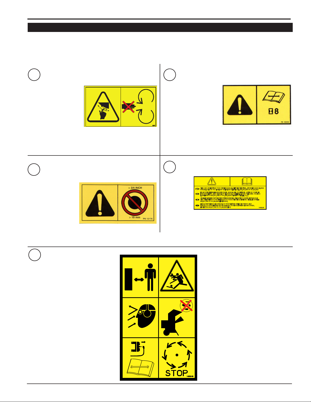
1.6 SAFETY DECALS
See Section 1.7 for decal locations. Familiarize yourself with all of the safety and operating decals on the machine
and the associated hazards. See the engine owner’s manual or contact the engine manufacturer for engine safety
instructions and decals. Make certain that all safety and operational decals on this machine are kept clean and in good
condition. Decals that need replacement must be applied to their original locations.
ENGLISH
P/N 12175
1
KEEP HANDS AND FEET
OUT OF INLET AND DISCHARGE OPENINGS
WHILE MACHINE IS
OPERATING TO AVOID
SERIOUS PERSONAL
INJURY. STOP AND
ALLOW MACHINE
TO COME TO A COMPLETE STOP BEFORE CLEARING
OBSTRUCTIONS.
P/N 12176
2
DO NOT INSERT
BRANCHES LARGER
THAN 3/4 INCH INTO
SHREDDER OR MACHINE DAMAGE MAY
OCCUR.
3
CHECK BLADE BOLTS
FOR PROPER TORQUE
AFTER EVERY 8 HOURS
OF OPERATION. CHECK
BLADES AND ROTATE
OR RESHARPEN DAILY
OR AS REQUIRED TO
KEEP BLADES SHARP.
REFER TO OWNERS MANUAL FOR INSTRUCTIONS. FAILURE
TO DO SO MAY CAUSE POOR PERFORMANCE, DAMAGE
OR PERSONAL INJURY AND WILL VOID THE MACHINE
WARRANTY.
4
READ AND UNDERSTAND YOU OWNERS MANUAL
BEFORE OPERATING. IF OWNERS MANUAL WAS
NOT INCLUDED OR YOU HAVE ANY QUESTIONS,
PLEASE CALL 800.247.7335 OR 701.282.5520
(U.S.A.)
P/N 12250
P/N 14942-00
P/N 14965-00
5
DO NOT OPERATE THIS EQUIPMENT
IN THE VICINITY OF BYSTANDERS. DO
NOT ALLOW CHILDREN TO OPERATE
THIS EQUIPMENT.
OBTAIN AND WEAR SAFETY GLASSES
AND USE HEARING PROTECTION AT ALL
TIMES WHEN OPERATING THIS MACHINE.
BEFORE INSPECTING OR SERVICING ANY PART OF THIS MACHINE, SHUT OFF POWER SOURCE,
DISCONNECT SPARK PLUG WIRE
FROM SPARK PLUG AND MAKE SURE
ALL MOVING PARTS HAVE COME TO A
COMPLETE STOP.
2 INCH CHIPPER/SHREDDER
ALWAYS STAND CLEAR OF
DISCHARGE AREA WHEN OPERATING
THIS MACHINE. KEEP FACE AND BODY
AWAY FROM FEED AND DISCHARGE
OPENINGS.
WHEN FEEDING SHREDDABLE
MATERIAL INTO CHIPPER, DO NOT
ALLOW METAL, ROCKS, BOTTLES,
CANS OR ANY OTHER FOREIGN
MATERIAL TO BE FED INTO CHIPPER
OR SHREDDER.
BEFORE INSPECTING OR SERVICING
ANY PART OF THIS MACHINE, SHUT
OFF POWER SOURCE, DISCONNECT
SPARK PLUG WIRE FROM SPARK PLUG
AND MAKE SURE ALL MOVING PARTS
HAVE COME TO A COMPLETE STOP.
3
Page 8

SAFETY
1.7 SAFETY DECAL LOCATIONS
The numbers below correspond to the decals in Section 1.6. Familiarize yourself with all of the safety and operational
decals on the machine and the associated hazards. See the engine owner’s manual or contact the engine manufacturer
for engine safety instructions and decals. Make certain that all safety and operating decals on this machine are kept
clean and in good condition. Decals that need replacement must be applied to their original locations.
2
4
5
1
1.8 INSTALLATION OF CHIPPER CHUTE BOLTS FOR CE COMPLIANT OPERATION
CE COMPLIANT OPERATION OF THIS MACHINE WILL
REQUIRE THE INSTALLATION OF THE TWO 5/16 X 3”
BOLTS WITH 5/16 WASHERS AND NYLOCK NUTS. CE
COMPLIANT AREA MACHINES WILL HAVE THE DECAL
SEEN BELOW.
BOLT, 5/16 x 3”
CE COMPLIANT
NUT, 5/16 NYLOCK
WASHER, 5/16
3
4
2 INCH CHIPPER/SHREDDER
Page 9

2
ASSEMBLY
Section
2.1 ATTACH WHEELS & AXLE
ENGLISH
2.3 FILL THE TANK
Attach wheels to the axle with two 5/8 X 3 1/4" bolts and
5/8" washers. Bolt the axle on to the chipper body with
four 5/16" X 1 3/4" carriage bolts and ange nuts.
BOLT, 5/8 X 3-1/4 HEX
BOLT, 5/16 X
1-3/4 CRG
WASHER, 5/8 FLAT
Figure 2.1
WASHER, 5/16 FLAT
NUT, 5/16 NYLOCK
2.2 HOPPER ATTACHMENT
Place hopper assembly on machine (as shown in Figure
2.2) and secure with six 5/16 x 3/4" serrated ange bolts
and 5/16 nuts.
Use only those types of fuels that are recommended in
your engine owner’s manual.
To add fuel:
1. Stop engine, wait for all parts to stop moving and
disconnect spark plug wire. Remove key from key
switch. Allow the engine and muffler to cool for at least
three minutes.
2. Clean area around fuel fill cap and remove cap.
3. Using a clean funnel, fill fuel tank to 1/2” below bottom
of filler neck to provide space for any fuel expansion.
Install fuel fill cap securely and wipe up any spilled
gasoline.
WARNING
Gasoline and diesel fuels are highly
ammable and their vapors are explosive. To
prevent personal injury or property damage:
Store fuel only in approved containers, in
well ventilated, unoccupied buildings, away
from sparks or ames. A container with a capacity of 2
gallons or less with a pouring spout is recommended.
Do not ll the fuel tank while the engine is hot or running,
since spilled fuel could ignite if it comes in contact with
hot parts or sparks from ignition. Do not start the engine
near spilled fuel. Never use fuel as a cleaning agent.
DO NOT MIX OIL WITH FUEL.
BOULON, 5/16 X 3/4 PO.
ECROU, 5/16
Figure 2.2
2.4 CHECK/ADD MOTOR OIL
Check the oil level and if needed ll the engine crankcase
with the type and amount of oil specied in the engine
owners manual.
2 INCH CHIPPER/SHREDDER
5
Page 10

3
FEATURES & CONTROLS
Section
Understanding how your machine works will help you achieve the best results when using your chipper/shredder. The
following descriptions dene the features and controls of your machine.
1. CHIPPER CHUTE
Feed branches no larger than 2 inches in diameter into the
chipper chute.
2. DISCHARGE CHUTE
Chipped and shredded materials are discharged onto the
ground through the discharge chute.
3. GAS TANK CAP
Check the gas level before each use.
4. OIL DIPSTICK
Check the oil level before each use by removing the dipstick.
5. RECOIL STARTER
Used to start engine. Grasp handle and pull out to start.
Refer to engine manual for further engine operating
instructions.
6. SHREDDER CHUTE
Feed sticks and branches no larger than ¾ inch in diameter
into the shredder chute.
7. TRANSPORT HANDLE
Used to move machine. Grasp handle, tip machine back
onto its wheels and push or pull machine to desired location.
Never transport or move machine with engine running.
6
7
3
1
4
5
2
6
2 INCH CHIPPER/SHREDDER
Page 11

4
Section
OPERATION
As with any other piece of outdoor power equipment, getting the feel for how your machine operates and getting to
know the best techniques for particular jobs are important
to overall good performance.
CHIPPING OPERATION
Feed materials to be chipped into the smaller, side chute.
Chipping materials should be no larger than 2" in diameter. The material is sliced into small chips and propelled
out through a discharge screen.
SHREDDING OPERATION
Feed material to be shredded into the larger, top chute.
Shredding materials should be no larger than 3/4" inch
in diameter. The material is shredded, and propelled out
through the discharge chute onto the ground.
4.1 STARTING THE MACHINE
Move the machine to a clear, level area outdoors before
starting. Do not operate in the vicinity of bystanders. Make
sure the cutting chamber is empty before starting.
ENGLISH
Figure. 4.1, Choke control lever and Fuel shut-off valve
1. Check engine oil level before starting.
2. Turn the fuel shut-off valve to the ON position.
3. Move the choke control lever to the CHOKE position.
4. Move the throttle control lever to the FAST position.
5. Pull the recoil starter until the engine starts. Make sure
the starting cord retracts.
6. For a Cold Engine: Gradually return the choke
control to the off position after the engine starts and
warms up. The machine may be operated during the
warm up period, but it may be necessary to leave
the choke partially on until the engine warms up.
For a Warm Engine: Return choke to the off position
as soon as engine starts.
WARNING
Before operating your machine, be sure you read and
understand all safety, controls and operating instructions in this Owner/Operators manual and on your machine. Failure to follow these instructions can result in
serious injury or property damage.
WARNING
WARNING
Move machine to a clear, level area outdoors before
starting. Do not operate in the vicinity of bystanders.
Make sure cutting chamber is empty before starting.
4.2 STOPPING THE MACHINE
1. Move the throttle control lever to SLOW position.
2. Allow the engine to run at idle for 30-60 seconds.
3. Stop the engine by moving the throttle to the STOP
position.
4. Turn the fuel shut-off valve to the OFF position.
5. Allow machine to come to a complete stop.
2 INCH CHIPPER/SHREDDER
7
Page 12

OPERATION
2. Limbs fed in to the chipper chute must be 2 inches
(5 cm) in diameter or less. Trim side branches that
cannot be bent enough to feed into the chipper chute.
Hold small diameter branches together in a bundle and
feed in simultaneously.
3. Material fed into the shredder chute must be ¾
inches (2 cm) in diameter or less. Common shredding
materials include grass, leaves, garden refuse, sticks,
and small branches.
Figure. 4.2, Throttle control lever
4.3 OPERATION
WARNING
Read and follow all safety instructions in this manual.
Failure to operate the machine in accordance with
the safety instructions MAY RESULT IN PERSONAL
INJURY!
CAUTION
Obtain and wear safety glasses at all times when
operating the machine.
Do not wear loose fitting clothing.
The operator should always wear heavy boots, gloves,
pants and a long-sleeved shirt.
Use common sense and practice safety to protect
yourself from branches, sharp objects, and other
harmful objects.
WARNING
DO NOT INSERT BRANCHES LARGER
THAN 3/4 INCH INTO SHREDDER OR
MACHINE DAMAGE MAY OCCUR.
4. Exclude pieces of metal, rocks, bottles, cans, and
other foreign objects when feeding material into the
machine.
5. Feed brush from the side of the chipper chute, rather
than from the front. Step aside to avoid being hit by the
brush moving into the chipper.
6. Place limb, butt end first, into the chipper chute
until it contacts the chipper blades. The actual feed
rate of the limb into the chipper will depend on the type
of material fed and sharpness of the cutting blades.
7. If the engine slows to where it may stall, stop feeding
material and allow the engine to recover. Feed material
more evenly.
WARNING
Never lean over the chipper chute to push objects
into the cutting device. Use a push stick or brush
paddle.
Never use shovels or forks to feed brush. They can
cause extensive damage if they contact the blades.
In addition, metal pieces can be ejected from the
chipper chute and cause serious injury or death.
Never feed brush into the chute with your feet.
Never use hands or feet to clear materials that build up in
the chute.
The machine chips and shreds a variety of materials into
a more readily decomposed or handled condition. The
following guidelines will help you get started.
1. Run unit at full operating speed before starting to
chip material.
8
2 INCH CHIPPER/SHREDDER
8. If the chipper jams, remove the branch and rotate it
before reinserting it into the chute. Alternately insert
and retract the limb or insert continuously at a rate that
will not kill the engine.
9. Do not use the clutch to clear a plugged rotor. This
may cause belt damage. Refer to the instructions for
clearing a plugged rotor in the Service and Maintenance
section.
10. Alternate greener material with dry material to
lubricate the chipping blades for longer life and better
performance. Chipping dead, dry material will create
heat and dull the chipping blades quickly.
11. Sharpen the chipping blades periodically. Check
the sharpness of the blades every 5-15 hours. Refer
to the Service and Maintenance section for sharpening
instructions.
Page 13

5
SERVICE & MAINTENANCE
Section
5.1 MAINTENANCE SCHEDULE
The items listed in this service and maintenance schedule are to be checked, and if necessary, corrective action taken.
This schedule is designed for units operating under normal conditions. If the unit is operating in adverse or severe
conditions, it may be necessary for the items to be checked and serviced more frequently.
SEE ENGINE OWNER’S MANUAL FOR FURTHER ENGINE MAINTENANCE AND TROUBLESHOOTING
INFORMATION.
SERVICE AND MAINTENANCE SCHEDULE
FREQUENCY
ENGLISH
COMPONENT
AIR CLEANER CHECK AND CLEAN (1)
ENGINE OIL CHANGE (1)
SPARK PLUG CHECK CONDITION AND GAP
ENGINE OIL CHECK/FILL
FUEL TANK CHECK/FILL
ALL INTERNAL AND EXTERNAL
NUTS AND BOLTS
CHIPPER BLADES
SHREDDER KNIVES CHECK CONDITION
ENTIRE MACHINE CLEAN
(1) PERFORM MORE FREQUENTLY UNDER EXTREMELY DUSTY CONDITIONS.
(2) PERFORM MORE FREQUENTLY WHEN CHIPPING DRY OR DIRTY WOOD.
As the Limited Warranty states, failure by the Owner to perform normal maintenance will void the machine’s
warranty. The aggressive, high-speed nature of chipping REQUIRES THE OWNER TO PERFORM THE ABOVE
LISTED NORMAL MAINTENANCE. Special consideration to maintain and re-torque the CHIPPER ANVIL, CHIPPER
BLADES, AND ALL INTERNAL AND EXTERNAL NUTS AND BOLTS is the sole responsibility of the Owner. Failure
by the Owner to do so shall be cause for denial of warranty.
MAINTENANCE
REQUIRED
CHECK TIGHTNESS
CHECK SHARPNESS AND RETORQUE TO 25 FT-LBS (2)
REFER TO ENGINE
OPERATOR’S MANUAL
BEFORE
EACH USE
EVERY 8
HOURS
5.2 CHIPPER BLADE MAINTENANCE
WARNING
Do not tip the machine all the way over on its side when
servicing.
WARNING
The chipping blades are sharp! Use care when working
on the machine to avoid injury.
2 INCH CHIPPER/SHREDDER
The chipper blades will eventually become dull, making
chipping difcult and adding extra strain on the machine.
CHECK THE SHARPNESS OF THE BLADES EVERY
5 - 15 HOURS OF OPERATION AND SHARPEN AS
NEEDED.
Your blades need to be sharpened if:
• Machine vibrates severely when material is fed into the
chipper.
• Small diameter branches do not self-feed.
• Chips discharge unevenly or have stringy tails,
especially when chipping green branches.
9
Page 14

SERVICE & MAINTENANCE
NICK GREATER
BEFORE INSPECTING OR SERVICING ANY PART OF THIS MACHINE, SHUT OFF POWER SOURCE,
AND MAKE SURE ALL MOVING PARTS HAVE COME TO A COMPLETE STOP.
WARNING
Before you sharpen the chipping blades, check for
permanent damage. Replace the blade if:
• There are cracks, broken corners or nicks greater than
1/8" (see below).
CRACK
GREATER
THAN 1/8”
BROKEN
CORNER
THAN 1/8”
• The base of the cutting edge is worn or has been resharpened so that it no longer extends past the chipping
slot (see below).
CHIPPER
DISC
NEW
BLADE
CHIPPING
SLOT
CHIPPER
DISC
BLADE IS
TOO SHORT,
MUST BE
REPLACED
CHIPPING
SLOT
6. Small imperfections such as nicks and burrs on the flat
side of the blade will not affect the chipping performance
of the machine.
7. For blades that have been repeatedly sharpened,
ensure that the sharpened surface extends past the
chipping slot opening. If it does not extend past the
opening, the blades should be replaced.
MOUNTING SURFACE
45°
.25
(DO NOT GRIND)
SHARPENED
SURFACE
Figure. 5.1, Double-Edged parallel blade
MOUNTING SURFACE
(DO NOT GRIND)
SHARPENED
SURFACE
WARNING
Before inspecting or servicing any part of this machine,
shut off power source, remove key, disconnect the
battery cables and make sure all moving parts have
come to a complete stop.
5.4 REMOVING THE CHIPPER BLADES
5.3 SHARPENING THE BLADES
The blades can be ground on a bench grinder or by a
professional.
1. Never sharpen or grind the mounting surfaces of the
blades. This will cause the edge to roll and the blade will
be damaged, resulting in poor chipping performance.
2. Regrind the angled edge of the chipping blades to 45
degrees (Figure 5.1). Make sure some type of fixture is
used to correctly hold the blade at the proper angle.
3. Be careful when grinding so that the blade does not
become overheated and change color. This will remove
the heat-treated properties.
4. Use short grinding times and cool with water or some
type of liquid coolant.
5. Remove an equal amount off each blade to maintain
rotor balance.
PLACE A LONG BOLT OR PUNCH IN HOLE ON ENGINE
SIDE HOUSING PANEL. ALIGN WITH HOLE IN ROTOR TO
PREVENT IT FROM TURNING WHILE SERVICING. SEE
FIGURE 5.2
Figure. 5.2, Illustration shown with chipper chute removed to show rotor
lock hole location
10
2 INCH CHIPPER/SHREDDER
Page 15

WARNING
BEFORE INSPECTING OR SERVICING ANY PART OF THIS MACHINE, SHUT OFF POWER SOURCE,
AND MAKE SURE ALL MOVING PARTS HAVE COME TO A COMPLETE STOP.
CHIPPER BLADE REMOVAL
1. Remove the six 5/16” spiral lock nuts securing the front
panel to the housing.
2. Remove the two 5/16-18 x 5/8” bolts and securing the
blade to the rotor. Note the relation of blade cutting
edge to rotor.
SERVICE & MAINTENANCE
ENGLISH
Figure. 5.4, Examples of damage to knives
5.6 REMOVING THE SHREDDING KNIVES
NOTE
Never reuse the #10-24 bolts, nuts or shafts. Always install
new parts when replacing knives or blades.
Figure 5.3, Removing the chipper blades
3. Inspect blade to see if cracks or nicks are visible. If
cracks are present, the blade cannot be re-sharpened
and must be discarded. (For service, order small blade
replacement kit #70738.)
4. If both sides of the blade have not been used yet, the
blade can be rotated so the new edge is in position
and re-used.
5. If both sides of the blade have been used, it must be
re-sharpened. The blades can be ground on a bench
grinder or by a professional.
6. Replace blade on the rotor. Note correct orientation of
cutting edge to rotor.
7. Apply thread locking adhesive to bolts and torque to
25 ft-lbs.
8. Repeat steps 2-7 for second blade.
9. Replace front cover and six 5/16 nuts. Test machine.
To replace damaged shredder knives or spacers, order
Shredder Knife Kit, 77616-00.
1. Remove the six 5/16” spiral lock nuts securing the front
panel to the housing.
2. Working one shaft at a time, remove the #10-24 screw
and nut securing the spacer.
3. Note the knife and spacer configuration as it must
be duplicated when assembling the new knives and
spacers.
5.5 SHREDDER KNIVES MAINTENANCE
Do not attempt to sharpen shredder knives. Inspect the
knives often for signs of damage.
If a knife has any sign of cracking or is broken in any way,
it should be replaced immediately. (For service order,
Shredder Knife Kit, 77616-00.)
2 INCH CHIPPER/SHREDDER
Figure. 5.5, Shaft assembly hole location
11
Page 16

SERVICE & MAINTENANCE
BEFORE INSPECTING OR SERVICING ANY PART OF THIS MACHINE, SHUT OFF POWER SOURCE,
AND MAKE SURE ALL MOVING PARTS HAVE COME TO A COMPLETE STOP.
WARNING
4. Push shaft through the rotor and remove it along with
old spacers and knives.
5. Insert new shaft into same hole location on rotor and
assemble the new knives and spacers as they were
previously.
6. Secure with #10-24 screw and nut in spacer and torque
to 33 in-lbs.
7. Repeat on second shaft.
8. Replace front cover and six 5/16 nuts.
5.8 REMOVING THE ROTOR
1. Remove the front housing panel by removing the six
5/16 spiral lock nuts.
2. The rotor is connected directly to the engine crankshaft.
If the rotor needs servicing, remove the 5/16 x 2-1/2"
bolt, 5/16" spring washer and the two 1/4 x 1/2" set
screws and key securing it to the crankshaft.
3. Pull the rotor assembly off the crankshaft.
4. Reverse the procedure to install the rotor. Torque 5/1624 x 2-1/2" bolt to 25 ft. lbs.
5.9 CHANGING THE DISCHARGE SCREEN
There is one optional discharge screen available with a
smaller mesh that will produce smaller-sized shredded
product. Order part #76893-35 for this screen. To change
the discharge screen, proceed as follows:
1. Remove the two 5/16" nuts and 5" bolts securing the
discharge screen and pull the discharge screen out
from the bottom.
2. Clean any trash or debris from the screen area.
Figure. 5.6, Knives and spacers conguration
The SC2170 has the option of additional knives being
added to the rotor. Order Additional Knives Kit, 77618-00
and follow the complete installation instructions.
5.7 CLEARING A PLUGGED ROTOR
If too much material is fed into the chipper/shredder or
if the material is too large, the machine may become
plugged. To clear a plugged rotor, proceed as follows:
1. Turn off the machine and let all moving parts come to
a complete stop.
2. Remove left nut and bolt holding the discharge screen
in place (see Fig. 5.7).
3. Reach up into the discharge chute and pivot that side
of the discharge screen down.
4. Clean any trash or debris from the screen area, being
careful not to touch the sharp blades.
5. Pivot the screen back up to its original position.
6. Secure with the 5/16" nut and 5-1/2" bolt
3. Insert the replacement screen into the bottom of the
chipper body.
4. Secure with two 5/16 x 5" bolts and 5/16" nuts.
Figure. 5.7, Removing the discharge screen
12
2 INCH CHIPPER/SHREDDER
Page 17

6
TROUBLESHOOTING
Section
Before performing any of the corrections in this troubleshooting chart, refer to the appropriate information contained in
this manual for the correct safety precautions and operating or maintenance procedures. Contact your dealer or the
factory for service problems with the machine.
PROBLEM POSSIBLE CAUSES REMEDY
Improper control settings. Use proper settings.
Lack of fuel. Fill fuel tank.
Engine will not start.
Engine or rotor stalls or
stops.
Chipper does not chip.
Engine overheats.
Hard to feed chipper;
requires excessive power
to chip.
Shredder requires
excessive power or stalls.
Engine stalls or belt squeals
when engaging clutch.
Material from chipper wraps
around rotor shaft
Excessive vibration while
running.
Rotor will not turn.
Spark plug disconnected. Connect spark plug.
Dirty, stale or contaminated gas. Refill gas tank with fresh, clean unleaded regular gasoline.
Internal engine problems. See your dealer.
Obstructed discharge. Use branch or similar object to clear discharge.
Plugged rotor. Clear rotor. Feed material more evenly.
Feeding material that is too
large.
Dull chipper blades. Rotate or sharpen blades.
Drive belts loose or worn. Inspect drive belts, adjust or replace if needed.
Attempting to feed branches that
are too large.
Broken or missing chipper
blades
Cooling system plugged. Clean cooling fan and fins.
Improper oil level. Fill engine to correct oil level. Refer to the engine owners manual.
Dull chipper blades. Reverse or sharpen blades.
Obstructed discharge. Use branch or similar object to clear discharge.
Improper blade clearance. Adjust clearance between chipper anvil and chipper blades.
Obstructed discharge. Use branch or similar object to clear discharge.
Plugged rotor. Clear rotor, feed material into shredder more evenly.
Wet or green material will not
discharge.
Engaging clutch too fast. Engage clutch more slowly.
Plugged rotor. Clear rotor. Feed material more evenly.
Belt tension too loose. Replace belt or spring.
Stringy, green material bypasses
chipper blades.
Dull chipper blades. Sharpen blades.
Improper blade clearance. Adjust clearance between anvil and chipper blades.
Drive system vibration. Check drive belts and pulleys for bad or worn areas. Check for dull chipper
Rotor out of balance. Inspect rotor for broken or missing chipper blades and shredder knives;
Chipper blade to anvil clearance
is incorrect.
Drive belt too loose or broken. Replace belt or spring.
Obstructed discharge. Use branch or similar object to clear discharge.
Plugged rotor. Clear rotor. Feed material more evenly.
Reduce size of material.
Limit branch size to 2 inches in diameter.
Replace blade.
Alternately feed dry material or install larger discharge screen.
Rotate branch or material when feeding to cut completely.
blades or shredder knives.
replace if needed. Check rotor to see if it wobbles. Check to see if
rotor is assembled correctly.
Set chipper blade/anvil clearance to recommended distance (1/16" to
1/8").
ENGLISH
2 INCH CHIPPER/SHREDDER
13
Page 18

7
SPECIFICATIONS
Section
SC2170
DESCRIPTION English Metric
OVERALL SIZE 29" x 23" x 50" 74cm x 58cm x 127cm
OVERALL WEIGHT 120 lbs. 54,5 kg
MAX CHIIPPER CAPACITY 2" 5.1 cm
CHIPPER BLADES 3.125" x 2" x .25" 8,0 cm x 5,1 cm x 0,64 cm
MAX SHREDDER CAPACITY 3/4" 2 cm
SHREDDER KNIVES
ROTOR SPEED 3,800 RPM
ROTOR SIZE 12.8" in diameter 32.6 cm de diamètre
ROTOR WEIGHT 15 lbs. 6,8 kg
WHEEL BASE 26" 66 cm
ENGINE 170cc Subaru
4 Standard
4 Optional
14
2 INCH CHIPPER/SHREDDER
Page 19

8
OPTIONS
Section
PART NUMBER DESCRIPTION
31605-00 HOUR/TACH KIT
70738 KIT, SMALL CHIPPER BLADE
76758-35 SCREEN, 1.13" STANDARD
76893-35 SCREEN, .75" FINE
77616-00 KIT, SHREDDER KNIVES
77618-00 KIT, ADDITIONAL KNIVES
ENGLISH
Shredder Knives Kit, 77616-00
Additional Knives Kit, 77618-00
.75" Fine Screen, 76893-35 1.13" Standard Screen, 76758-35
2 INCH CHIPPER/SHREDDER
Small Chipper Blade Kit, 70738
15
Page 20

SPECIFICATIONS
BOLT TORQUE
The tables below are for reference purposes only and their use by anyone is entirely voluntary, unless otherwise noted.
Reliance on their content for any purpose is at the sole risk of that person and any loss or damage resulting from the
use of this information is the responsibility of that person.
SAE
SAE - 2
SAE - 5
SAE - 8
BOLT DIAMETER
Grade
and
Head
A
Markings
ENGLISH
BOLT DIAMETER (A)
1/4” 7.5 5.5 11 8 16 12
5/16” 15 11 23 17 34 25
3/8” 27 20 41 30 61 45
7/16” 41 30 68 50 95 70
1/2” 68 50 102 75 149 11 0
9/16” 97 70 149 11 0 203 150
5/8” 122 90 203 150 312 230
3/4” 217 160 353 260 515 380
7/8” 230 170 542 400 814 600
1” 298 220 786 580 1220 900
1-1/8” 407 300 1085 800 1736 1280
1-1/4” 570 420 2631 1940 2468 1820
SAE 2 SAE 5 SAE 8
N.m Ft-lb. N.m Ft-lb. N.m Ft-lb.
BOLT TORQUE *
* Torque value for bolts and
capscrews are identified by their
head markings.
Torque figures indicated above are
valid for non-greased or non-oiled
threads and heads unless otherwise
specified. Therefore, do not grease
or oil bolts or capscrews unless
otherwise specified in this manual.
When using locking elements,
increase torque values by 5%.
METRIC
Grade
and
Head
Markings
4.8
4.8
8.8
8.8 10.9
10.9
12.9
12.9
BOLT DIAMETER
A
METRIC
BOLT DIAMETER
(A)
M3 0.5 0.4 - - - - - -
M4 3 2.2 - - - - - -
M5 5 4 - - - - - -
M6 6 4.5 11 8.5 17 12 19 14.5
M8 15 11 28 20 40 30 47 35
M10 29 21 55 40 80 60 95 70
M12 50 37 95 70 140 105 165 120
M14 80 60 150 110 225 165 260 190
M16 125 92 240 175 350 255 400 300
M18 175 125 330 250 475 350 560 410
M20 240 180 475 350 675 500 800 580
M22 330 250 650 475 925 675 1075 800
M24 425 310 825 600 1150 850 1350 1000
M27 625 450 1200 875 1700 1250 2000 1500
4.8 8.8 10.9 12.9
N.m Ft-lb. N.m Ft-lb. N.m Ft-lb. N.m Ft-lb.
BOLT TORQUE *
16
2 INCH CHIPPER/SHREDDER
Page 21

ECHO BEAR CAT
www.bearcatproducts.com
237 NW 12th Street, West Fargo, ND 58078-0849
Phone: 701.282.5520 • Toll Free: 888.625.4520 • Fax: 701.282.9522
E-mail: service@bearcatproducts.com • sales@bearcatproducts.com
 Loading...