

Page 1

LOG SPLITTER
LS27270 - HYDRAULIC LOG SPLITTER
LS27270T - TOWABLE HYDRAULIC LOG
SPLITTER
Rev. 103107
Manual P/N 36190-00
Companion to P/N 36191-00
SN/VIN RANGE : 0 - CURRENT
OWNER'S MANUAL
Page 2

Before You Begin
DEAR ECHO BEAR CAT CUSTOMER
Thank you for purchasing a ECHO Bear Cat product. The ECHO Bear Cat line is designed, tested, and manufactured
to give years of dependable performance. To keep your machine operating at peak effi ciency, it is necessary to adjust
it correctly and make regular inspections. The following pages will assist you in the operation and maintenance of your
machine. Please read and understand this manual before operating your machine.
If you have any questions or comments about this manual, please call us toll-free at 1-800-247-7335.
If you have any questions or problems with your machine, please call or write your local authorized ECHO Bear Cat Dealer.
This document is based on information available at the time of its publication. ECHO Bear Cat is continually making
improvements and developing new equipment. In doing so, we reserve the right to make changes or add improvements
to our product without obligation for equipment previously sold.
PLEASE SEND US YOUR WARRANTY CARD
A warranty card is included in your owner's kit packaged with your machine. Please take the time to fi ll in the information
requested on the card. When you send your completed card to us, we will register your machine and start your
coverage under our limited warranty.
FOR MACHINE SERVICE OR PARTS:
For service assistance, contact your nearest authorized
ECHO Bear Cat dealer or the factory. For parts, contact
your authorized dealer. Your dealer will need to know the
serial number of your machine to provide the most effi cient
service. See below for information on how to identify and
record the serial number for your machine.
FOR ENGINE SERVICE OR PARTS:
For engine service or parts, contact your nearest authorized
engine dealer. ECHO Bear Cat does not handle any parts,
repairs or warranties for engines.
IDENTIFICATION NUMBER LOCATION
Your machine will have either a serial number or vehicle
identifi cation number (VIN). VINs are located on the left
side of the trailer frame near the hitch. They are 17-digit
numbers of the format: 5VJAA001XXWXXXXX. Serial
numbers are located on the machine body. They are 6digit numbers.
Record your identifi cation number in the space provided
and on the warranty registration card.
ORDERING PARTS
Only genuine ECHO Bear Cat replacement parts should
be used to repair the machine. Replacement parts
manufactured by others could present safety hazards,
even though they may fi t on this machine. Replacement
parts are available from your ECHO Bear Cat dealer.
Provide the following when ordering parts:
The SERIAL NUMBER OR VIN of your machine.
The PART NUMBER of the part.
The PART DESCRIPTION.
The QUANTITY needed.
SERIAL NUMBER OR VIN
HOW TO CONTACT ECHO BEAR CAT
ADDRESS PHONE E-MAIL HOURS
237 NW 12th Street
P.O. Box 849
West Fargo, ND 58078
© 2006, CRARY INDUSTRIES, ALL RIGHTS RESERVED. PRODUCED AND PRINTED IN THE U.S.A.
800-247-7335
701-282-5520
FAX: 701-282-9522
opesales@crary.com
service@crary.com
Monday - Friday,
8 am to 5 pm
Central Time
Page 3

LIMITED WARRANTY
This warranty applies to all AG and Outdoor Power Equipment manufactured by Crary Industries.
Crary Industries warrants to the original owner each new Crary Industries product to be free from defects
in material and workmanship, under normal use and service. The warranty shall extend 1 year from date of
delivery for income producing (commercial) applications and 2 years from date of delivery for non-income
producing (consumer) use of the product. The product is warranted to the original owner as evidenced by a
completed warranty registration on fi le at Crary Industries. Replacement parts are warranted for (90) days
from date of installation.
THE WARRANTY REGISTRATION MUST BE COMPLETED AND RETURNED TO CRARY INDUSTRIES
WITHIN 10 DAYS OF DELIVERY OF THE PRODUCT TO THE ORIGINAL OWNER OR THE WARRANTY
WILL BE VOID.
In the event of a failure, return the product, at your cost, along with proof of purchase to the selling Crary
Industries dealer. Crary Industries will, at its option, repair or replace any parts found to be defective in
material or workmanship. Warranty on any repairs will not extend beyond the product warranty. Repair or
attempted repair by anyone other than a Crary Industries dealer as well as subsequent failure or damage
that may occur as a result of that work will not be paid under this warranty . Crary Industries does not warrant
replacement components not manufactured or sold by Crary Industries.
This warranty applies only to parts or components that are defective in material or workmanship.
This warranty does not cover normal wear items including but not limited to bearings, belts, pulleys, fi lters
and chipper knives.
This warranty does not cover normal maintenance, service or adjustments.
This warranty does not cover depreciation or damage due to misuse, negligence, accident or improper
maintenance.
This warranty does not cover damage due to improper setup, installation or adjustment.
This warranty does not cover damage due to unauthorized modifi cations of the product.
Engines are warranted by the respective engine manufacturer and are not covered by this warranty.
Crary Industries is not liable for any property damage, personal injury or death resulting from the unauthorized
modifi cation or alteration of a Crary product or from the owner’s failure to assemble, install, maintain or
operate the product in accordance with the provisions of the Owner’s manual.
Crary Industries is not liable for indirect, incidental or consequential damages or injuries including but not
limited to loss of crops, loss of profi ts, rental of substitute equipment or other commercial loss.
This warranty gives you specifi c legal rights. You may have other rights that may vary from area to area.
Crary Industries makes no warranties, representations or promises, expressed or implied as to the performance
of its products other than those set forth in this warranty. Neither the dealer nor any other person has any
authority to make any representations, warranties or promises on behalf of Crary Industries or to modify
the terms or limitations of this warranty in any way. Crary Industries, at its discretion, may periodically offer
limited, written enhancements to this warranty.
CRARY INDUSTRIES RESER VES THE RIGHT TO CHANGE THE DESIGN AND/OR SPECIFICA TIONS OF ITS
PRODUCTS AT ANY TIME WITHOUT OBLIGATION TO PREVIOUS PURCHASERS OF ITS PRODUCTS.
Page 4

TABLE OF CONTENTS
DESCRIPTION PAGE DESCRIPTION PAGE
SAFETY .........................................................................1
1.1 SAFETY ALERT SYMBOL ........................................ 1
1.2 BEFORE OPERATING .............................................. 1
1.3 OPERATION SAFETY ..............................................2
1.4 MAINTENANCE AND STORAGE SAFETY .............. 2
1.5 TOWING SAFETY ..................................................... 2
1.6 SAFETY DECAL LOCATIONS .................................. 4
1.7 SAFETY DECALS .................................................... 5
ASSEMBLY .................................................................... 6
2.1 INSTALL THE HYDRAULIC CYLINDER ...................6
2.2 ATTACH THE HITCH .................................................6
2.3 FILL THE TANK ......................................................... 7
FEATURES & CONTROLS ............................................8
3.1 LOG SPLITTER COMPONENTS .............................. 8
3.2 ENGINE COMPONENTS .......................................... 9
OPERA TION ................................................................10
4.1 STARTING THE LOG SPLITTER............................10
4.2 STOPPING THE LOG SPLITTER ........................... 10
4.3 OPERATING THE LOG SPLITTER ........................10
4.4 VERTICAL OPERATION ......................................... 12
4.5 STORAGE MODE ................................................... 12
SERVICE & MAINTENANCE .......................................13
5.1 MAINTENANCE SCHEDULE.................................. 13
5.2 LUBRICATION ........................................................14
5.3 FILLING HYDRAULIC FLUID.................................. 15
5.4 CHANGING HYDRAULIC OIL FILTER ................... 15
5.5 TRAILER SERVICE TIPS........................................15
TROUBLESHOOTING .................................................16
SPECIFICATIONS ........................................................17
7.1 MACHINE SPECIFICATIONS ................................. 17
7.2 BOLT TORQUE .......................................................18
iv LOG SPLITTER
Page 5
1
SAFETY
Section
1.1 SAFETY ALERT SYMBOL
The Owner/Operator’s manual uses this symbol to alert
you of potential hazards. Whenever you see this symbol,
read and obey the safety message that follows it. Failure
to obey the safety message could result in personal injury ,
death or property damage.
DANGER
Indicates an imminently hazardous situation that, if not
avoided, will result in death or serious injury.
WARNING
Indicates a potentially hazardous situation that, if not
avoided, could result in death or serious injury.
CAUTION
Indicates a potentially hazardous situation that, if not
avoided, may result in minor or moderate injury.
1.2 BEFORE OPERATING
Read and understand this owner’s manual. Be
1.
completely familiar with the controls and the proper
use of this equipment.
Familiarize yourself with all of the safety and operating
2.
decals on this equipment and on any of its attachments
or accessories.
Keep safety decals clean and legible. Replace missing
3.
or illegible safety decals.
Obtain and wear safety glasses and use hearing
4.
protection at all times when operating this machine.
Avoid wearing loose fitted clothing. Never operate this
5.
machine while wearing clothing with drawstrings that
could wrap around or get caught in the machine.
Do not operate this machine if you are under the
6.
influence of alcohol, medications, or substances that
can affect your vision, balance or judgement. Do not
operate if tired or ill. You must be in good health to
operate this machine safely.
Do not operate this equipment in the vicinity of
7.
bystanders. Keep the area of operation clear of all
persons, particularly small children. It is recommended
that bystanders keep at least 50 feet (15 meters) away
from the area of operation.
Do not allow children to operate this equipment.
8.
Use only in daylight or good artificial light.
9.
Do not run this equipment in an enclosed area. Engine
10.
exhaust contains carbon monoxide gas, a deadly
poison that is odorless, colorless and tasteless. Do not
operate this equipment in or near buildings, windows
or air conditioners.
Always use an approved fuel container. Do not remove
11.
gas cap or add fuel when engine is running. Add fuel
to a cool engine only.
Do not fill fuel tank indoors. Keep open flames, sparks,
12.
smoking materials and other sources of combustion
away from fuel.
Do not operate machine without shields in place.
13.
Failure to do so may cause serious injury or death.
Keep all guards, deflectors, and shields in good working
14.
condition.
Before inspecting or servicing any part of this machine,
15.
shut off the machine and make sure all moving parts
have come to a complete stop. Disconnect the spark
plug.
Check that all screws, nuts, bolts, and other fasteners
16.
are secured, tightened and in proper working condition
before starting the machine.
Do not transport or move machine while it is operating
17.
or running.
1LOG SPLITTER
Page 6

SAFETY
1.3 OPERATION SAFETY
Always stand clear of discharge area when operating
1.
this machine. Keep face and body away from cutting
area.
Keep hands and feet out of cutting
2.
area while machine is operating
to avoid serious personal injury.
Stop and allow machine to come
to a complete stop before clearing
obstructions.
Set up your work site so you are
3.
not endangering traffic and the public. Take great care
to provide adequate warnings.
Do not climb on machine when operating. Keep proper
4.
balance and footing at all times.
Ensure the control lever is in the neutral detent position
5.
before starting the machine.
Keep the machine clear of debris and other
6.
accumulations.
Do not attempt to split two logs with one positioned on
7.
top of the other.
Check the logs before splitting. Ensure there are no
8.
foreign materials, such as nails, present in the wood.
Do not attempt to split wood across the grain.
9.
Do not load the log splitter while the splitting wedge
10.
is moving.
Hold the log by the sides when you are positioning it
11.
into the log splitter. Do not hold the log by the ends.
Block the wheels of the log splitter before operating.
12.
Do not step across the log splitter while the engine is
13.
running.
Do not operate the log splitter while it is attached to a
14.
towing vehicle.
Drain the fuel and dispose of it in a safe manner for
6.
storage periods of three months or more.
Replace any worn, cut, abraded, flattened or crimped
7.
hydraulic hoses.
Wear proper hand and eye protection when searching
8.
for a hydraulic leak. Instead of using your hands, use
a piece of wood or cardboard as a backstop to identify
a leak.
1.5 TOWING SAFETY
Ensure the log splitter is locked in the horizontal position
1.
before towing.
Connect hitch safety chains. Tighten trailer hitch bolts.
2.
Do not attempt to tow the trailer if the vehicle is not
equipped with a 2” (50 mm) ball.
Do not exceed the maximum towing speed indicated
3.
on tire sidewall. Inflate tires to manufacturer’s
specifications as stated on the tire sidewall.
Optimum towing performance can be achieved by
4.
maintaining a horizontal trailer hitch.
Check wheel lug bolts periodically to ensure they are
5.
tight and secure.
Make sure the jack stand on the trailer is in the UP
6.
position during towing. Place the jack stand on a level
surface and secure it in the DOWN position before
using.
Never allow passengers to ride on the machine.
7.
Shut off fuel supply when towing.
8.
Towing laws may vary in different countries/regions/
9.
states. It is recommended that you contact your local
motor vehicle department for any special regulations
that pertain to towing and know the laws of any country/
region/state you travel through.
Do not tow machine faster than 45 mph (72 kph).
10.
1.4 MAINTENANCE AND STORAGE SAFETY
Before inspecting, servicing, storing, or changing an
1.
accessory, shut off the machine and make sure all
moving parts have come to a complete stop. Disconnect
the spark plug.
Replace any missing or unreadable safety decals.
2.
Refer to the safety decal section for part numbers.
Allow machine to cool before storing in an enclosure.
3.
Store the machine out of reach of children and where
4.
fuel vapors will not reach an open flame or spark.
Never store this machine with fuel in the fuel tank
5.
inside a building where fumes may be ignited by an
open flame or spark. Ignition sources can be hot water
and space heaters, furnaces, clothes dryers, stoves,
electric motors, etc.
2 LOG SPLITTER
Page 7

SAFETY
THIS PAGE LEFT INTENTIONALLY BLANK
3LOG SPLITTER
Page 8
SAFETY
1.6 SAFETY DECAL LOCATIONS
The numbers below correspond to the decals in Section 1.7. Familiarize yourself with all of the safety and operational
decals on the machine and the associated hazards. See the engine owner’s manual or contact the engine manufacturer
for engine safety instructions and decals. Make certain that all safety and operating decals on this machine are kept
clean and in good condition. Decals that need replacement must be applied to their original locations.
*NOTE: DECAL #1 IS LOCATED IN TWO PLACES ON THE
MACHINE. ONE IS LOCATED ON THE OUTSIDE OF THE
DRIVE SHAFT SHIELD. THE OTHER IS LOCATED ON THE
INSIDE OF THE DRIVE SHAFT SHIELD.
4 LOG SPLITTER
Page 9
SAFETY
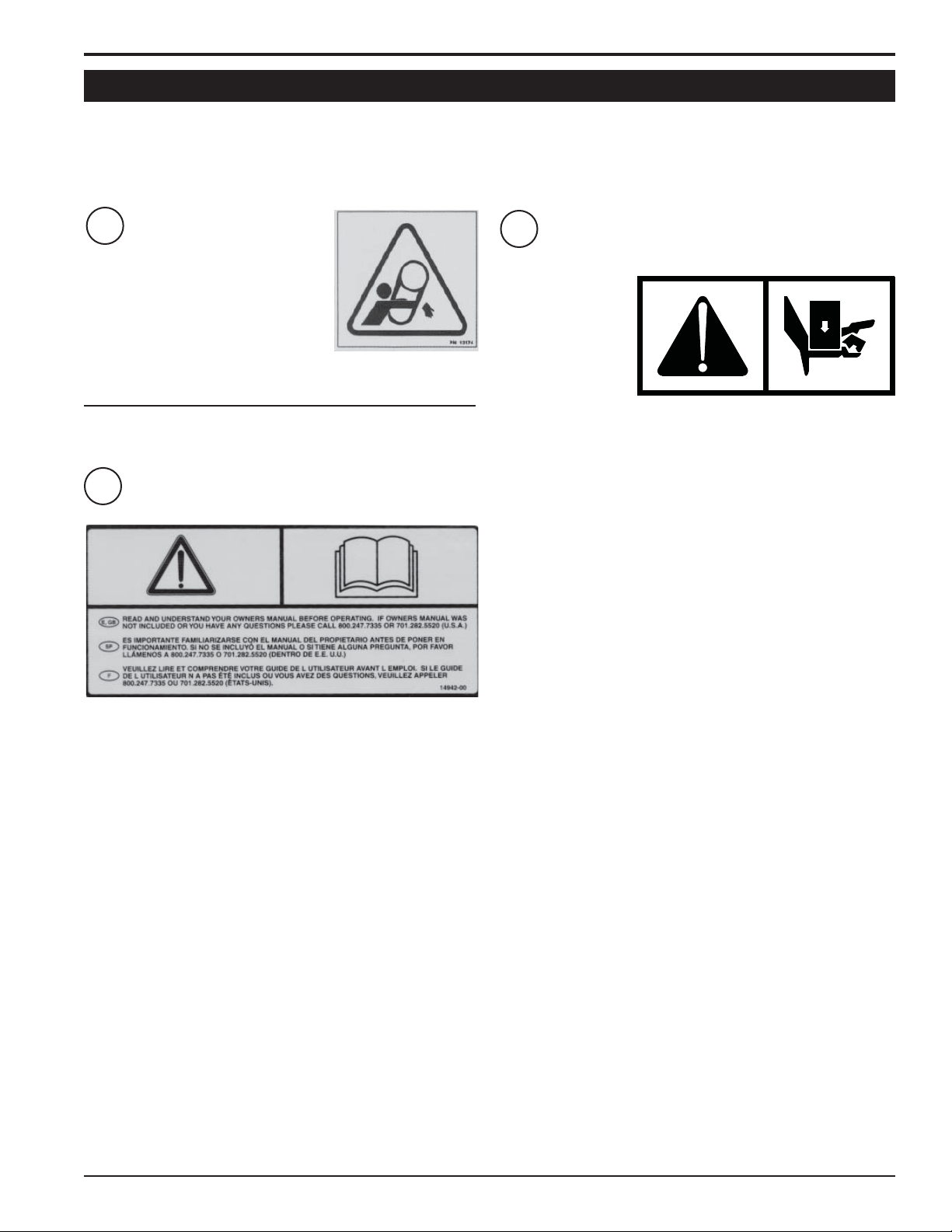
1.7 SAFETY DECALS
See Section 1.6 for decal locations. Familiarize yourself with all of the safety and operating decals on the machine
and the associated hazards. See the engine owner’s manual or contact the engine manufacturer for engine safety
instructions and decals. Make certain that all safety and operational decals on this machine are kept clean and in good
condition. Decals that need replacement must be applied to their original locations.
1
DO NOT OPERATE MACHINE
WITHOUT SHIELDS IN PLACE.
FAILURE TO DO SO MAY CAUSE
SERIOUS INJURY OR DEATH.
2
PN 12174
PN 14942-00
3
TURN ENGINE
OFF BEFORE
SERVICING
MACHINE. KEEP
ALL BODY PARTS
CLEAR OF THE
CUTTING AREA
WHILE SPLITTING
WEDGE IS IN MOTION. THE HYDRAULIC CYLINDER AND
SPLITTING WEDGE CAN CAUSE SEVERE BODILY HARM.
BEFORE OPERATING LOG SPLITTER, CONSULT OWNERS
MANUAL FOR PROPER OPERATION AND MAINTENANCE
TECHNIQUE.
PN 18983-00
READ AND UNDERSTAND THIS OWNER/OPERATORS MANUAL. BE COMPLETELY FAMILIAR WITH THE CONTROLS
AND THE PROPER USE OF THIS EQUIPMENT.
5LOG SPLITTER
Page 10

2
Section
ASSEMBLY
2.1 INSTALL THE HYDRAULIC CYLINDER
The log splitter is shipped with the hydraulic cylinder
moved forward on the main beam. To install the hydraulic
cylinder:
Remove the right hand ledge tube by removing two
1.
snap pins (Figure 1).
Remove the six 3/8" x 3/4" bolts that connect the
2.
cylinder cradle to the main beam.
Slide the hydraulic cylinder and valve assembly back
3.
until the ports at the ram end of the cylinder rest in the
notches of the main beam.
Secure the hydraulic cylinder by reinstalling the cylinder
4.
cradle from step 2. Use the six 3/8" x 3/4" bolts.
Reinstall the right hand ledge tube with the two snap
5.
pins.
2.2 ATTACH THE HITCH
Insert the hitch pole into the hitch channel on the log
1.
splitter trailer.
Insert the provided 3/8" hitch pin through the rear hitch
2.
channel hole and rear hitch tube hole. Secure the hitch
pin with a hairpin clip.
Insert a 3/8" x 3" bolt through the hitch channel and
3.
hitch tube as shown in Figure 2. Install a 3/8" washer
and nylock nut on the bolt. Torque to 30 ft-lbs.
Fig. 1. Hydraulic cylinder installation
Fig. 2. Hitch installation
6 LOG SPLITTER
Page 11

2.3 FILL THE TANK
WARNING
Gasoline and diesel fuels are highly
fl ammable and their vapors are
explosive. To prevent personal injury or
property damage:
Store fuel only in approved containers,
in well ventilated, unoccupied buildings,
away from sparks or fl ames. A container
with a capacity of 2 gallons or less with a pouring spout
is recommended. Do not fi ll the fuel tank while the
engine is hot or running, since spilled fuel could ignite if
it comes in contact with hot parts or sparks from ignition.
Do not start the engine near spilled fuel. Never use fuel
as a cleaning agent. DO NOT MIX OIL WITH FUEL.
Use only those types of fuels that are recommended in
your engine owner’s manual.
To add fuel:
ASSEMBLY
Stop engine, wait for all parts to stop moving and
1.
disconnect spark plug wire. Remove key from key
switch. Allow the engine and muf fler to cool for at least
three minutes.
Clean area around fuel fill cap and remove cap.
2.
Using a clean funnel, fill fuel tank to 1/2” below bottom
3.
of filler neck to provide space for any fuel expansion.
Install fuel fill cap securely and wipe up any spilled
gasoline.
7LOG SPLITTER
Page 12

3
FEATURES & CONTROLS
Section
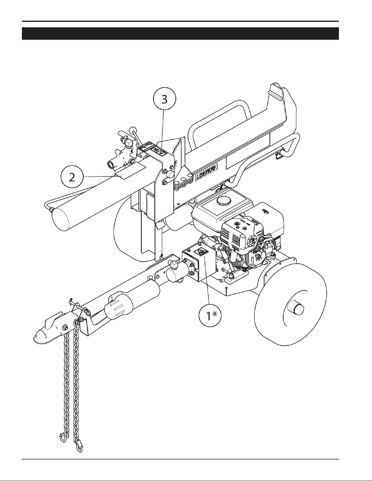
3.1 LOG SPLITTER COMPONENTS
Understanding how your machine works will help you achieve the best results when using your machine. The following
descriptions defi ne the features and controls of your machine.
Hitch safety chains: Safety chains are used during
1.
towing to prevent the machine from completely
separating from the tow vehicle in the event the coupler
detaches from the tow vehicle. Cross the safety chains
under the hitch and connect to the towing vehicle.
Hitch jack: Always have in UP position and clear from
2.
the ground when machine is moving. When machine is
in use, place in DOWN position on a level surface.
Manual holder: Stores owner's manual and safety
3.
goggles for easy access.
Hydraulic pump: The pump provides hydraulic power
4.
to the system.
Hydraulic fluid tank: The hydraulic pump requires
5.
premium hydraulic fluids containing high quality rust,
oxidation, and foam inhibitors. These include premium
turbine oils, API CD engine oils per SAE J183, M2C33F
or G automatic transmission fluids meeting Allison C-3
or Caterpillar TO-2, and certain specialty agricultural
tractor fluids.
Cutting area: Place logs to be cut in the cutting area.
6.
Keep all body parts clear of the cutting area when the
splitting wedge is in motion.
Splitting wedge: The splitting wedge is connected to
7.
the ram of the hydraulic cylinder.
Log splitter control lever: Push the lever toward the
8.
cutting area to extend the ram of the hydraulic cylinder.
Pull the lever away from the cutting area to retract the
ram. The lever will automatically return to the neutral
position when the ram is fully retracted.
Hydraulic cylinder: The ram of the hydraulic cylinder
9.
extends and retracts according to the log splitter control
lever.
Hydraulic filter: Change the hydraulic filter after every
10.
200 hours of operation.
8 LOG SPLITTER
Page 13

3.2 ENGINE COMPONENTS
NOTE
Refer to the engine owner's manual for more detailed
engine information.
Engine choke: Use when starting a cold engine. To
1.
use, push the lever to the left. Gradually turn off as the
engine warms. Full choke may not be necessary when
starting a warm engine. In this case, partial or no choke
may work best.
Fuel cut-off switch: Push lever to the ON position to
2.
start and run engine.
Engine throttle: This changes engine speed. Push
3.
lever all the way to the fast position for full throttle
operation. Push the opposite way for engine idle.
Push all the way to the slow position to shut engine
off. Refer to engine manual for further engine operating
instructions.
Engine switch: Turn to ON position to start and run
4.
engine. To stop, turn to OFF position.
Starter cord: T o start, pull the cord until light resistance
5.
is felt and then pull briskly.
Fuel tank: Fill only with fuel types specified in your
6.
engine owner's manual.
FEATURES & CONTROLS
9LOG SPLITTER
Page 14

4 4
Section
OPERATION
As with any other piece of outdoor equipment, getting the
feel for how your machine operates and getting to know
the best techniques for particular jobs are important to
overall good performance.
WARNING
Move machine to a clear, level area outdoors before
starting. Do not operate in the vicinity of bystanders.
4.1 STARTING THE LOG SPLITTER
Move the machine to a clear, level area outdoors before
starting. Do not operate in the vicinity of bystanders.
Check engine oil and hydraulic oil levels before
1.
starting.
Turn the fuel cut-off switch to the ON position.
2.
Turn the engine switch to the ON position.
3.
Place the throttle control midway between the SLOW
4.
and FAST positions. If starting a cold engine, move the
choke control into the CHOKE position.
Pull the recoil starter until light resistance is felt. Then,
5.
pull briskly. Repeat until the engine starts. Make sure
the starting cord retracts after each pull.
As the engine warms, gradually turn the choke off.
6.
Move the throttle to the FAST position.
7.
4.2 STOPPING THE LOG SPLITTER
Move the throttle to the SLOW position.
1.
Stop the engine by turning the engine switch to the
2.
OFF position.
Turn the fuel cut-off switch to the OFF position.
3.
4.3 OPERATING THE LOG SPLITTER
WARNING
Read and follow all safety instructions in this manual.
Failure to operate the machine in accordance with
the safety instructions MAY RESULT IN PERSONAL
INJURY!
CAUTION
Obtain and wear safety glasses at all times when
operating the machine.
Do not wear loose fitting clothing.
The operator should always wear heavy boots, gloves,
pants and a long-sleeved shirt.
WARNING
Keep all body parts away from the cutting area while the
splitting wedge is in motion.
Ensure the engine is running at full RPM before
1.
attempting to split wood.
Select a log no more than 24 inches (61 cm) in length
2.
to split. The log should be free from foreign materials.
For best results, both ends of the log should be cut
square.
Grasp the log by the sides and place it in the cutting
3.
area. Center the log on the beam. See the images on the
following page for correct and incorrect techniques.
Stand behind the cutting area on the control lever side
4.
of the log splitter.
Using your hand, push the control lever toward the
5.
cutting area. Keep all body parts clear of the cutting
area while the splitting wedge is in motion.
6.
WARNING
Before operating your machine, be sure you read
and understand all safety, controls and operating
instructions in this owner's manual and on your
machine. Failure to follow these instructions can result
in serious injury or property damage.
10 LOG SPLITTER
7.
8.
Hold the control lever in the forward position until either
the log is split or the ram has reached its full extension.
If the log starts to split in an undesired fashion, reverse
the ram, reposition the log and try again.
Pull the control lever back to the reverse position. The
lever will automatically return to the neutral position
when the cylinder is fully retracted. Keep all body parts
clear of the ram while it retracts.
Remove the split pieces and repeat the steps above
with a new log.
Page 15
OPERATION
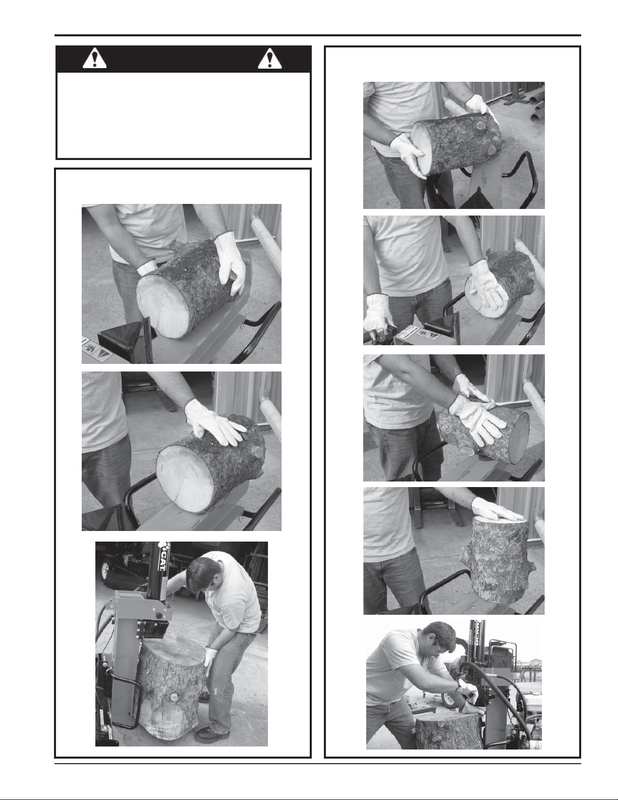
WARNING
If necessary , you may support the log on the main beam
by placing your hand on the side of the log. Do not place
your hand between the log and splitting wedge. Only
support the log with your hand until the splitting wedge
makes contact with the log. Then, remove your hand from
the cutting area, stand clear and resume operation.
CORRECT
INCORRECT
11LOG SPLITTER
Page 16
OPERATION
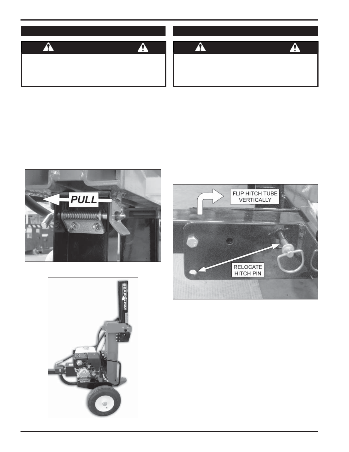
4.4 VERTICAL OPERATION
WARNING
To prevent personal injury or property damage: shut
off engine and make sure that all moving parts have
come to a complete stop before servicing, adjusting or
repairing. Disconnect the spark plug.
The main beam of the log splitter can be flipped vertically
to split wood. Perform the following steps for vertical
operation:
Turn the engine off.
1.
Pull the spring-loaded pin located under the main beam
2.
(see Figure 3).
Lift the base of the hydraulic cylinder to flip the main
3.
beam into vertical position (Figure 4).
Resume normal operation.
4.
4.5 STORAGE MODE
WARNING
To prevent personal injury or property damage: shut
off engine and make sure that all moving parts have
come to a complete stop before servicing, adjusting or
repairing. Disconnect the spark plug.
The log splitter can be adjusted for storing in tight spaces.
Perform the following steps to transform the machine into
storage mode:
Turn the engine off.
1.
Flip the main beam into vertical position (see Section
2.
4.4).
Remove the hitch pin from the hitch channel and hitch
3.
tube. Flip the hitch tube into vertical position (Figure
5).
Secure the hitch tube in the upright position by installing
4.
the hitch pin in the hole below the 3/8" hitch bolt.
Fig. 3. Spring-loaded pin
Fig. 4. Vertical position
Fig. 5. Storage mode
12 LOG SPLITTER
Page 17

5
SERVICE & MAINTENANCE
5.1 MAINTENANCE SCHEDULE
The items listed in this service and maintenance schedule
are to be checked, and if necessary, corrective action
taken. This schedule is designed for units operating under
normal conditions. If the unit is operating in adverse or
severe conditions, it may be necessary for the items to be
checked and serviced more frequently.
SEE ENGINE OWNER’S MANUAL FOR FURTHER
ENGINE MAINTENANCE AND TROUBLESHOOTING
INFORMATION.
SERVICE AND MAINTENANCE SCHEDULE
REFER TO
COMPONENT
AIR CLEANER CHECK AND CLEAN (1)
ENGINE OIL CHECK
ENGINE OIL CHANGE (1)
FUEL FILTER REPLACE
SPARK PLUG
HYDRAULIC OIL CHECK/FILL
FUEL TANK CHECK/FILL
ALL INTERNAL AND
EXTERNAL NUTS AND
BOLTS
MAINTENANCE
REQUIRED
CHECK CONDITION
AND GAP
CHECK TIGHTNESS
OPERATOR’S
MANUAL
WARNING
To prevent personal injury or property damage: shut
off engine and make sure that all moving parts have
come to a complete stop before, servicing, adjusting
or repairing. Disconnect the spark plug.
FREQUENCY
ENGINE
X
X
X
X
BEFORE
EACH
USE
EVERY
HOURS
X
X
X
8
X
EVERY
20
HOURS
EVERY
50
HOURS
EVERY
200
HOURS
ENTIRE MACHINE CLEAN
HYDRAULIC OIL FILTER REPLACE
WHEEL BEARINGS CHECK AND REPACK
TIRE PRESSURE CHECK
(1) PERFORM MORE FREQUENTLY UNDER EXTREMELY DUSTY CONDITIONS.
As the Limited Warranty states, failure by the Owner to perform normal maintenance will void the machine’s warranty.
X
X
X
X
13LOG SPLITTER
Page 18
SERVICE & MAINTENANCE
BEFORE INSPECTING OR SERVICING ANY PART OF THIS MACHINE, SHUT OFF POWER SOURCE,
AND MAKE SURE ALL MOVING PARTS HAVE COME TO A COMPLETE STOP.
WARNING
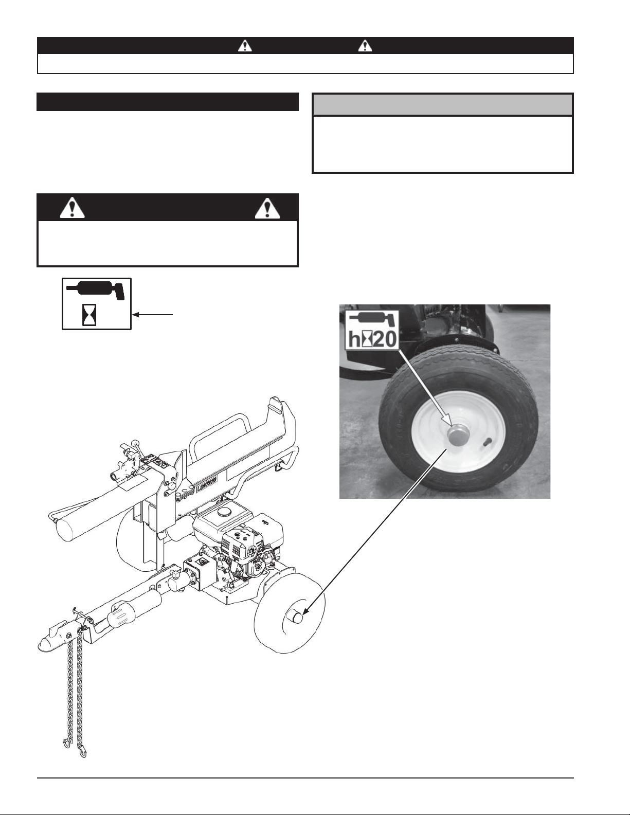
5.2 LUBRICATION
Lubricate the machine periodically with a lithium-based
grease. Extreme working conditions will require more
frequent greasing.
Repack the wheel bearings with grease after every 20-25
hours of use (see Figure 6):
IMPORTANT
Polyurea and lithium-based greases are not compatible.
Mixing the two grease types may lead to premature
failure.
h
50
Greasing frequency
NOTE
Do not over grease bearings. Overfi lling can lead to
excessive heat and/or unseating of the seals. Add
grease slowly and under light pressure. Whenever
possible, rotate bearing slowly while lubricating.
Fig. 6. Wheel bearings
14 LOG SPLITTER
Page 19

WARNING
BEFORE INSPECTING OR SERVICING ANY PART OF THIS MACHINE, SHUT OFF POWER SOURCE,
AND MAKE SURE ALL MOVING PARTS HAVE COME TO A COMPLETE STOP.
5.3 FILLING HYDRAULIC FLUID
Check the fl uid level with the dipstick before each use.
The hydraulic pump requires premium hydraulic fl uids
containing high quality rust, oxidation, and foam inhibitors.
These include premium turbine oils, API CD engine oils
per SAE J183, M2C33F or G automatic transmission
fl uids meeting Allison C-3 or Caterpillar TO-2, and certain
specialty agricultural tractor fl uids.
The hydraulic tank dipstick is located by the engine. See
Figure 7 for reference. Check the fl uid on level ground with
the jack stand in the down position. Do not overfi ll.
SERVICE & MAINTENANCE
Fig. 8. Hydraulic oil fi lter
Fig. 7. Hydraulic fl uid dipstick
5.4 CHANGING HYDRAULIC OIL FILTER
Change the hydraulic oil fi lter (Figure 8) after the fi rst 50
hours of operation and every 200 hours thereafter. To
change the hydraulic oil fi lter:
Using an oil filter wrench, turn the filter
1.
counterclockwise.
Once the filter becomes loose, turn it out the rest of the
2.
way with your hand.
Properly discard old filter.
3.
Lube the rubber seal on the new filter (PN 16588) with
4.
clean hydraulic oil.
Install the filter onto the threaded pipe. Turn with your
5.
hand until the filter is finger tight.
Using an oil filter wrench, tighten the filter another ½
6.
turn.
Check hydraulic oil level and fill if necessary.
7.
5.5 TRAILER SERVICE TIPS
Check wheel bolt torque monthly.
1.
Check air pressure in tires monthly.
2.
Check and repack wheel bearings with grease after
3.
every 20-25 hours of use.
When towing, always connect the safety chains. Make
4.
sure trailer hitch bolts are tight.
Check trailer lights periodically.
5.
Towing speed must not exceed 45 mph (72 kph).
6.
15LOG SPLITTER
Page 20

6
TROUBLESHOOTING
Section
Before performing any of the corrections in this troubleshooting chart, refer to the appropriate information contained in
this manual for the correct safety precautions and operating or maintenance procedures. Contact your dealer or the
factory for service problems with the machine.
PROBLEM POSSIBLE CAUSES REMEDY
Improper control settings. Use proper settings.
Lack of fuel. Fill fuel tank.
Engine will not start.
Engine overheats.
Engine stalls while
splitting wood
Trailer sways during
towing.
Log splitter loses
hydraulic power.
Hydraulic cylinder will not
extend with control lever
in forward position.
Hydraulic cylinder will not
retract with control lever
in reverse position.
Spark plug disconnected. Connect spark plug.
Dirty, stale or contaminated gas. Refill gas tank with fresh, clean unleaded regular gasoline.
Internal engine problems. See your engine dealer.
Cooling system plugged. Clean cooling fan and fins.
Improper oil level. Fill engine to correct oil level. Refer to the engine owners manual.
Engine not operating at full RPM. Move engine throttle to maximum RPM.
Tire air pressure not correct Check tire sidewall for inflation limits.
Low hydraulic fluid levels. Check the hydraulic fluid tank and fill if needed.
There is a leak in the hydraulic
system.
Hydraulic fluid level is low. Check hydraulic fluid level.
Damaged coupler.
Damaged hydraulic cylinder. Replace the cylinder if needed.
Damaged hydraulic motor. Replace the motor if needed.
The splitting wedge or track is
damaged.
The valve assembly is not
functioning properly.
Check for hydraulic fluid leaks by using a piece of cardboard. Do
not check for leaks with your hands or other body parts.
Check the coupler that connects the engine shaft to the hydraulic
pump. Replace if needed.
Check for damage. Replace parts if needed.
Check valve assembly. Replace if needed.
16 LOG SPLITTER
Page 21

7
SPECIFICATIONS
Section
7.1 MACHINE SPECIFICATIONS
DESCRIPTION English Metric
OVERALL SIZE 45.75" x 75.7" x 38.4" 116.2cm x 192.3cm x 97.5cm
OVERALL WEIGHT 415 lbs. 188 kg
STARTER Recoil Recoil
DRIVE TYPE Hydraulic Hydraulic
TIRE SIZE 4.8-8 4.8-8
ENGINE 270cc Honda 270cc Honda
FUEL TANK CAPACITY 1.4 gallons 5.3 liters
HYDRAULIC OIL TANK CAPACITY 5 gallons 18.9 liters
HYDRAULIC PUMP TYPE 2 stage Haldex, 13 gpm 2 stage Haldex, 49.2 lpm
HYDRAULIC CYLINDER FORCE 27 tons 24.5 metric tons
HYDRAULIC CYLINDER STROKE 24 in. 61 cm
HITCH TYPE 2 in. coupler 50mm coupler
LS27270
LS27270T
DESCRIPTION English Metric
OVERALL SIZE 45.75" x 75.7" x 38.4" 116.2cm x 192.3cm x 97.5cm
OVERALL WEIGHT 430 lbs. 195 kg
STARTER Recoil Recoil
DRIVE TYPE Hydraulic Hydraulic
TIRE SIZE 4.8-8 4.8-8
ENGINE 270cc Honda 270cc Honda
FUEL TANK CAPACITY 1.4 gallons 5.3 liters
HYDRAULIC OIL TANK CAPACITY 5 gallons 18.9 liters
HYDRAULIC PUMP TYPE 2 stage Haldex, 13 gpm 2 stage Haldex, 49.2 lpm
HYDRAULIC CYLINDER FORCE 27 tons 24.5 metric tons
HYDRAULIC CYLINDER STROKE 24 in. 61 cm
HITCH TYPE 2 in. coupler 50mm coupler
17LOG SPLITTER
Page 22

SPECIFICATIONS
7.2 BOLT TORQUE
The tables below are for reference purposes only and their use by anyone is entirely voluntary , unless otherwise noted.
Reliance on their content for any purpose is at the sole risk of that person and any loss or damage resulting from the
use of this information is the responsibility of that person.
SAE
SAE - 2
SAE - 5
SAE - 8
BOLT DIAMETER
Grade
and
Head
A
Markings
ENGLISH
BOLT DIAMETER (A)
1/4” 7.5 5.5 11 8 16 12
5/16” 15 11 23 17 34 25
3/8” 27 20 41 30 61 45
7/16” 41 30 68 50 95 70
1/2” 68 50 102 75 149 110
9/16” 97 70 149 110 203 150
5/8” 122 90 203 150 312 230
3/4” 217 160 353 260 515 380
7/8” 230 170 542 400 814 600
1” 298 220 786 580 1220 900
1-1/8” 407 300 1085 800 1736 1280
1-1/4” 570 420 2631 1940 2468 1820
METRIC
Grade
and
Head
Markings
4.8
4.8
SAE 2 SAE 5 SAE 8
N.m Ft-lb. N.m Ft-lb. N.m Ft-lb.
8.8
8.8 10.9
10.9
BOLT TORQUE *
12.9
12.9
BOLT DIAMETER
A
METRIC
BOLT DIAMETER
(A)
M3 0.5 0.4 - - - - - M4 3 2.2 - - - - - M5 5 4 - - - - - M6 6 4.5 11 8.5 17 12 19 14.5
M8 15 11 28 20 40 30 47 35
M10 29 21 55 40 80 60 95 70
M12 50 37 95 70 140 105 165 120
M14 80 60 150 110 225 165 260 190
M16 125 92 240 175 350 255 400 300
M18 175 125 330 250 475 350 560 410
M20 240 180 475 350 675 500 800 580
M22 330 250 650 475 925 675 1075 800
M24 425 310 825 600 1150 850 1350 1000
M27 625 450 1200 875 1700 1250 2000 1500
4.8 8.8 10.9 12.9
N.m Ft-lb. N.m Ft-lb. N.m Ft-lb. N.m Ft-lb.
* Torque value for bolts and capscrews are identified by their head markings.
Torque figures indicated above are valid for non-greased or non-oiled threads and heads unless otherwise specified. Therefore, do not
grease or oil bolts or capscrews unless otherwise specified in this manual. When using locking elements, increase torque values by 5%.
BOLT TORQUE *
18 LOG SPLITTER
Page 23

Page 24

ECHO BEARCAT
237 NW 12th Street, West Fargo, ND 58078-0849
Phone: 701.282.5520 • Toll Free: 800.247.7335
Fax: 701.282.9522 •
E-mail: service@crary.com • opesales@crary.com
www.BearCatProducts.com
 Loading...