


3 INCH |
|
|
propiÉtairedu |
||
CHIPPER/SHREDDERS |
|||||
|
|||||
70050 |
- 5.5 HP |
75311 - 11 HP |
- manuel |
||
70080 |
- 8 HP |
70050S |
- 5 HP |
||
|
|
|
|
f |
|
70085 |
- 8 HP ELECTRIC |
70080S |
- 8 HP ELECTRIC |
|
|
70180 |
- 8 HP |
70180S |
- 8 HP |
delmanualpropietario |
|
70380 |
- 8 HP |
70380S |
manualOwner's |
||
- 8 HP |
|
||||
70385 |
- 8 HP ELECTRIC |
70580S |
- 8 HP ELECTRIC |
|
|
70580 |
- 8 HP TOWABLE |
|
|
|
|
|
|
|
en - |
es - |
|
MADE WITH PRIDE IN THE...
PN: 14846-00 R071204
Companion to 14849-00
owner's manual

Before You Begin
DEAR ECHO BEAR CAT CUSTOMER
Thank you for purchasing an ECHO Bear Cat product. The ECHO Bear Cat line is designed, tested, and manufactured to give years of dependable performance. To keep your machine operating at peak efficiency, it is necessary to adjust it correctly and make regular inspections. The following pages will assist you in the operation and maintenance of your machine. Please read and understand this manual before operating your machine.
If you have any questions or comments about this manual, please call us toll-free at 1-800-247-7335.
If you have any questions or problems with your machine, please call or write your local authorized ECHO Bear Cat Dealer.
This document is based on information available at the time of its publication. ECHO Bear Cat is continually making improvements and developing new equipment. In doing so, we reserve the right to make changes or add improvements to our product without obligation for equipment previously sold.
PLEASE SEND US YOUR WARRANTY CARD
A warranty card is included in your owner's kit packaged with your machine. Please take the time to fill in the information requested on the card. When you send your completed card to us, we will register your machine and start your coverage under our limited warranty.
PARTS ORDERING INFORMATION
For service assistance or parts, contact your nearest authorized ECHO Bear Cat dealer or the factory. Your nearest authorized dealer will need to know the serial number of your machine to provide the most efficient service. See below for information on how to identify and record the serial number for your machine.
If you need engine service or parts:
For engine service pr parts, contact your nearest authorized engine dealer. An authorized engine dealer can handle all parts, repairs, and warranty service concerning the engine.
REPLACEMENT PARTS
Only genuine ECHO Bear Cat replacement parts should be used to repair the machine. Replacement parts manufactured by others could present safety hazards, even though they may fit on this machine. Replacement parts are available from your
ECHO Bear Cat dealer.
Provide the following when ordering parts:
The SERIAL NUMBER of your machine. The PART NUMBER of the part.
The PART DESCRIPTION. The QUANTITY needed.
SERIAL NUMBER LOCATION
Please record the serial number in the space provided and on the warranty and registration card.
MANUFACTURED BY CRARY INDUSTRIES |
|
|
|
|
||
WEST FARGO, NORTH DAKOTA 58078 U.S.A. |
|
SERIAL NUMBER |
||||
SERIAL NUMBER XXXXXX |
|
|
||||
|
|
|
|
|
||
MANUFACTURED IN U.S.A. |
|
|
|
|
|
|
|
|
|
|
|
|
|
|
|
How to contact ECHO bear cat |
|
|
||
|
|
|
|
|
|
|
address |
|
Phone |
|
hours |
||
|
|
|
|
|
|
|
237 NW 12th Street |
|
800-247-7335 |
opesales@crary.com |
Monday - Friday, |
||
P.O. Box 849 |
|
701-282-5520 |
8 am to 5 pm |
|||
|
service@crary.com |
|||||
West Fargo, ND 58078 |
|
Fax: 701-282-9522 |
Central Time |
|||
|
|
|
||||
|
|
|
|
|
|
|
© 2006, Crary industries, all rights reserved. produced and printed in the u.s.a.

LIMITED WARRANTY
This warranty applies to all AG and Outdoor Power Equipment manufactured by Crary Industries.
Crary Industries warrants to the original owner each new Crary Industries product to be free from defects in material and workmanship, under normal use and service. The warranty shall extend 1 year from date of delivery for income producing (commercial) applications and 2 years from date of delivery for non-income producing (consumer) use of the product. The product is warranted to the original owner as evidenced by a completed warranty registration on file at Crary Industries. Replacement parts are warranted for (90) days from date of installation.
The warranty registration must be completed and returned to Crary Industries within 10 days of delivery of the product to the original owner or the warranty will be void.
In the event of a failure, return the product, at your cost, along with proof of purchase to the selling Crary Industries dealer. Crary Industries will, at its option, repair or replace any parts found to be defective in material or workmanship. Warranty on any repairs will not extend beyond the product warranty. Repair or attempted repair by anyone other than a Crary Industries dealer as well as subsequent failure or damage that may occur as a result of that work will not be paid under this warranty. Crary Industries does not warrant replacement components not manufactured or sold by Crary Industries.
1.This warranty applies only to parts or components that are defective in material or workmanship.
2.This warranty does not cover normal wear items including but not limited to bearings, belts, pulleys, filters and chipper knives.
3.This warranty does not cover normal maintenance, service or adjustments.
4.This warranty does not cover depreciation or damage due to misuse, negligence, accident or improper maintenance.
5.This warranty does not cover damage due to improper setup, installation or adjustment.
6.This warranty does not cover damage due to unauthorized modifications of the product.
7.Engines are warranted by the respective engine manufacturer and are not covered by this warranty.
Crary Industries is not liable for any property damage, personal injury or death resulting from the unauthorized modification or alteration of a Crary product or from the owner’s failure to assemble, install, maintain or operate the product in accordance with the provisions of the Owner’s manual.
Crary Industries is not liable for indirect, incidental or consequential damages or injuries including but not limited to loss of crops, loss of profits, rental of substitute equipment or other commercial loss.
This warranty gives you specific legal rights. You may have other rights that may vary from area to area.
Crary Industries makes no warranties, representations or promises, expressed or implied as to the performance of its products other than those set forth in this warranty. Neither the dealer nor any other person has any authority to make any representations, warranties or promises on behalf of Crary Industries or to modify the terms or limitations of this warranty in any way. Crary Industries, at its discretion, may periodically offer limited, written enhancements to this warranty.
Crary Industries reserves the right to change the design and/or specifications of its products at any time without obligation to previous purchasers of its products.

|
|
CONTENTS |
|
SECTION |
DESCRIPTION |
PAGE |
|
Safety......................................................................................................................................................................... |
|
3 |
|
1.1 |
The Safety Alert Symbol....................................................................................................................................................................... |
3 |
|
1.2 Emission information............................................................................................................................................................................... |
3 |
||
1.3 before operating..................................................................................................................................................................................... |
3 |
||
1.4 operation safety...................................................................................................................................................................................... |
4 |
||
1.5 Maintenance and storage ...................................................................................................................................................................... |
|
||
|
safety.......................................................................................................................................................................................................... |
|
5 |
1.6 Towing safety............................................................................................................................................................................................ |
|
5 |
|
1.7 battery safety........................................................................................................................................................................................... |
|
5 |
|
1.8 safety decals............................................................................................................................................................................................. |
|
6 |
|
1.9 safety decal locations.......................................................................................................................................................................... |
8 |
||
|
1.9.1 MODEL 70050...................................................................................................................................................................................... |
8 |
|
|
1.9.2 MODELS 70080, 70085, 70180, 70380, 70385.................................................................................................................................... |
8 |
|
|
1.9.3 MODEL 70580...................................................................................................................................................................................... |
8 |
|
|
1.9.4 MODEL 70050S.................................................................................................................................................................................... |
9 |
|
|
1.9.5 MODELs 70080S, 70180S, 70380S.................................................................................................................................................... |
9 |
|
|
1.9.6 MODEL70580S..................................................................................................................................................................................... |
9 |
|
Assembly.................................................................................................................................................................. |
|
10 |
|
2.1 INSTALLING THE HANDLE............................................................................................................................................................................ |
10 |
||
2.2 INSTALLING THE hopper........................................................................................................................................................................... |
10 |
||
2.3 INSTALLING THE chipper chute extension....................................................................................................................................... |
10 |
||
2.4 INSTALLING THE wide and narrow discharge assembly............................................................................................................. |
10 |
||
2.5 INSTALLING THE wheels, jack and hitch........................................................................................................................................... |
10 |
||
2.6 installing the battery.......................................................................................................................................................................... |
10 |
||
2.7 checking/adding motor oil to engine............................................................................................................................................. |
11 |
||
2.8 |
filling the tank........................................................................................................................................................................................ |
|
11 |
Features & Controls......................................................................................................................................... |
12 |
||
3.1 engagement handle............................................................................................................................................................................... |
12 |
||
3.2 engine throttle. |
..................................................................................................................................................................................... |
12 |
|
3.3 engine choke............................................................................................................................................................................................ |
|
12 |
|
3.4 key switch.................................................................................................................................................................................................. |
|
13 |
|
3.5 shredder chute...................................................................................................................................................................................... |
|
13 |
|
3.6 shredder knives...................................................................................................................................................................................... |
|
13 |
|
3.7 chipper chute........................................................................................................................................................................................... |
|
13 |
|
3.8 chipper blades......................................................................................................................................................................................... |
|
13 |
|
3.9 jack stand.................................................................................................................................................................................................. |
|
13 |
|
Operation................................................................................................................................................................ |
|
14 |
|
4.1 |
Starting electric models.................................................................................................................................................................. |
14 |
|
4.2 |
Starting recoil models....................................................................................................................................................................... |
14 |
|
4.3 |
Stopping the Chipper/Shredder...................................................................................................................................................... |
15 |
|
4.4 |
Chipping Guide......................................................................................................................................................................................... |
|
15 |
4.5 |
shredding Guide..................................................................................................................................................................................... |
15 |
|
Service & Maintenance...................................................................................................................................... |
16 |
||
5.1 |
Maintenance Schedule........................................................................................................................................................................ |
16 |
|
5.2 Chipper Blades......................................................................................................................................................................................... |
|
17 |
|
|
5.2.1 Removing The Blades................................................................................................................................................................. |
17 |
|
|
5.2.2 Sharpening the Blades............................................................................................................................................................. |
17 |
|
|
5.2.3 installing the blades................................................................................................................................................................ |
17 |
|
5.3 Setting Chipping Blade Clearance.................................................................................................................................................. |
18 |
||
5.4 |
Replacing the shredder knives....................................................................................................................................................... |
18 |
|
5.5 |
changing the discharge screen..................................................................................................................................................... |
19 |
|
5.6 |
Belt guide adjustments....................................................................................................................................................................... |
19 |
|
5.7 |
remove/Replace Drive Belt................................................................................................................................................................ |
20 |
|
5.8 |
Clearing a plugged rotor................................................................................................................................................................. |
20 |
|
5.9 |
Removing Rotor |
...................................................................................................................................................................................... |
20 |
5.10 Trailer Service Tips ...................................................................................................................................... |
20 |
||
5.11 greaseable Bearings and Pivots................................................................................................................................................... |
21 |
||
Troubleshooting................................................................................................................................................. |
|
22 |
|
Specifications....................................................................................................................................................... |
|
23 |
|
7.1 |
non-towable models............................................................................................................................................................................ |
23 |
|
7.2 |
towable models |
...................................................................................................................................................................................... |
23 |
7.3 |
bOLT torque.............................................................................................................................................................................................. |
|
24 |
7.4 |
Special Torque Requirements.......................................................................................................................................................... |
25 |
|
3 INCH CHIPPER/SHREDDERS

 1
1 Safety
Section
1.1 The Safety Alert Symbol
The Owner/Operators manual uses this symbol to alert you of potential hazards. Whenever you see this symbol, read and obey the safety message that follows it. Failure to obey the safety message could result in personal injury, death or property damage.
ordinances, or codes. Contact your local fire marshal or forest service for specific information about which regulations apply in your area.
The standard muffler installed on the engine is not equipped with a spark arrester. One must be added before using this machine in an area where a spark arrester is required by law.
Contact the local authorities if these laws apply to you. See your authorized engine dealer for spark arrester options.
DANGER
Indicates an imminently hazardous situation that, if not avoided, will result in death or serious injury.
WARNING
Indicates a potentially hazardous situation that, if not avoided, could result in death or serious injury.
caution
Indicates a potentially hazardous situation that, if not avoided, may result in minor or moderate injury.
1.2 Emission information
WARNING TO ALL CALIFORNIA AND OTHER STATES OPERATING OUTDOOR POWER EQUIPMENT
Under California Law and under the laws of several other states, you are not permitted to operate an internal combustion engine using hydrocarbon fuels on any forest covered, brush covered or grass covered land or on land covered with grain, hay
or other flammable agricultural crops, without an engine spark arrester in continuous effective working order.
The engine on your power equipment, like most outdoor power equipment, is an internal combustion engine that burns gasoline (a hydrocarbon fuel). Therefore, your power equipment must be equipped with a spark arrester muffler in continuous effective working order. The spark arrester must be attached to the engine exhaust system in such a manner that flames or heat from the system will not ignite flammable material.
Failure of the owner/operator of the equipment to comply with this regulation is a misdemeanor under California law and may also be a violation of other state and/or federal regulations, laws,
1.3 before operating
1.Read and understand this Owner/Operators manual. Be completely familiar with the controls and the proper use of this equipment.
2.Familiarize yourself with all of the safety and operating decals on this equipment and on any of its attachments or accessories.
3.Keep safety decals clean and legible. Replace missing or illegible safety decals.
4.Obtain and wear safety glasses and
use hearing protection at all times when operating this machine.
5. Avoid wearing loose fitted clothing. Never operate this machine wearing clothing with drawstrings that could wrap around or get caught in the machine.
6.Do not operate this machine if you are under the influence of alcohol, medications, or substances that can affect your vision, balance or judgement. Do not operate if tired or ill. You must be in good health to operate this machine safely.
7.Do not operate this equipment in
the vicinity of bystanders. Keep the area of operation clear of all persons, particularly small children. It is recommended that bystanders keep at least 50 feet (15 meters) away from the area of operation.
8.Do not allow children to operate this equipment.
9.Use only in daylight or good artificial light.
3 INCH CHIPPER/SHREDDERS
SAFETY
10.Do not run this equipment in an enclosed area. Engine exhaust contains carbon monoxide gas, a deadly poison that is odorless, colorless and tasteless. Do not operate this equipment in or near buildings, windows or air conditioners.
11.Always use an approved fuel container. Do not remove gas cap or add fuel when engine is running. Add fuel to a cool engine only.
12.Do not fill fuel tank indoors. Keep open flames, sparks, smoking materials and other sources of combustion away from fuel.
13.Do not operate machine without shields in place. Failure to do so may cause serious injury or death.
14.Keep all guards, deflectors, and shields in good working condition.
15.Before inspecting or servicing any part
of this machine, shut off power source, disconnect spark plug wire from spark plug and make sure all moving parts have come to a complete stop.
16. Check that all screws, nuts, bolts, and other fasteners are secured, tightened and in proper working condition before starting the machine and once every 8 hours of operation.
17.Do not transport or move machine while the machine is operating or running.
1.4operation safety
1.Always stand clear of discharge area 
when operating this machine. Keep face
and body away from feed and discharge openings.
2. Keep hands and feet out of feed and  discharge openings while machine is
operating to avoid serious personal injury. Stop and allow machine to come to a complete stop before clearing obstructions.
3.Set up your work site so you are not endangering traffic and the public. Take great care to provide adequate warnings.
4.Do not climb on machine when operating. Keep proper balance and footing at all times.
5.Check cutting chamber to verify it is empty before starting the machine.
6.Lower lever slowly to engage machine. Pull lever up to disengage machine. Chipper/shredder rotor will continue to rotate when clutch is disengaged. Shut off power source, disconnect spark plug wire from spark plug and make sure all moving parts have come to a complete stop. Do not operate without discharge screen, inlet flaps and all shields in place.
7.Do not insert branches larger than 3/4 inch into shredder or machine damage may occur.
8.Do not insert branches larger than 3 inches in diameter into chipper or machine damage may occur.
9. |
When feeding shreddable material into |
3 INCH |
|
machine, do not allow metal, rocks, bottles, |
|
|
cans or any other foreign material to be fed |
|
|
into chipper or shredder. |
|
10. |
Ensure debris does not blow into traffic, |
|
|
parked cars, or pedestrians. |
76 mm |
|
|
11.Keep the machine clear of debris and other accumulations.
12.Do not allow processed material to build up in the discharge area. This may prevent proper discharge and can result in kickback of material through the feed opening.
13.Shut off machine immediately if the machine becomes clogged, the cutting mechanism strikes any foreign object, or the machine starts vibrating or making an unusual noise. Shut off power source, disconnect spark plug wire from spark plug and make sure all moving parts have
come to a complete stop. After machine stops:
A.Inspect for damage.
B.Replace or repair any damaged
parts.
C.Check for and tighten any loose parts.
14.On electric start models, disconnect cables from battery before doing any inspection or service.
15.Check blade bolts for proper torque after every 8 hours of operation. Check blades and rotate or resharpen daily or as required to keep blades sharp. Failure to do so may cause poor performance, damage or personal injury and will void the machine warranty.
3 INCH CHIPPER/SHREDDERS
SAFETY
1 . 5 Maintenance and storage safety
1.Before inspecting, servicing, storing, or changing an accessory, shut off power source, disconnect spark plug wire from spark plug and make sure all moving parts have come to a complete stop.
2.Replace any missing or unreadable safety decals. Refer to the parts manual for part numbers when ordering safety decals from an area ECHO Bear Cat dealer.
3.Allow machine to cool before storing in an enclosure.
4.Store the machine out of reach of children and where fuel vapors will not reach an open flame or spark.
5.Never store this machine with fuel in the fuel tank inside a building where fumes may may be ignited by an open flame or spark. Ignition sources can be hot water and space heaters, furnaces, clothes dryers, stoves, electric motors, etc.
6.Drain the fuel and dispose of it in a safe manner for storage periods of three months or more.
1.6 Towing safety
1.Towing laws may vary in different countries/regions/states. It is recommended that you contact your local motor vehicle department for any special rules that pertain to towing and to know the rules of any country/region/state you may travel through.
2.Connect hitch safety chains. Tighten and secure trailer hitch bolts. Do not attempt to tow the trailer if vehicle is not equipped with the proper size hitch ball.
3.Check wheel lug bolts periodically to ensure they are tight and secure.
4.Place the jack stand on the trailer in the UP position to clear the ground while towing. Place the jack stand on a level surface and secure it in the DOWN position before using.
5.Never allow passengers to ride on the chipper.
6.If applicable, shut off fuel supply when towing.
1.7 battery safety
Improper use and care of the battery on electric start models can result in serious personal injury or property damage. Always observe the following safety precautions.
1.Danger / Poison - Causes Severe Burns. The battery contains sulfuric acid. Avoid contact with skin, eyes or clothing. Keep out of reach of children.
ANTIDOTE-External Contact: Flush immediately with lots of water.
ANTIDOTE-Internal: Drink large quantities of water or milk. Follow with milk of magnesia, beaten egg or vegetable oil. Call a physician immediately.
ANTIDOTE-Eye Contact: Flush with water for 15 minutes. Get prompt medical attention.
danger / PoiSon
FLusH EyEs
ImmEdIATELy
WITH WATER
EyEs |
|
NO |
|
suLFuRIC |
|
|
|
|
|
|
|||
ExPLOsIvE gAsEs |
|
|
ACId |
|
gET |
|
|
|
|
||||
CAN CAusE |
|
• sPARks |
|
CAN CAusE |
|
mEdICAL |
|
|
|
||||
|
|
|
||||
BLINdNEss OR |
|
• FLAmEs |
|
BLINdNEss OR |
|
HELP |
|
|
|
||||
INjuRy |
|
• smOkINg |
|
sEvERE BuRNs |
|
FAsT |
|
|
|
||||
|
|
|
kEEP OuT OF THE REACH OF CHILdREN. dO NOT TIP. kEEP vENT CAPs TIgHT ANd LEvEL.
2.The battery produces explosive gases. Keep sparks, flame or cigarettes away. Ventilate area when charging battery. Always wear safety goggles when working near battery.
3.The battery contains toxic materials. Do not damage battery case. If case is broken or damaged, avoid contact with battery contents.
4.Neutralize acid spills with a baking soda and water solution.
5.Properly dispose of a damaged or worn-out battery. Check with local authorities for proper disposal methods.
6.Do not short circuit battery. Severe fumes and fire can result.
7.Before working with electrical wires or components, disconnect the negative (-) cable first. Disconnect the positive
(+)cable second. Reverse this order when reconnecting battery cables.
3 INCH CHIPPER/SHREDDERS
SAFETY
1.8 safety decals
See Section 1.9 for decal locations. Familiarize yourself with all of the safety and operating decals on the machine and the associated hazards. See the engine owners manual or contact the engine manufacturer for engine safety instructions and decals. Make certain that all safety and operational decals on this machine are kept clean and in good condition. The decals are shown below at reduced sizes. Refer to the parts catalog if you need a replacement decal. Decals that need replacement must be applied to their original locations.
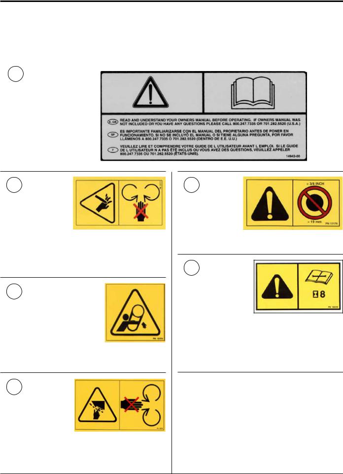
1
P/N 14942-00
2
P/N 12171
KEEP HANDS AND FEET OUT OF INLET AND DISCHARGE OPENINGS WHILE MACHINE IS OPERATING TO AVOID SERIOUS PERSONAL INJURY. STOP AND ALLOW MACHINE TO COME TO A COMPLETE STOP BEFORE CLEARING OBSTRUCTIONS.
3
P/N 12174
DO NOT OPERATE MACHINE WITHOUT SHIELDS IN PLACE. FAILURE TO DO SO MAY CAUSE SERIOUS INJURY OR DEATH.
4
P/N 12175
KEEP HANDS AND FEET OUT OF INLET AND DISCHARGE OPENINGS WHILE MACHINE IS OPERATING TO AVOID SERIOUS PERSONAL INJURY. STOP AND ALLOW MACHINE TO COME TO A COMPLETE STOP BEFORE CLEARING OBSTRUCTIONS.
5
P/N 12176
DO NOT INSERT BRANCHES LARGER THAN 3/4 INCH INTO SHREDDER OR MACHINE DAMAGE MAY OCCUR.
6
P/N 12250
CHECK BLADE BOLTS FOR PROPER TORQUE AFTER EVERY 8 HOURS OF OPERATION. CHECK BLADES AND ROTATE OR RESHARPEN DAILY OR AS REQUIRED TO KEEP BLADES SHARP. REFER TO OWNERS MANUAL FOR INSTRUCTIONS. FAILURE TO DO SO MAY CAUSE POOR PERFORMANCE, DAMAGE OR PERSONAL INJURY AND WILL VOID THE MACHINE WARRANTY.
3 INCH CHIPPER/SHREDDERS
SAFETY
7
P/N 14938-00
DO NOT INSERT BRANCHES LARGER THAN 3 INCHES IN DIAMETER INTO CHIPPER. MACHINE DAMAGE MAY OCCUR. REFER TO OWNERS MANUAL FOR OPERATING INSTRUCTIONS AND RECOMMENDATIONS.
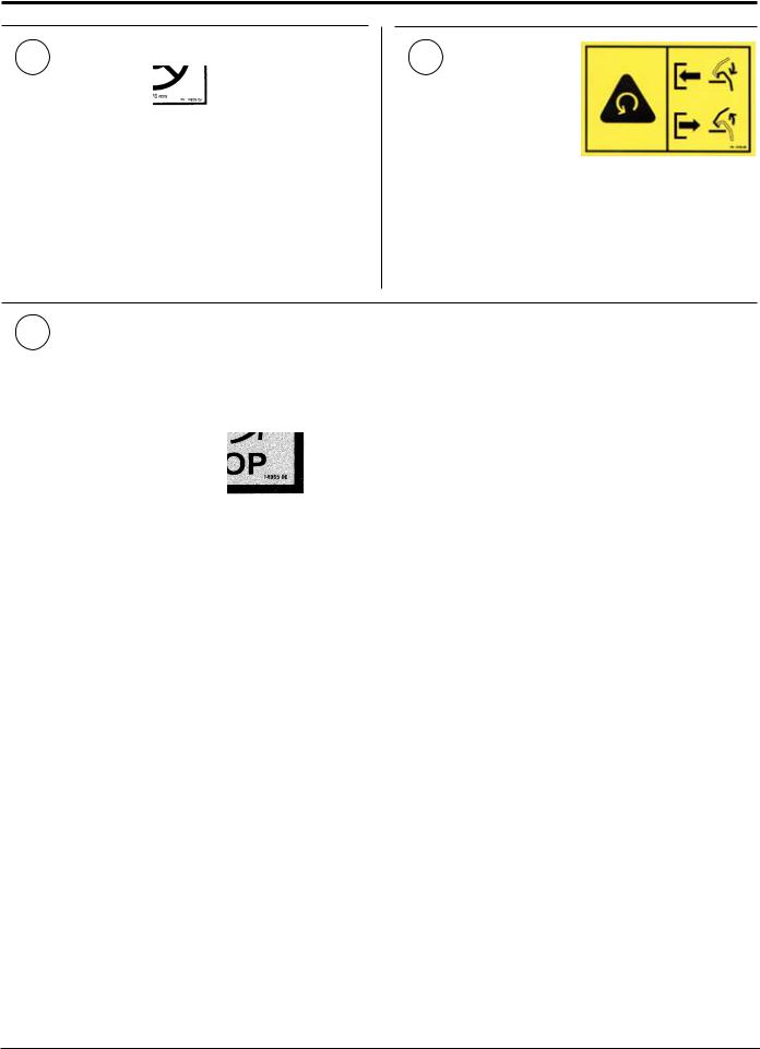
8
P/N 14703-00
LOWER LEVER SLOWLY TO ENGAGE CHIPPER. PULL LEVER UP TO DISENGAGE CHIPPER. CHIPPER/ SHREDDER ROTOR WILL CONTINUE TO ROTATE WHEN CLUTCH IS DISENGAGED. STOP ENGINE AND REMOVE SPARK PLUG WIRE BEFORE CLEANING DEBRIS FROM DISCHARGE AREA OR SERVICING THIS MACHINE. DO NOT OPERATE WITHOUT DISCHARGE SCREEN, INLET FLAPS AND ALL SHIELDS IN PLACE.
9 |
P/N 14965-00 |
|
DO NOT OPERATE THIS
EQUIPMENT IN THE VICINITY OF
BYSTANDERS. DO NOT ALLOW
CHILDREN TO OPERATE THIS
EQUIPMENT.
OBTAIN AND WEAR SAFETY
GLASSES AND USE HEARING
PROTECTIONATALLTIMES WHEN
OPERATING THIS MACHINE.
BEFORE INSPECTING OR
SERVICING ANY PART OF THIS
MACHINE, SHUT OFF POWER
SOURCE, DISCONNECT SPARK
PLUG WIRE FROM SPARK PLUG
AND MAKE SURE ALL MOVING
PARTS HAVE COME TO A
COMPLETE STOP.
ALWAYS STAND CLEAR OF DISCHARGE AREA WHEN OPERATING THIS MACHINE. KEEP FACE AND BODY AWAY FROM FEED AND DISCHARGE OPENINGS.
WHEN FEEDING SHREDDABLE MATERIAL INTO CHIPPER, DO NOT ALLOW METAL, ROCKS, BOTTLES, CANS OR ANY OTHER FOREIGN MATERIAL TO BE FED INTO CHIPPER OR SHREDDER.
BEFORE INSPECTING OR SERVICING ANY PART OF THIS MACHINE, SHUT OFF POWER SOURCE, DISCONNECT SPARK PLUG WIRE FROM SPARK PLUG AND MAKE SURE ALL MOVING PARTS HAVE COME TO A COMPLETE STOP.
3 INCH CHIPPER/SHREDDERS
SAFETY
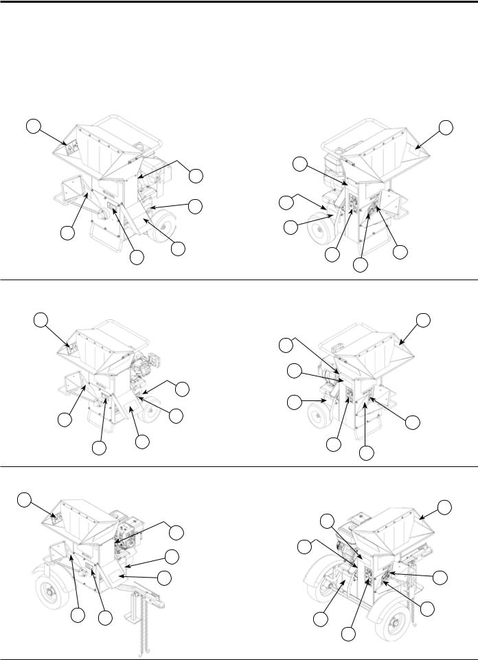
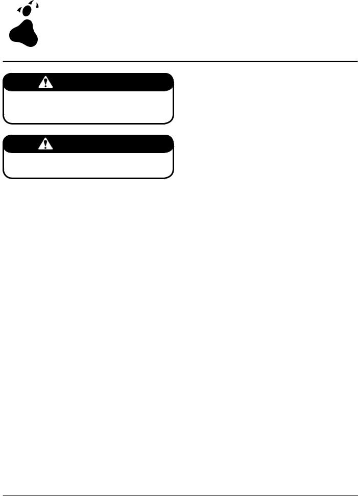
1.9 safety decal locations
The numbers below correspond to the decals in Section 1.8. Familiarize yourself with all of the safety and operational decals on the machine and the associated hazards. See the engine owners manual or contact the engine manufacturer for engine safety instructions and decals. Make certain that all safety and operating decals on this machine are kept clean and in good condition. The decals are shown below at reduced sizes. Refer to the parts catalog if you need a replacement decal. Decals that need replacement must be applied to their original locations.
1.9.1MODEL 70050
4 |
|
|
5 |
|
3 |
1 |
|
|
|
|
|
|
4 |
3 |
|
1 |
|
8 |
|
|
|
|
|
6 |
4 |
9 |
7 |
|
|||
|
|
|
4 |
1.9.2MODELS 70080, 70085, 70180, 70380, 70385
4 |
|
|
5 |
|
|
3 |
|
|
|
1 |
|
|
|
3 |
|
|
4 |
8 |
|
1 |
|
7 |
|
6 |
4 |
9 |
4 |
|
|
|
1.9.3MODEL 70580
4 |
|
5 |
|
|
|
|
3 |
1 |
|
3 |
|
|
4 |
|
|
|
|
4 |
7 |
1 |
6 |
4 |
8 |
||
|
|
9 |
3 INCH CHIPPER/SHREDDERS

SAFETY
1.9.4MODEL 70050S
4 |
|
|
5 |
|
|
|
|
|
|
3 |
1 |
|
|
|
|
4 |
|
4 |
3 |
|
|
||
|
|
8 |
|
7 |
|
|
|
1 |
6 |
4 |
9 |
|
|
1.9.5MODELs 70080S, 70180S, 70380S
5
4 |
|
|
|
|
|
3 |
1 |
|
|
|
|
|
|
4 |
3 |
4 |
|
|
|
|
|
|
|
7 |
|
|
8 |
|
|
|
|
1 |
|
|
|
6 |
4 |
|
9 |
1.9.6MODEL70580S
4 |
|
|
|
5 |
|
|
|
|
|
|
|
|
3 |
1 |
4 |
|
|
|
|
|
|
3 |
|
|
|
|
|
|
|
7 |
|
|
4 |
|
|
|
|
8 |
|
1 |
6 |
|
|
|
4 |
|
9 |
||
|
|
|
3 INCH CHIPPER/SHREDDERS
 2
2 Assembly
Section
warning
Before inspecting or servicing any part of this machine, shut off power source, disconnect spark plug wire from spark plug and make sure all moving parts have come to a complete stop.
important
If any bolts or nuts are dropped in the machine, be sure to remove them before starting the machine. Remove items from the shredder area by removing the discharge screen.
2.4INSTALLING THE wide and narrow discharge assembly
Models: All “S” models
1.Place the discharge weldment onto the chipper. The holes on the weldment should line up with holes on the chipper.
2.Secure the top of the discharge weldment using one 5/16" x 7-1/2" bolt (narrow door) or one 5/16" x 10" bolt (wide door) and 5/16" nuts. Tighten to proper torgue
3.Secure the bottom of the discharge weldment using two 5/16" x 3/4" bolts and 5/16" nuts. The head of the bolt should be located inside the discharge assembly. Tighten to the proper torque.
2.1 INSTALLING THE HANDLE
Models: All models except 70580 & 70580S
1.Remove the chipper/shredder and hopper assembly from the shipping box and pallet.
2.Install four 5/16" X 3/4" bolts so the head of the bolt is located on the inside of the hopper. Fasten bolts with 5/16" nylock nuts and 5/16" flat washers.
2.2 INSTALLING THE hopper
Models: All models
1.Assemble the hopper assembly to the frame so the handle is located above the engine and the opening is toward the chipper chute.
2.Install twelve 5/16" X 3/4" bolts so the head of the bolt is inside the hopper. Fasten bolts with 5/16" flat washers and 5/16" nylock nuts.
2.3INSTALLING THE chipper chute extension
Models: All “S” models
1.Place the chipper chute extension onto the chute. Line up the four holes located on the bottom of the extension and the top of the chute.
2.Install four 5/16" X 3/4" bolts so the head of the bolt is located on the inside of the chipper chute. Fasten bolts with 5/16" nuts. Tighten nut until snug against the chute extension.
2.5INSTALLING THE wheels, jack and hitch
Models: 70580 & 70580s
1.Slide one wheel onto a hub and align the wheel lug holes with the hub lug holes.
2.Thread the wheel bolts into the holes and tighten to the proper torque. Follow an alternating cross pattern when tightening wheel bolts.
3.Repeat for the remaining wheel.
4.Install hitch jack onto hitch pole and install snap pin.
5.Align the hitch pole assembly to the frame and secure using two 3/8" X 2-1/2" bolts, 3/8" flat washers and 3/8" nylock nuts.
2.6 installing the battery
Models: 70085 & 70385
The machine may or may not have been shipped with a battery depending on your area. If you did not receive a battery with your machine, you will need to purchase one.
Use a battery that meets or exceeds the following specifications:
Battery Category, Lawn and Garden BCI Group Size U1
200-250 CCA
7-3/4" X 5-3/16" X 7-5/16" Suggested Source:
Exide Cutting Edge, Type GT-H
After purchasing your battery, fill, charge and install the battery according to the battery owners manual.
10 |
3 INCH CHIPPER/SHREDDERS |
ASSEMBLY
warning
To avoid sparks and a possible explosion or fire due to a short circuit:
Do not touch the positive (+) battery terminal and any surrounding metal with tools, jewelry or other metal objects.
When installing battery cables, connect the positive (+) cable first and the negative (-) cable last.
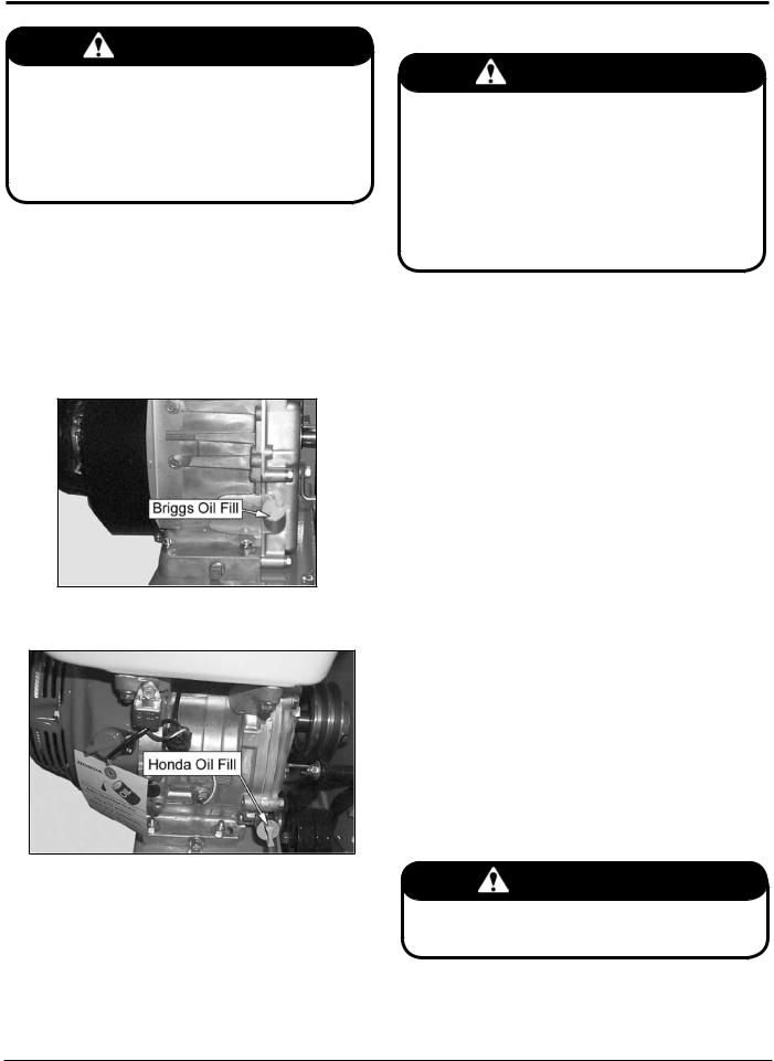
2.7checking/adding motor oil to engine
Models: All models
Check the oil level and if needed fill the engine crankcase with the type and amount of oil specified in the engine owners manual.
Figure 2.1 - Briggs Oil Fill
Figure 2.2 - Honda Oil Fill
2.8 filling the tank
danger
Gasoline is highly flammable and its vapors are explosive.To prevent personal injury or property damage:
Store gasoline only in approved containers, in well ventilated, unoccupied buildings, away from sparks or flames. Do not fill the fuel tank while the engine is
hot or running. Spilled fuel could ignite if it comes in contact with hot parts or sparks from ignition. Do not start the engine near spilled fuel. Never use gasoline as a cleaning agent.
Fuel Type
For best results use only clean, fresh, unleaded gasoline with a pump sticker octane rating of 87 or higher. In countries using the Research method, it should be 90 octane minimum.
Purchase gasoline in small quantities and store in clean, approved containers. A container with a capacity of 2 gallons or less with a pouring spout is recommended. Such a container is easier to handle and helps eliminate spillage during refueling. DO NOT MIX OIL WITH GASOLINE.
Gasoline Alcohol blends
Gasohol (up to 10% ethyl alcohol, 90% unleaded gasoline by volume) is approved as a fuel for Briggs and Honda engines. Other gasoline/alcohol blends are not approved.
Gasoline Ether blends
Methyl Tertiary Butyl Ether (MTBE) and unleaded gasoline blends (up to a maximum of 15% MTBE by volume) are approved as a fuel for Briggs and Honda engines. Other gasoline/ether blends are not approved.
To Add Gasoline
1.Stop engine, wait for all parts to stop moving and disconnect spark plug wire. Remove key from key switch. Allow the engine and muffler to cool for at least three minutes.
2.Clean area around fuel fill cap and remove cap.
3.Using a clean funnel, fill fuel tank to 1/2" below bottom of filler neck to provide space for any fuel expansion. Install fuel fill cap securely and wipe up any spilled gasoline.
important
Do not attempt to start the engine at this time. Wait until you have read the complete starting instructions in the Operation Section of this manual.
3 INCH CHIPPER/SHREDDERS |
11 |
 3
3 Features & Controls
Section
Understanding how your machine works will help you achieve the best results when using your chipper/shredder. The following descriptions define the features and controls of your machine.
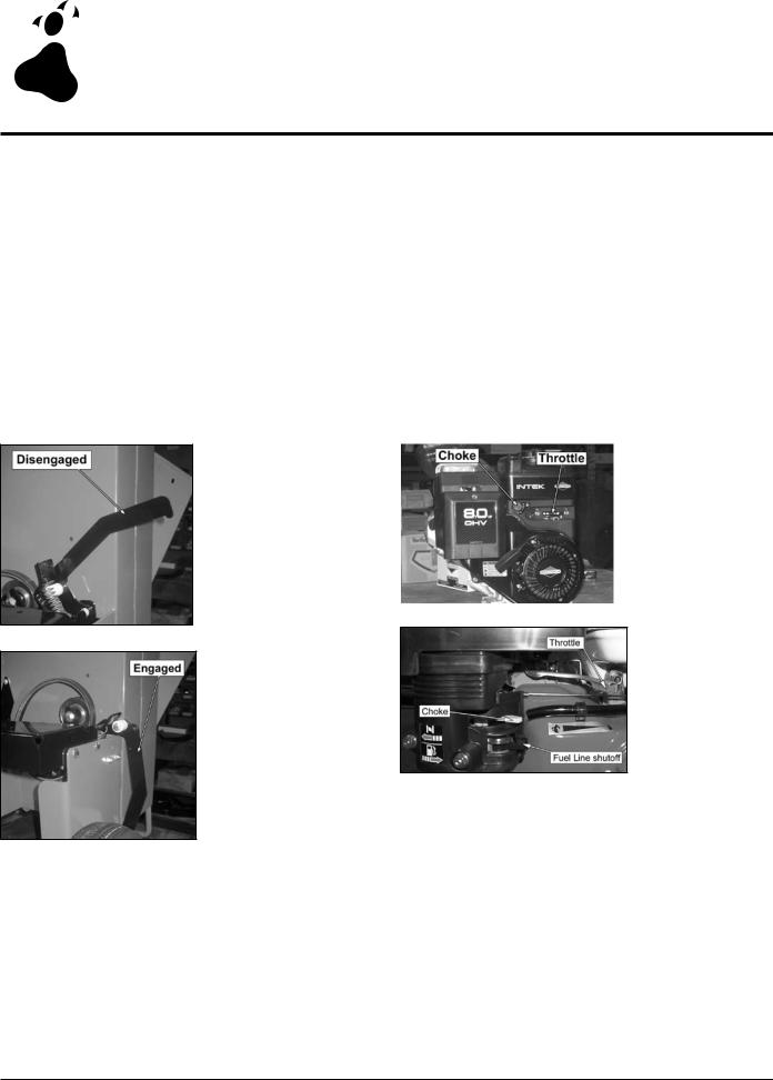
3.1 engagement handle
Models: All models
During engine start-up, the engagement handle must be in the disengaged position (Figure 3.1). With engine at full throttle, carefully engage the rotor by slowly pushing the engagement handle down, allowing the rotor to speed up gradually (Figure 3.2). Engaging the clutch too quickly with the engine at full or half throttle will bog down the engine and will shorten the life of the belt. To disengage the rotor, first idle the engine down and then lift the engagement handle up
3.2 engine throttle
Models: All models
Changes engine speed. Push lever to 1/2 throttle for starting. Push lever to slow for idle and warm-up. Push throttle lever to slow throttle to shut engine off. Refer to engine manual for further engine operating instructions. When chipping or shredding, the engine should be at full throttle.
3.3 engine choke
Models: All models
Use when starting a cold engine. Move lever to the choke position when starting. Move lever to the run position when engine is running (Figures 3.3 and 3.4). Refer to engine manual for further engine operating instructions.
|
|
Figure 3.3 |
Figure 3.1 |
|
Briggs Throttle and |
Disengaged Clutch |
|
Choke Locations |
|
|
|
Figure 3.4
Honda Throttle and
Choke Locations
Figure 3.2
Engaged Clutch
12 |
3 INCH CHIPPER/SHREDDERS |
FEATURES & CONTROLS
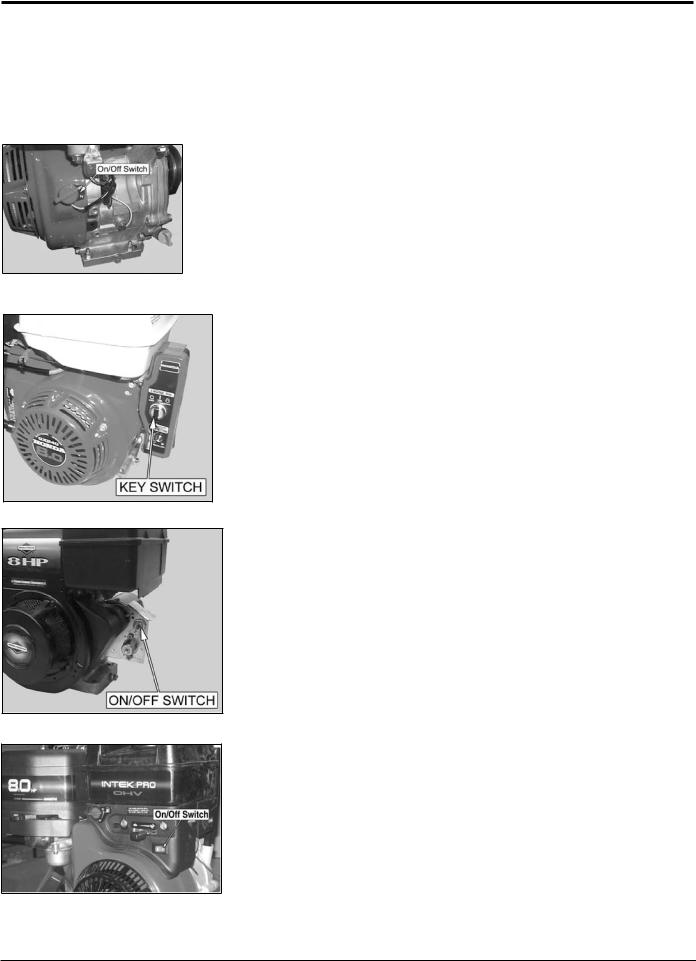
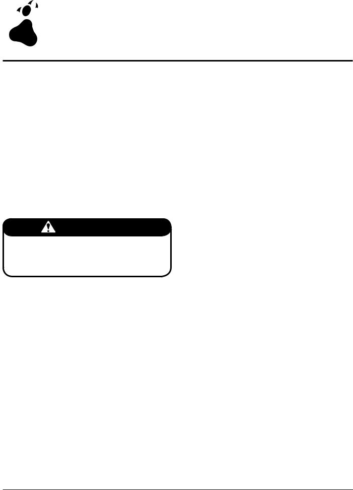
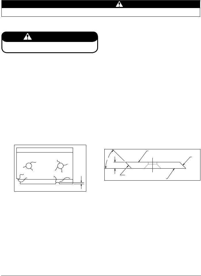
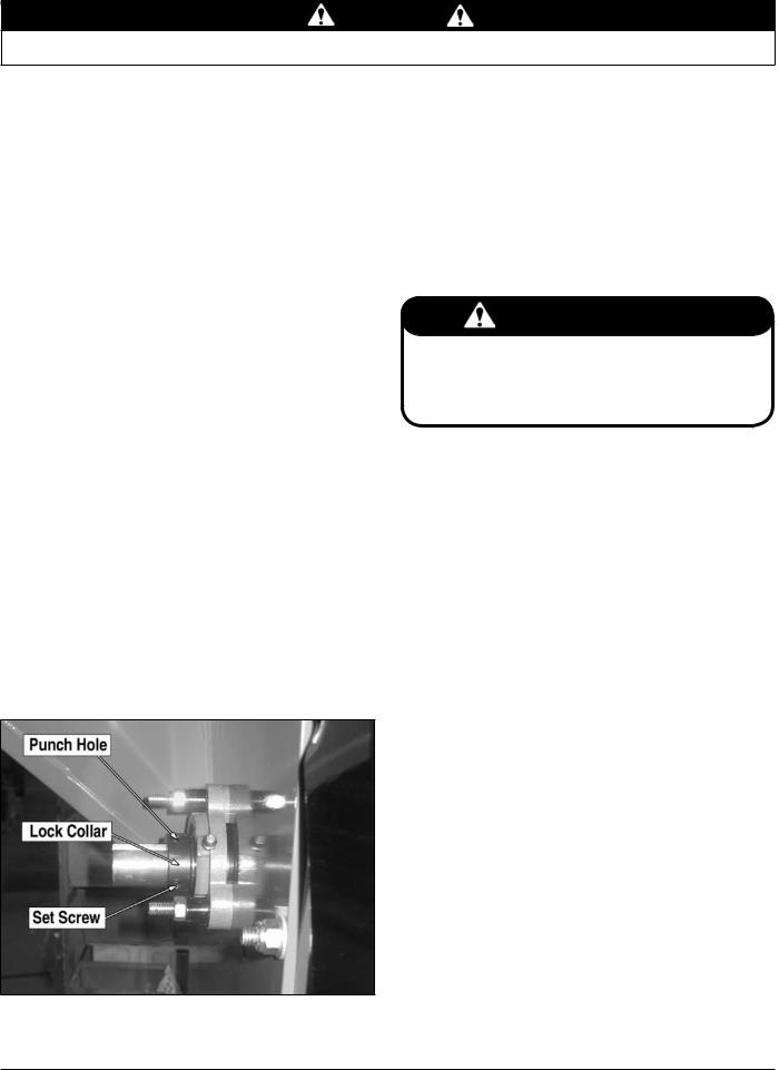
3.4 key switch
Models: All models
The key switch is used to start or stop the engine. See Figures 3.5 thru 3.8 for keyswitch locations. Refer to the engine manual for further operating instructions.
Figure 3.5
Honda On/Off switch
Figure 3.6
Honda Eectric
Key Switch
Figure 3.7
Briggs Electric
On/Off Switch
Figure 3.8
Briggs Commercial
On/Off Switch
3.5 shredder chute
Models: All models
Materials to be shredded are fed through the shredder chute to the shredder knives.
3.6 shredder knives
Models: All models
The shredder knives shred material that is fed into the shredder chute.
3.7 chipper chute
Models: All models
Materials to be chipped are fed through the chipper chute to the chipper blades.
3.8 chipper blades
Models: All models
The chipper blades chip material that is fed into the chipper chute.
3.9 jack stand
Models: 70580 & 70580S
Always have the jack stand retracted from the ground when moving the unit. When in use, be sure the jack stand is down and locked in position with the snap pin.
3 INCH CHIPPER/SHREDDERS |
13 |
 4
4 Operation
Section
As with any other piece of outdoor power equipment, getting the feel for how your machine operates and getting to know the best techniques for particular jobs are important to overall good performance.
chipping OPERATION
The chipping operation takes place on the right side of the machine, where hardened steel chipper blades are mounted on a rotating rotor assembly. Material fed into the chipper chute is sliced into small chips and propelled out through a discharge screen. The chips can be diverted into a container or onto the ground.
Shredding OPERATION
In this operation, hardened steel shredder knives grind up material fed into the shredder chute. The shredded material then leaves the shredder area by traveling through the discharge screen. The shredded material can be diverted into a container or onto the ground.
WARNING
Before operating your machine, be sure you read and understand all safety, controls and operating instructions in this Owner/Operators manual and on your machine. Failure to follow these instructions can result in serious injury or property damage.
4.Move throttle to full position.
5.Slowly push the engagement handle down to engage the chipper/shredder.
6.For a Cold Engine — Gradually return the choke control to the off position after the engine starts and warms up. The machine may be operated during the warm up period, but it may be necessary to leave the choke partially on until the engine warms up.
For a Warm Engine — Return choke to the off position as soon as engine starts.
4.2 Starting recoil models
Move the machine to a clear, level area outdoors before starting. Do not operate in the vicinity of bystanders. Make sure the cutting chamber is empty before starting.
1.Check engine oil level before starting.
2.Place the throttle control midway between the slow and fast positions. Place the choke control into the choke position.
3.Turn the key switch to on (if equipped). Pull the recoil starter until the engine starts. Make sure the starting cord retracts.
4.Move throttle to full position.
5.Slowly push the engagement handle down to engage the chipper/shredder.
4.1 Starting electric models
Move the machine to a clear, level area outdoors before starting. Do not operate in the vicinity of bystanders. Make sure the cutting chamber is empty before starting.
Do not crank the engine continuously for more than 10 seconds at a time. If the engine does not start, allow a 60 second cool down period between starting attempts. Failure to follow these guidelines can burn out, or permanently damage, the starter motor.
If the engine develops sufficient speed to disengage the starter but does not keep running (a false start), the engine rotation must be allowed to come to a complete stop before attempting to restart the engine. If the starter is engaged while the flywheel is rotating, damage to the starter may result.
If the starter does not turn the engine over, shut off starter immediately. Do not make further attempts to start the engine until the condition is corrected. Do not jump start using another battery. Follow the steps below to start the machine.
1.Check engine oil level before starting.
2.Place the throttle control midway between the slow and fast positions. Place the choke control into the choke position.
3.Start the engine by activating the key switch. Release the switch as soon as the engine starts.
For a Cold Engine — Gradually return the choke control to the off position after the engine starts and warms up. The machine may be operated during the warm up period, but it may be necessary to leave the choke partially on until the engine warms up.
For a Warm Engine — Return choke to the off position as soon as engine starts.
14 |
3 INCH CHIPPER/SHREDDERS |

OPERATION
4.3 Stopping the Chipper/Shredder
1.Move the throttle to the slow idle position.
2.Disengage the engagement handle.
3.Allow the engine to run at idle for 30-60 seconds; stop the engine by moving the throttle to the low position or turn off ignition.
4.Allow machine to come to a complete stop.
WARNING
Allow the machine to come to complete stop before inspection or servicing. The rotor is heavy and has inertia built up that will allow the rotor to turn for some time after the clutch has been disengaged. You can tell when the rotor has come to a complete stop when there is no noise or machine vibration present. You can reengage the clutch to slow the rotor to a stop.
4.4 Chipping Guide
The chipper chips a variety of materials into a more readily decomposed or handled condition. The following guidelines can help you get started.
1.Run unit at full operating speed before starting to chip material.
2.Select limbs that are up to 3 inches in diameter. Trim side branches that cannot be bent enough to feed into the chipper chute. Hold small diameter branches together in a bundle and feed in simultaneously.
3.Exclude pieces of metal, rocks, bottles, cans, and other foreign objects when feeding chipable material into the machine.
4.Feed brush from the side of the chipper chute, rather than from the front. Step aside to avoid being hit by the brush moving into the chipper.
5.Do not lean over the chipper chute to push objects into the cutting device. Use a push stick or brush paddle.
6.Never use shovels or forks to feed brush. They can be chipped, are expensive to replace, and cause extensive damage. In addition, metal pieces can be ejected from the chipper chute and cause serious injury or death.
7.Never feed brush into the chipper chute with your feet.
8.Place limb, butt end first, into the chipper chute until it contacts the chipper blades. The actual feed rate of the limb into the chipper will depend on the type of material fed and sharpness of the cutting blades.
9.Stop the material feeding and allow the engine to recover if the engine slows to where it may stall.
10.Remove the branch and rotate it before reinserting it into the chute if the chipper jams.
11.Alternately insert and retract the limb or insert continuously at a rate that will not kill the engine.
12.Chipping dead, dry material will create heat and dull the chipping blades quickly.
13.Alternate greener material with dry material to lubricate the chipping blades for longer life and better performance.
14.The chipping blades will become dull and will require periodic sharpening. Refer to the Service and Maintenance section for sharpening instructions.
4.5 shredding Guide
1.Place materials to be shredded (grass, leaves, garden refuse, sticks and branches less than 3/4 inch diameter and 24 inches long, etc.) into the hopper.
2.Exclude pieces of metal, rocks, bottles, cans, and other foreign objects when feeding chipable material into the machine.
3.Never use hands or feet to clear material that has built up inside the shredder chute.
4.Never use shovels or forks to feed brush. They can be chipped, are expensive to replace, and cause extensive damage. In addition, metal pieces can be ejected from the chipper chute and cause serious injury or death.
5.Feed material evenly into the shredder so that the engine does not bog down or the shredder becomes plugged.
6.Attempting to use the clutch to clear a plugged rotor will cause belt damage. Refer to the Service and Maintenance section for instruction on clearing a plugged rotor.
7.Branches or items that plug or cause the machine to stall should be fed in more evenly or put through the chipper chute.
8.Stop the material feeding and allow the engine to recover if the engine slows to where it may stall.
9.Alternate greener material with dry material to lubricate the shredder knives for longer life and better performance.
3 INCH CHIPPER/SHREDDERS |
15 |

 5
5 Service & Maintenance
Section
5.1 Maintenance Schedule
The items listed in the service and maintenance schedule are to be checked, and if necessary, corrective action taken. This schedule is designed for units operating under normal conditions. If the unit is operating in adverse or severe usage conditions it may be necessary for the items to be checked and serviced more frequently.
See engine owners manual for further maintenance and troubleshooting information.
SERVICE AND MAINTENANCE SCHEDULE
|
|
|
|
|
FREQUENCY |
|
|
|
||
|
MAINTENANCE |
BEFORE |
EVERY |
EVERY |
EVERY |
EVERY |
EVERY |
EVERY |
EVERY |
|
COMPONENT |
8 |
25 |
50 |
1500 |
||||||
REQUIRED |
EACH USE |
100 HRS |
200 HRS |
500 HRS |
||||||
|
HRS |
HRS |
HRS |
HRS |
||||||
|
|
|
|
|
|
|||||
ENGINE OIL |
CHECK OIL LEVEL |
|
|
|
|
|
|
|
|
|
FUEL TANK |
FILL |
|
|
|
|
|
|
|
|
|
AIR CLEANER |
CHECK & CLEAN 1 |
|
|
|
|
|
|
|
|
|
AIR INTAKE |
CLEAN 1 |
|
|
|
|
|
|
|
|
|
NUTS & BOLTS |
CHECK |
|
|
|
|
|
|
|
|
|
CHIPPER BLADES |
CHECK, SHARPEN IF |
|
|
|
|
|
|
|
|
|
NEEDED 3 |
|
|
|
|
|
|
|
|
||
|
|
|
|
|
|
|
|
|
||
PRE-CLEANER |
CLEAN 1 |
|
|
|
|
|
|
|
|
|
ELEMENT |
|
|
|
|
|
|
|
|
||
|
|
|
|
|
|
|
|
|
||
SHREDDER |
CHECK CONDITION |
|
|
|
|
|
|
|
|
|
KNIVES |
|
|
|
|
|
|
|
|
||
|
|
|
|
|
|
|
|
|
||
BELT/PULLEY |
CHECK |
|
|
|
|
|
|
|
|
|
ALIGNMENT |
|
|
|
|
|
|
|
|
||
|
|
|
|
|
|
|
|
|
||
BELT CONDITION |
CHECK |
|
|
|
|
|
|
|
|
|
TIRE PRESSURE |
CHECK |
|
|
|
|
|
|
|
|
|
ENTIRE MACHINE |
CLEAN |
|
|
|
|
|
|
|
|
|
ROTOR BEARING |
GREASE |
|
|
|
|
|
|
|
|
|
ENGINE OIL |
CHANGE 1 |
|
|
|
|
|
|
|
|
|
COOLING |
CLEAN 1 |
|
|
|
|
|
|
|
|
|
SHROUDS |
|
|
|
|
|
|
|
|
||
|
|
|
|
|
|
|
|
|
||
SPARK PLUG |
CHECK CONDITION |
|
|
|
|
|
|
|
|
|
AND GAP |
|
|
|
|
|
|
|
|
||
|
|
|
|
|
|
|
|
|
||
STARTER DRIVE |
SERVICE 2 |
|
|
|
|
|
|
|
|
|
SOLONOID SHIFT |
DISASSEMBLE AND |
|
|
|
|
|
|
|
|
|
STARTER |
CLEAN 2 |
|
|
|
|
|
|
|
|
|
FUEL FILTER |
REPLACE |
|
|
|
|
|
|
|
|
|
BATTERY |
CHECK |
|
|
|
|
|
|
|
|
|
CONNECTIONS |
|
|
|
|
|
|
|
|
||
|
|
|
|
|
|
|
|
|
||
1Perform more frequently in dusty, dirty or severe usage conditions.
2Have a Briggs or Honda engine service dealer perform this service.
3It is a good sign that your chipper blades need sharpening when material stops self feeding.
16 |
3 INCH CHIPPER/SHREDDERS |
SERVICE & MAINTENANCE
 WARNING
Before inspecting or servicing any part of this machine, shut off power source,
disconnect spark plug wire from spark plug and make sure all moving parts have come to a complete stop.
5.2 Chipper Blades
WARNING
Chipping blades and shredder knives are sharp! Use caution when working on machine to avoid injury.
The chipper blades will eventually become dull, making chipping difficult and adding extra strain on the machine. Poor chipping performance is usually a result of dull chipping blades. It is recommended that the blades be sharpened every 5 - 15 hours or if your chipper’s performance has decreased. Check for the following symptoms and sharpen the blades if needed.
1.Severe vibration when feeding material into the chipper.
2.Small diameter branches do not self-feed.
3.Chips discharge unevenly or have stringy tails, especially when chipping green branches.
Before you sharpen the chipping blades, check for permanent damage. Replace the blade if:
1.There are cracks, broken corners or nicks greater than 1/8" (Figure 5.1).
2.The base of the cutting edge is worn or has been re-sharp- ened so that it sits too close to the rotor chipping slot.
1/8" |
Figure 5.1 - Causes for Replacement
5.2.1 Removing The Blades
1.Flip the discharge door up. For "S" models, remove the discharge assembly.
2.Remove the 5/16" x 7/8" bolt and nylock nut holding the shredder screen to the bottom of the frame.
3.Disconnect and remove the shredder screen from the machine.
4.Remove the two 5/16" x 1-1/2" hex bolts securing the chipper blade to the rotor. Repeat for the second blade.
5.Inspect blades to see if cracks or nicks are visible. If cracks are present, replace the blades. If nicks can not be removed by sharpening blade, replace the blade.
5.2.2 Sharpening the Blades
1.Never sharpen or grind the mounting surfaces of the blades. This will cause the edge to roll and the blade will be damaged, resulting in poor chipping performance.
2.Regrind the angled edge of the chipping blades to 45 degrees (Figure 5.2).
3.The blades can be ground on a bench grinder or by a professional.
4.Makesuresometypeoffixtureisusedtocorrectlyholdtheblade at the proper angle.
5.Be careful when grinding so that the blade does not become overheated and change color. This will remove the heattreated properties.
6.Use short grinding times and cool with water or some type of liquid coolant.
7.Remove an equal amount off each blade to maintain rotor balance.
8.Small imperfections such as nicks and burrs on the flat side of the blade will not affect the chipping performance of the machine.
9.For blades that have been repeatedly sharpened, ensure that the sharpened surface extends past the chipping slot opening. If it does not extend past the opening, the blades should be replaced.
|
|
MOUNTING SURFACE |
|
|
DO NOT GRIND |
45° |
|
SHARPENED |
|
SURFACE |
|
|
.25 |
|
|
SHARPENED |
MOUNTING SURFACE |
|
SURFACE |
|
|
DO NOT GRIND |
|
|
|
Figure 5.2 - Double Edged Blade
5.2.3 installing the blades
1.Place a blade on the rotor and attach with two 5/16" x 1-1/2" bolts. Torque to 25 Ft-lb. Repeat for the second blade.
2.Attach the shredder screen to the machine with one 5/16" x 7/8" bolt and nylock nut.
3.Lower the discharge door into the normal operating position. For "S" models, reinstall the discharge assembly.
3 INCH CHIPPER/SHREDDERS |
17 |
SERVICE & MAINTENANCE
WARNING
Before inspecting or servicing any part of this machine, shut off power source,
disconnect spark plug wire from spark plug and make sure all moving parts have come to a complete stop.
5 . 3 S e t t i n g C h i p p i n g B l a d e Clearance
The chipping blades should clear the chipper block, located inside the frame on the bottom edge of the chipper chute intake, by 1/16" to 1/8". To adjust the blade clearance, proceed as follows:
1.Remove the rotor shaft end cap and upper shield.
2.Loosen the set screws holding the lock collars on the chute side and engine side bearings (Figure 5.3).
3.Use a punch and hammer to tap the lock collars in the opposite direction of normal rotation. On the chute side bearing, tap punch in a CW rotation. On the engine side bearing, tap punch in a CCW rotation
4.Using a rubber mallet tap the end of the rotor shaft to obtain 1/16" to 1/8" clearance. Rotate the rotor and check the clearance on all chipping blades.
5.Once clearance has been set, the lock collars must be replaced and retightened. Using a punch and a hammer, tap the lock collars in the direction of shaft rotation (clockwise on the engine side bearing and counterclockwise on the chute side bearing) and set them with a hammer tap. Tighten the lock collar set screws.
6.Loosen the set screws holding the belt pulley on the rotor shaft. Move the pulley on the shaft so it is aligned with the engine drive pulley. The pulley should be moved the same amount the rotor was moved, only in the opposite direction. Torque pulley set screw to 160 In-lbs.
7.Insure the pulley drive key is completely seated under the pulley and tighten the set screws.
8.Check pulley alignment by laying a straightedge across the pulley faces. Pulley faces should line up. If not, repeat steps 6 and 7 until the pulley is lined up.
5.4 Replacing the shredder knives
The Rectangular Shredder Knife Kit is a replacement kit to replace existing dull or damaged knives. The serrated shredder knives are designed to offer long life and can be reversed if they become dull. This shredder kit uses an improved knife pattern to provide more complete shredding, durability, and easier feeding. Ensure the knives and spacers are properly installed to maintain rotor balance.
Refer to the Parts Manual for shredder knife kit. To remove the knives or to install a new shredder kit proceed as follows.
IMPORTANT
The serrated edge of the shredder knives should face the same direction as the cutting edge of the chipper blades. Never reuse the #10-24 nut and bolt. Never reuse shafts or spacers if they show signs of wear or abuse. Always install new parts when repairing.
1.Remove the lower belt guard from under engine frame, remove discharge door and discharge screen.
2.Remove the 10-24 x 1-3/8" bolts and nuts from knife shafts.
3.Align shaft with the 5/8" hole in rear of frame and the small hole in front of frame by the chipper chute.
4.Using a small punch or rod, push the shaft out the 5/8" hole in rear of frame.
5.To assemble, insert shaft through the 5/8" hole in rear of frame and slide knives and spacers in their proper order onto the shaft. Install a new 10-24 x 1-3/8" bolt and nut.
6.Repeat steps 3 through 6 to assemble the other three shafts.
7.When completed, install the discharge screen, discharge door and torque all 3/8" bolts to 33 Ft-lbs. Test run machine.
Figure 5.3 - Lock Collar
18 |
3 INCH CHIPPER/SHREDDERS |
SERVICE & MAINTENANCE
 WARNING
Before inspecting or servicing any part of this machine, shut off power source,
disconnect spark plug wire from spark plug and make sure all moving parts have come to a complete stop.
5.5 changing the discharge screen
There are several optional discharge screens available in different sizes. Different size discharge screens produce different size chips. To change the discharge screen proceed as follows:
1.Lift discharge door to gain access to the discharge screen.
2.Remove the 5/16" x 7/8" bolt and nut securing the discharge screen to the frame (Figure 5.4).
3.Pull discharge screen out from the bottom and rotate the top down.
4.Clean any trash or debris out from the screen area.
5.Insert the top of the replacement screen into the slot in the chipper body and push the bottom of the screen inward so bolt holes align.
6.Install the bolt from the underside upward through the frame and screen, attach nut and tighten to specified torque.
5.6 Belt guide adjustments
The belt guide aids in disengaging the chipper/shredder. If problems arise with engaging and disengaging the unit, follow the instructions below. These instructions also adjust the lower belt guard.
1.Remove upper shield to expose the belt and pulleys.
2.Loosen set screws and using a straightedge align the engine pulley with the idler pulley and the rotor pulley with the engine pulley. Tighten all set screws.
3.Engage the clutch with the belt in place and check idler engagement. The idler pulley should impact the belt in the center of the pulley. All pulleys must be in perfect alignment. Torque pulley set screws to 160 In-lbs.
4.If idler pulley will not remain in alignment with engine and rotor pulleys, it may be necessary to replace the idler bracket bushings. Contact the ECHO Bear Cat service department for more information.
5.There should be 1/8" clearance between the belt and the lower belt guard when the clutch is engaged. Adjust by loosening the mounting bolts and repositioning the guide. Retighten mounting bolts.
6.Reinstall upper shield.
7.From underneath, check the alignment of lower belt guard with a post card (Figure 5.5). With the clutch engaged, there should be enough room between the belt and the side of the guard for the card to slide along the belt. With the clutch disengaged, the card should not be able to slide. Adjust if necessary.
Figure 5.4 - Replacing the Discharge Screen
Figure 5.5 - Belt Guide Adjustments
3 INCH CHIPPER/SHREDDERS |
19 |

SERVICE & MAINTENANCE
WARNING
Before inspecting or servicing any part of this machine, shut off power source,
disconnect spark plug wire from spark plug and make sure all moving parts have come to a complete stop.
5.7 remove/Replace Drive Belt
Check the condition of the drive belts annually or every 50 hours of operation, whichever comes first. Replace the belt if cracked, frayed or worn. To replace the belt, proceed as follows:
1.Remove the upper shield, upper belt guide and lower belt guard.
2.Remove idler pulley.
3.Slip the drive belt off the belt pulleys.
4.Inspect pulleys for wear. Replace the pulleys if they are cracked or worn so that the belt contact area is not smooth and flat.
5.Place the new belt over pulleys. Do not force or pry the belt over pulleys as this may cause cord breakage.
6.Reinstall the idler pulley.
7.Check alignment (Section 5.6).
8.Replace all shields, guides and guards.
5.10 Trailer Service Tips
1.Check wheel bolt torque every 8 hours of towing use.
2.Check air pressure in tire every 8 hours. Fill to the recommended PSI located on the tire sidewall.
3.Check and repack wheel bearings with grease every year.
5.8 Clearing a plugged rotor
1.Remove the bolt securing the discharge screen to the frame and remove the shredder screen.
2.Clean the debris out of the shredding rotor and/or chipper discharge area and tube. Turn the rotor by hand to be sure it is free to rotate.
3.Install discharge screen and retaining bolt.
5.9 Removing Rotor
1.Remove discharge cover, screen and rotor shaft end cap.
2.Loosen the set screws on the lock collar securing the chute side bearing on the rotor shaft.
3.Using a punch and hammer, tap the lock collar in the opposite direction of normal rotation until loose; remove lock collar and bearing.
4.Remove the upper shield, upper belt guide and lower belt guard to allow access to the engine side bearing.
5.Remove the drive belt (Section 5.7).
6.Loosen the set screws holding the belt pulley on the rotor shaft and remove the pulley.
7.Repeat steps 2 and 3 on the engine side rotor bearing.
8.Remove the bolts securing the chipper chute cover to the frame and remove chipper chute cover.
9.Remove rotor.
20 |
3 INCH CHIPPER/SHREDDERS |
SERVICE & MAINTENANCE
 WARNING
Before inspecting or servicing any part of this machine, shut off power source,
disconnect spark plug wire from spark plug and make sure all moving parts have come to a complete stop.
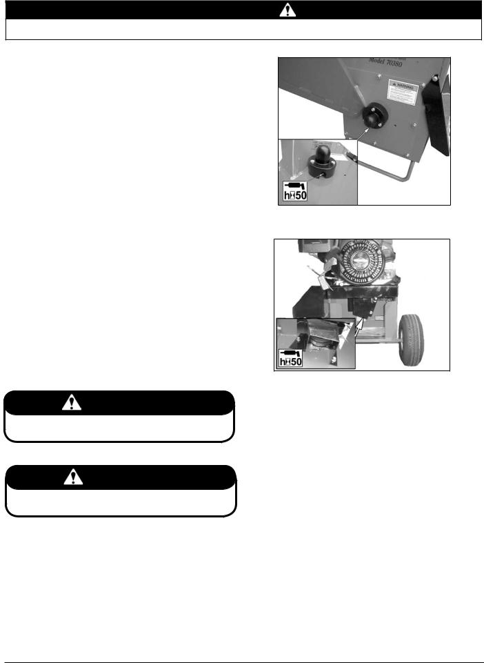
5.11 greaseable Bearings and Pivots
Mounted Unit ball bearings (referred to as “Insert Bearings) are pre-lubricated at our factory and are ready for operation.
Re-lubrication: Re-lubrication of insert bearings is determined by operating conditions and environment. Relubricate standard bearings with a LITHIUM based grease.
Greasing Intervals: Bearings in extreme environments will require more frequent greasing intervals.
Grease Fill Amounts: It is preferred that experience dictate fill amounts due to wide variances in applications, greasing equipment and operating conditions. The quantities shown in the pictures are recommended amounts. In most cases, it is best to relube in small amounts, under low pressure, until a thin bead of fresh grease is visible at the seal lip area.
Care should be taken when re-greasing bearings to avoid overfilling. Overfilling can lead to excessive heat and or unseating of the seals. Grease should be introduced in small increments and under light pressure. Whenever possible, the bearing should be rotated slowly while grease is being added to ensure equal distribution throughout the raceways.
The chipper models described in this manual have two (2) greaseable bearings and pivots that require greasing. Refer to pictures for greasing intervals and quantities.
1.Chute side bearing (Figure 5.6).
2.Engine side bearing (Figure 5.7).
Figure 5.6 - Chute Side Bearing.
Figure 5.7 - Engine Side Bearing.
NOTE
Polyuria and lithium based greases are not compatible. Mixing the two grease types may lead to premature failure.
NOTE
The use of pneumatic grease equipment is not recommended unless low pressure is assured.
3 INCH CHIPPER/SHREDDERS |
21 |

 6
6 Troubleshooting
Section
Before performing any of the corrections in this troubleshooting chart, refer to the appropriate information contained in this manual for the correct safety precautions and operating or maintenance procedures. Contact your nearest dealer or the factory for service problems with the machine.
PROBLEM |
|
POSSIBLE CAUSE |
|
REMEDY |
|
|
1. |
Improper control settings. |
1. |
Use proper settings. |
|
|
2. |
Fill fuel tank. |
|||
|
2. |
Lack of fuel. |
|||
|
3. |
Connect spark plug. |
|||
Engine will not start. |
3. |
Spark plug disconnected. |
|||
4. |
Refill gas tank with fresh, clean unleaded regular gaso- |
||||
|
4. |
Dirty, stale or contaminated gas. |
|||
|
|
line. |
|||
|
5. |
Internal engine problems. |
|
||
|
5. |
See your dealer. |
|||
|
|
|
|||
|
1. |
Obstructed discharge. |
1. |
Use branch or similar object to clear discharge. |
|
Engine or rotor stalls or stops. |
2. |
Plugged rotor. |
2. |
Clear rotor. Feed material more evenly. |
|
|
3. |
Feeding material too large into shredder. |
3. |
Reduce size of material being fed into shredder. |
|
Engine overheats. |
1. |
Cooling system plugged. |
1. |
Clean cooling fan and fins. |
|
2. |
Fill engine to correct oil level. Refer to the engine own- |
||||
2. |
Improper oil level. |
||||
|
|
ers manual. |
|||
|
|
|
|
||
|
1. |
Dull chipper blades. |
1. |
Reverse or sharpen blades. |
|
Hard to feed chipper; requires |
2. |
Use branch or similar object to clear discharge. |
|||
2. |
Obstructed discharge. |
||||
excessive power to chip. |
3. |
Adjust clearance between chipper block and chipper |
|||
3. |
Improper blade clearance. |
||||
|
|
blades. |
|||
|
|
|
|
||
|
|
|
|
|
|
|
1. |
Obstructed discharge. |
1. |
Use branch or similar object to clear discharge. |
|
Shredder requires excessive |
2. |
Clear rotor, feed material into shredder more evenly. |
|||
2. |
Plugged rotor. |
||||
power or stalls. |
3. |
Alternately feed dry material or install larger discharge |
|||
3. |
Wet or green material will not discharge. |
||||
|
|
screen. |
|||
|
|
|
|
||
|
|
|
|
|
|
Engine stalls or belt squeals |
1. |
Engaging clutch too fast. |
1. |
Lower engagement handle more slowly. |
|
2. |
Plugged rotor. |
2. |
Clear rotor. Feed material more evenly. |
||
when engaging clutch. |
|||||
3. |
Belt tension too loose. |
3. |
Replace belt or spring. |
||
|
|||||
|
1. |
Stringy, green material bypasses chipper |
1. |
Rotate branch or material when feeding to cut com- |
|
|
|
pletely. |
|||
Material from chipper wraps |
|
blades. |
|
||
|
2. |
Sharpen blades. |
|||
around rotor shaft. |
2. |
Dull chipper blades. |
|||
3. |
Adjust clearance between chipper block and chipper |
||||
|
3. |
Improper blades clearance. |
|||
|
|
blades. |
|||
|
|
|
|
||
|
|
|
|
|
|
|
1. |
Drive system vibration. |
1. |
Check drive belts and pulleys for bad or worn areas. Check |
|
|
|
for dull chipper blades or shredder knives. |
|||
|
2. |
Rotor out of balance. |
2. |
Inspect rotor for broken or missing chipper blades and |
|
Excessive vibration while running. |
|
shredder knives; replace if needed. Check rotor to see if |
|||
|
|
|
|||
|
3. |
Chipper blade to chipper block clearance is |
|
it wobbles. Check to see if rotor is assembled correctly. |
|
|
|
incorrect. |
3. |
Set chipper blade/block clearance to recommended dis- |
|
|
|
|
|
tance (1/16" to 1/8"). |
|
|
1. |
Drive belt too loose or broken. |
1. |
Replace belt or spring. |
|
Rotor will not turn. |
2. |
Obstructed discharge. |
2. |
Use branch or similar object to clear discharge. |
|
|
3. |
Plugged rotor. |
3. |
Clear rotor. Feed material more evenly. |
|
|
|
|
|
|
|
|
1. |
Improper belt installation; belt not under belt |
1. |
Install belt properly; install belt under belt guide. |
|
Cannot engage clutch. |
|
guide. |
|||
|
|
2. |
Replace belt or spring. |
||
|
2. |
Improper belt tension. |
|||
|
|
|
|||
|
|
|
|
|
|
|
1. |
Not using correct belt. |
1. |
Contact your nearest authorized dealer to order the correct |
|
|
|
belt for your chipper/shredder. |
|||
|
|
|
|
||
Excessive belt wear. |
2. |
Pulley(s) damaged or worn. |
2. |
Replace pulley(s). |
|
|
|
||||
3. |
Pulley(s) not in alignment. |
|
|
||
|
3. |
Align pulley(s) with straight edge. |
|||
|
|
|
|||
|
4. |
Belt(s) tension too loose. |
4. |
Replace belt or spring. |
|
|
|
|
|||
Trailer sways during towing. |
1. |
Tire air pressure not correct |
1. |
Check tire sidewall for inflation limits. |
|
|
|
|
|
|
22 3 INCH CHIPPER/SHREDDERS
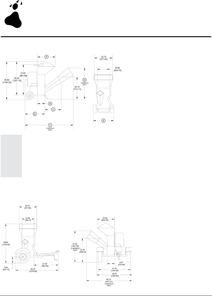
 7
7 Specifications
Section
7.1 non-towable models
|
|
|
|
MEASUREMENT |
|
|
|
||
MODEL |
|
|
|
|
IN [MM] |
|
|
|
|
|
A |
B |
C |
|
D * |
|
E |
F * |
G |
|
|
|
|
|
|
|
|
|
|
70050 (S) |
22.16 |
6.67 |
15.34 |
|
43.25 |
|
23.98 |
51.00 |
21.32 |
[562.86] |
[169.42] |
[389.64] |
|
[1098.55] |
|
[609.09] |
[1295.40] |
[541.53] |
|
|
|
|
|||||||
70080 (S) |
|
|
|
|
|
|
|
|
|
70085 |
24.44 |
9.27 |
20.04 |
|
44.48 |
|
23.75 |
54.00 |
25.61 |
70180 (S) |
|
|
|||||||
[620.78] |
[235.46] |
[509.02] |
|
[1129.79] |
|
[603.25] |
[1371.60] |
[650.49] |
|
70380 (S) |
|
|
|||||||
|
|
|
|
|
|
|
|
|
|
70385 |
|
|
|
|
|
|
|
|
|
|
|
|
|
|
|
|
|
|
|
* S MODELS ONLY |
|
|
|
|
|
|
|
|
|
|
|
|
|
|
|
|
|
|
|
7.2 towable models
3 INCH CHIPPER/SHREDDERS |
23 |
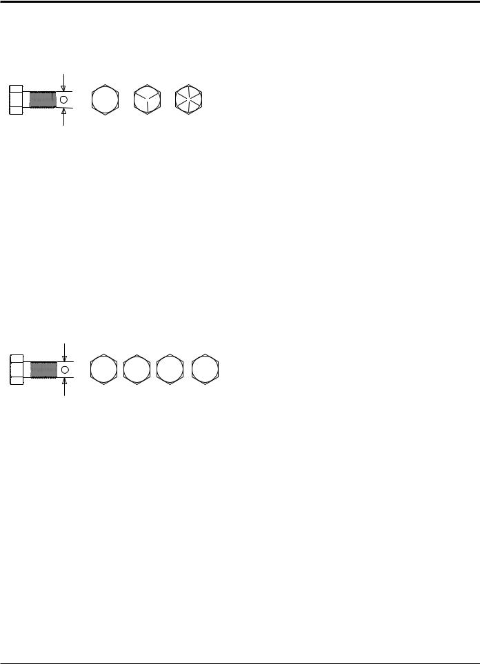
SPECIFICATIONS
7.3 bOLT torque
The tables below are for reference purposes only and its use by anyone is entirely voluntary, unless otherwise noted. Reliance on its contents for any purpose is at the sole risk of that person. ECHO Bear Cat is not responsible for any loss or damage resulting from the use of this information. In developing these tables, ECHO Bear Cat has made a determined effort to present the contents accurately.
SAE - 2 SAE - 5 SAE - 8
A
|
|
|
|
ENGLISH |
|
|
|
BOLT DIAMETER |
|
|
|
BOLT TORQUE * |
|
|
|
(A) |
|
SAE 2 |
SAE 5 |
SAE 8 |
|||
|
N.m |
|
Ft-lb. |
N.m |
Ft-lb. |
N.m |
Ft-lb. |
1/4" |
7.5 |
|
5.5 |
11 |
8 |
16 |
12 |
5/16" |
15 |
|
11 |
23 |
17 |
34 |
25 |
3/8" |
27 |
|
20 |
41 |
30 |
61 |
45 |
7/16" |
41 |
|
30 |
68 |
50 |
95 |
70 |
1/2" |
68 |
|
50 |
102 |
75 |
149 |
110 |
9/16" |
97 |
|
70 |
149 |
110 |
203 |
150 |
5/8" |
122 |
|
90 |
203 |
150 |
312 |
230 |
3/4" |
217 |
|
160 |
353 |
260 |
515 |
380 |
7/8" |
230 |
|
170 |
542 |
400 |
814 |
600 |
1" |
298 |
|
220 |
786 |
580 |
1220 |
900 |
1-1/8" |
407 |
|
300 |
1085 |
800 |
1736 |
1280 |
1-1/4" |
570 |
|
420 |
2631 |
1940 |
2468 |
1820 |
A |
|
|
|
4.8 |
8.8 |
10.9 |
12.9 |
|
|
|
|
|
|
METRIC |
|
|
|
|
|
|
BOLT DIAMETER |
|
|
|
|
|
BOLT TORQUE * |
|
|
|
|
|
|
(A) |
|
4.8 |
8.8 |
|
|
10.9 |
|
12.9 |
||||
|
N.m |
|
Ft-lb. |
N.m |
|
Ft-lb. |
N.m |
|
Ft-lb. |
N.m |
|
Ft-lb. |
M3 |
0.5 |
|
0.4 |
- |
|
- |
- |
|
- |
- |
|
- |
M4 |
3 |
|
2.2 |
- |
|
- |
- |
|
- |
- |
|
- |
M5 |
5 |
|
4 |
- |
|
- |
- |
|
- |
- |
|
- |
M6 |
6 |
|
4.5 |
11 |
|
8.5 |
17 |
|
12 |
19 |
|
14.5 |
M8 |
15 |
|
11 |
28 |
|
20 |
40 |
|
30 |
47 |
|
35 |
M10 |
29 |
|
21 |
55 |
|
40 |
80 |
|
60 |
95 |
|
70 |
M12 |
50 |
|
37 |
95 |
|
70 |
140 |
|
105 |
165 |
|
120 |
M14 |
80 |
|
60 |
150 |
|
110 |
225 |
|
165 |
260 |
|
190 |
M16 |
125 |
|
92 |
240 |
|
175 |
350 |
|
255 |
400 |
|
300 |
M18 |
175 |
|
125 |
330 |
|
250 |
475 |
|
350 |
560 |
|
410 |
M20 |
240 |
|
180 |
475 |
|
350 |
675 |
|
500 |
800 |
|
580 |
M22 |
330 |
|
250 |
650 |
|
475 |
925 |
|
675 |
1075 |
|
800 |
M24 |
425 |
|
310 |
825 |
|
600 |
1150 |
|
850 |
1350 |
|
1000 |
M27 |
625 |
|
450 |
1200 |
|
875 |
1700 |
|
1250 |
2000 |
|
1500 |
* Torque value for bolts and capscrews are identified by their head markings.
Torque figures indicated above are valid for non-greased or non-oiled threads and heads unless otherwise specified. Therefore, do not grease or oil bolts or capscrews unless otherwise specified in this manual. When using locking elements, increase torque values by 5%.
24 |
3 INCH CHIPPER/SHREDDERS |
 Loading...