

Page 1

WHEELED
TRIMMER
WT24 - 190cc SUBARU - PUSH
WT24T - 190cc SUBARU - PUSH with TILT
WT24S - 190cc SUBARU - SELF-PROPELLED
ENGLISH ESPAÑOL FRANÇAIS
PN: 77298-00
Rev. 010113
Companion to 77297-00
SN Range: C08287 to D03241
OWNER'S MANUAL
Page 2

Before You Begin
DEAR ECHO BEAR CAT CUSTOMER
Thank you for purchasing a ECHO Bear Cat product. The ECHO Bear Cat line is designed, tested, and manufactured
to give years of dependable performance. To keep your machine operating at peak efciency, it is necessary to adjust
it correctly and make regular inspections. The following pages will assist you in the operation and maintenance of your
machine. Please read and understand this manual before operating your machine.
If you have any questions or comments about this manual, please call us toll-free at 1.888.645.4520.
If you have any questions or problems with your machine, please call or write your local authorized ECHO Bear Cat Dealer.
This document is based on information available at the time of its publication. ECHO Bear Cat is continually making
improvements and developing new equipment. In doing so, we reserve the right to make changes or add improvements
to our product without obligation for equipment previously sold.
PLEASE SEND US YOUR WARRANTY CARD
A warranty card is included in your owner's kit packaged with your machine. Please take the time to ll in the information
requested on the card. When you send your completed card to us, we will register your machine and start your coverage
under our limited warranty or go to bearcatproducts.com/warranty/warranty-registration/.
FOR MACHINE SERVICE OR PARTS:
For service assistance, contact your nearest authorized
ECHO Bear Cat dealer or the factory. For parts, contact
your authorized dealer. The parts manual for your machine
is available at http://bearcatproducts.com/main/support/
index_html. Your dealer will need to know the serial number
of your machine to provide the most efcient service. See
below for information on how to identify and record the
serial number for your machine.
FOR ENGINE SERVICE OR PARTS:
For engine service or parts, contact your nearest authorized
engine dealer. ECHO Bear Cat does not handle any parts,
repairs or warranties for engines.
SERIAL NUMBER LOCATION
Please record the serial number in the space provided and
on the warranty and registration card.
MANUFACTURED BY CRARY INDUSTRIES
WEST FARGO, NORTH DAKOTA 58078 U.S.A.
SERIAL NUMBER
MANUFACTURED IN U.S.A.
XXXXXX
ORDERING PARTS
Only genuine ECHO Bear Cat replacement parts should
be used to repair the machine. Replacement parts
manufactured by others could present safety hazards,
even though they may t on this machine. Replacement
parts are available from your ECHO Bear Cat dealer.
Provide the following when ordering parts:
The SERIAL NUMBER of your machine.
The PART NUMBER of the part.
The PART DESCRIPTION.
The QUANTITY needed.
SERIAL NUMBER
HOW TO CONTACT ECHO BEAR CAT
ADDRESS PHONE E-MAIL HOURS
237 NW 12th Street
P.O. Box 849
West Fargo, ND 58078
*Original Instructions
© 2013, CRARY INDUSTRIES, ALL RIGHTS RESERVED. PRODUCED AND PRINTED IN THE U.S.A.
888.645.4520
701.282.5520
FAX: 701.282.9522
sales@bearcatproducts.com
service@bearcatproducts.com
Monday - Friday,
8 am to 5 pm
Central Time
Page 3

LIMITED WARRANTY
This warranty applies to all ECHO Bear Cat Outdoor Power Equipment manufactured by Crary Industries Inc.
Crary Industries warrants to the original owner each new ECHO Bear Cat product to be free from defects in
material and workmanship, under normal use and service. The warranty shall extend, from date of purchase, 3
years (U.S. and Canada only (2 years outside U.S. and Canada)) for Consumer use of the product, 1 year for
Commercial applications and 6 months for Rental applications.
“Consumer” defined as: complete unit for personal, residential or non-income producing use.
“Commercial” defined as: complete unit for commercial, institutional, property management, agricultural,
horticultural or income producing use.
“Rental” defined as: complete unit for rental purposes to produce income.
*Models SC2170, SC2206 & SC3206 are classified as Consumer grade products and will not qualify for warranty
coverage if used for Commercial or Rental purposes.
The product is warranted to the original owner as evidenced by a completed warranty registration on file at Crary
Industries. Replacement parts are warranted for (90) days from date of installation.
THE WARRANTY REGISTRATION MUST BE COMPLETED AND RETURNED TO CRARY INDUSTRIES
WITHIN 10 DAYS OF DELIVERY OF THE PRODUCT TO THE ORIGINAL OWNER OR THE WARRANTY
WILL BE VOID.
In the event of a failure, return the product, at your cost, along with proof of purchase to the selling ECHO Bear
Cat dealer. Crary Industries will, at its option, repair or replace any parts found to be defective in material or
workmanship. Warranty on any repairs will not extend beyond the product warranty. Repair or attempted repair
by anyone other than an authorized ECHO Bear Cat dealer as well as subsequent failure or damage that may
occur as a result of that work will not be paid under this warranty. Crary Industries does not warrant replacement
components not manufactured or sold by Crary Industries.
ENGLISH
1. This warranty applies only to parts or components that are defective in material or workmanship.
2. This warranty does not cover normal wear items including, but not limited to: bearings, belts, pulleys, filters,
chipper blades, shredder flails or knives.
3. This warranty does not cover normal maintenance, service or adjustments.
4. This warranty does not cover depreciation or damage due to misuse, negligence, accident or improper
maintenance.
5. This warranty does not cover damage due to improper setup, installation or adjustment.
6. This warranty does not cover damage due to unauthorized modifications of the product.
7. Engines are warranted by the respective engine manufacturer and are not covered by this warranty.
Crary Industries is not liable for any property damage, personal injury or death resulting from the unauthorized
modification or alteration of an ECHO Bear Cat product or from the owner’s failure to assemble, install, maintain
or operate the product in accordance with the provisions of the Owner’s manual.
Crary Industries is not liable for indirect, incidental or consequential damages or injuries including but not limited
to loss of crops, loss of profits, rental of substitute equipment or other commercial loss.
This warranty gives you specific legal rights. You may have other rights that may vary from area to area.
Crary Industries makes no warranties, representations or promises, expressed or implied as to the performance
of its products other than those set forth in this warranty. Neither the dealer nor any other person has any authority
to make any representations, warranties or promises on behalf of Crary Industries or to modify the terms or
limitations of this warranty in any way. Crary Industries, at its discretion, may periodically offer limited, written
enhancements to this warranty.
CRARY INDUSTRIES RESERVES THE RIGHT TO CHANGE THE DESIGN AND/OR SPECIFICATIONS OF
ITS PRODUCTS AT ANY TIME WITHOUT OBLIGATION TO PREVIOUS PURCHASERS OF ITS PRODUCTS.
Page 4

TABLE OF CONTENTS
DESCRIPTION PAGE
SAFETY ................................................................................................................1
1.1 SAFETY ALERT SYMBOL .....................................................................................1
1.2 EMISSION INFORMATION ....................................................................................1
1.3 BEFORE OPERATING ...........................................................................................2
1.4 OPERATIION SAFETY ..........................................................................................2
1.5 MAINTENANCE AND STORAGE SAFETY ...........................................................2
1.6 SAFETY DECAL LOCATIONS ...............................................................................3
ASSEMBLY ........................................................................................................... 4
2.1 ADJUST THE HANDLEBAR ..................................................................................4
2.2 ADD OIL 4
2.3 FILL THE FUEL TANK ............................................................................................4
FEATURES & CONTROLS ................................................................................... 5
OPERATION ......................................................................................................... 6
4.1 STARTING THE TRIMMER ....................................................................................6
4.2 STOPPING THE TRIMMER ...................................................................................6
4.3 TRIMMING GUIDE .................................................................................................6
4.4 WT24 — OFF-SET TRIMMING ..............................................................................7
4.5 WT24T — TILT & TRIM FEATURE ........................................................................7
4.6 WT24S — SELF-PROPELLED OPERATION .......................................................7
SERVICE & MAINTENANCE ................................................................................8
5.1 MAINTENANCE SCHEDULE.................................................................................8
5.2 ENGINE MAINTENANCE ......................................................................................8
5.3 CUTTING STRING REPLACEMENT .....................................................................9
5.4 CUTTING HEIGHT ADJUSTMENT ........................................................................9
5.5 WT24S — TRANSMISSION ADJUSTMENT .......................................................10
TRIMMER BAIL ADJUSTMENT ..................................................................................10
5.6 WT24 AND WT24T CUTTING HEAD DRIVE BELT REPLACEMENT .................11
5.7 WT24S CUTTING HEAD DRIVE BELT REPLACEMENT ....................................13
5.8 WT24S — DRIVE CHAIN ADJUSTMENT ............................................................15
5.9 WT24S TRANSMISSION BELT REPLACEMENT ...............................................16
TROUBLESHOOTING ........................................................................................ 17
SPECIFICATIONS ............................................................................................... 18
BOLT TORQUE ...........................................................................................................19
OPTIONS ............................................................................................................ 20
Page 5

1
Section
SAFETY
1.1 SAFETY ALERT SYMBOL 1.2 EMISSION INFORMATION
Under California
Law and the laws of
several other states,
you are not permitted
to operate an internal
combustion engine using
hydrocarbon fuels on any
forest covered, brush
covered or grass covered
The Owner/Operator’s manual uses this symbol to alert
you of potential hazards. Whenever you see this symbol,
read and obey the safety message that follows it. Failure
to obey the safety message could result in personal injury,
death or property damage.
DANGER
Indicates an imminently hazardous situation that, if not
avoided, will result in death or serious injury.
WARNING
Indicates a potentially hazardous situation that, if not
avoided, could result in death or serious injury.
land or on land covered with grain, hay or other ammable
agricultural crops, without an engine spark arrester in
continuous effective working order.
The engine on your power equipment, like most outdoor
power equipment, is an internal combustion engine that
burns gasoline or diesel fuel (hydrocarbons). Therefore,
your power equipment must be equipped with a spark
arrester mufer in continuous effective working order. The
spark arrester must be attached to the engine exhaust
system in such a manner that ames or heat from the
system will not ignite ammable material.
Failure of the owner/operator of the equipment to comply
with this regulation is a misdemeanor under California law
and may also be a violation of other state and/or federal
regulations, laws, ordinances, or codes. Contact your
local re marshal or forest service for specic information
about which regulations apply in your area.
ENGLISH
CAUTION
Indicates a potentially hazardous situation that, if not
avoided, may result in minor or moderate injury.
WHEELED TRIMMER
The standard mufer installed on the engine is not equipped
with a spark arrester. One must be added before using
this machine in an area where a spark arrester is required
by law. Contact the local authorities if these laws apply to
you. See your authorized engine dealer for spark arrester
options.
1
Page 6

SAFETY
1.3 BEFORE OPERATING
1. Read and understand this owner’s manual. Be
completely familiar with the controls and the proper
use of this equipment.
2. Familiarize yourself with all of the safety and operating
decals on this equipment and on any of its attachments
or accessories.
3. Keep safety decals clean and legible. Replace missing
or illegible safety decals.
4. Obtain and wear safety glasses and
use hearing protection at all times
when operating this machine.
5. Avoid wearing loose fitted clothing.
Never operate this machine while
wearing clothing with drawstrings
that could wrap around or get caught in the machine.
6. Do not operate this machine if you are under the
influence of alcohol, medications, or substances that
can affect your vision, balance or judgment. Do not
operate if tired or ill. You must be in good health to
operate this machine safely.
7. Do not operate this equipment in the vicinity of
bystanders. Keep the area of operation clear of all
persons, particularly small children. It is recommended
that bystanders keep at least 50 feet (15 meters) away
from the area of operation.
8. Do not allow children to operate this equipment.
9. Use only in daylight or good artificial light.
15. Before inspecting or servicing any part of this machine,
shut off the machine and make sure all moving parts
have come to a complete stop. Disconnect the battery
and remove the ignition key where applicable.
16. Check that all screws, nuts, bolts, and other fasteners
are secured, tightened and in proper working condition
before starting the machine.
1.4 OPERATIION SAFETY
1. Keep hands and feet out of cutting area while machine
is operating to avoid serious personal injury. Stop
and allow machine to come to a complete stop before
clearing obstructions.
2. Set up your work site so you are not endangering traffic
and the public. Take great care to provide adequate
warnings.
3. Keep the machine clear of debris and other
accumulations.
4. When the trimmer bail is engaged, the trimmer disk is
rotating. Do not attempt to inspect or service the machine
while the trimmer disk is rotating.
5. Maintain firm control of the machine during operation to
prevent tipping. Always be sure of your footing.
6. Shut off the power source, and make sure all moving
parts have come to a complete stop before inspecting
or servicing any part of the machine.
1.5 MAINTENANCE AND STORAGE SAFETY
1. Before inspecting, servicing, storing, or changing
an accessory, shut off the machine and make sure
all moving parts have come to a complete stop.
Disconnect the battery and remove the ignition key
where applicable.
10. Do not run this equipment in an enclosed area. Engine
exhaust contains carbon monoxide gas, a deadly
poison that is odorless, colorless and tasteless. Do not
operate this equipment in or near buildings, windows
or air conditioners.
11. Always use an approved fuel container. Do not remove
gas cap or add fuel when engine is running. Add fuel
to a cool engine only.
12. Do not fill fuel tank indoors. Keep open flames, sparks,
smoking materials and other sources of combustion
away from fuel.
13. Do not operate machine without shields in place.
Failure to do so may cause serious injury or death.
14. Keep all guards, deflectors, and shields in good working
condition.
2
WHEELED TRIMMER
2. Replace any missing or unreadable safety decals.
Refer to the safety decal section for part numbers.
3. Allow machine to cool before storing in an enclosure.
4. Store the machine out of reach of children and where
fuel vapors will not reach an open flame or spark.
5. Never store this machine with fuel in the fuel tank
inside a building where fumes may be ignited by an
open flame or spark. Ignition sources can be hot water
and space heaters, furnaces, clothes dryers, stoves,
electric motors, etc.
6. Drain the fuel and dispose of it in a safe manner for
storage periods of three months or more.
Page 7
SAFETY
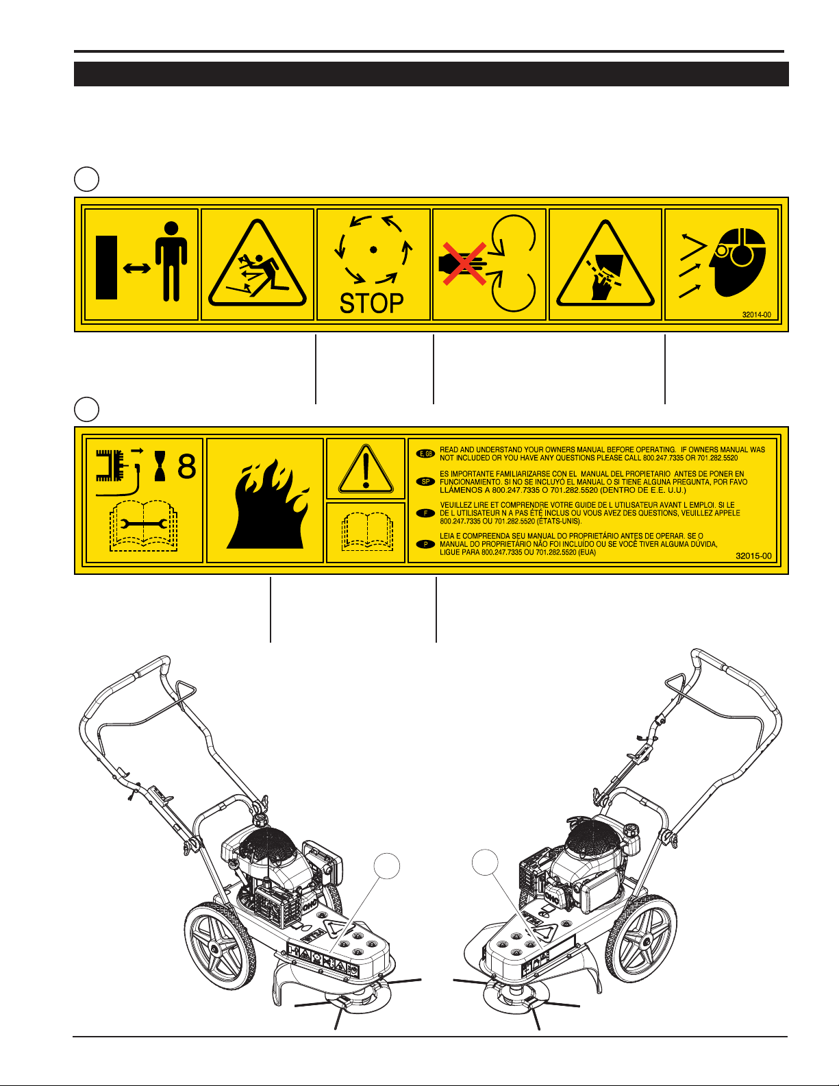
1.6 SAFETY DECAL LOCATIONS
Familiarize yourself with all of the safety and operational decals on the machine and the associated hazards. See the
engine owner’s manual or contact the engine manufacturer for engine safety instructions and decals. Make certain that
all safety and operating decals on this machine are kept clean and in good condition. Decals that need replacement
must be applied to their original locations.
1
P/N 32014-00
ENGLISH
DO NOT OPERATE THIS EQUIPMENT IN THE VICINITY
OF BYSTANDERS. DO NOT ALLOW CHILDREN
TO OPERATE THIS EQUIPMENT. ALWAYS STAND
CLEAR OF DISCHARGE AREA WHEN OPERATING
THIS MACHINE.
2
P/N 32015-00
BEFORE INSPECTING OR SERVICING
ANY PART OF THIS MACHINE, SHUT OFF
POWER SOURCE, DISCONNECT SPARK
PLUG WIRE FROM SPARK PLUG AND MAKE
SURE ALL MOVING PARTS HAVE COME TO
A COMPLETE STOP.
KEEP MACHINE CLEAR OF DEBRIS
AND OTHER ACCUMULATIONS.
BUILD UP OF DEBRIS ON MACHINE
CAN CAUSE A FIRE.
MAKE SURE ALL MOVING
PARTS HAVE COME TO
A COMPLETE STOP.
BEFORE INSPECTING
OR SERVICING ANY PART
OF THIS MACHINE,
DO NOT ALLOW HANDS OR ANY PART OF BODY
OR CLOTHING NEAR ANY MOVING PART TO
AVOID SERIOUS PERSONAL INJURY.
READ AND UNDERSTAND YOU OWNERS MANUAL BEFORE OPERATING. IF
OWNERS MANUAL WAS NOT INCLUDED OR YOU HAVE ANY QUESTIONS,
PLEASE CALL 800.247.7335 OR 701.282.5520 (U.S.A.)
OBTAIN AND WEAR
SAFETY GLASSES
AND USE HEARING
PROTECTION AT ALL
TIMES WHEN OPERATING
THIS MACHINE.
1
2
WHEELED TRIMMER
3
Page 8
2
ASSEMBLY
Section
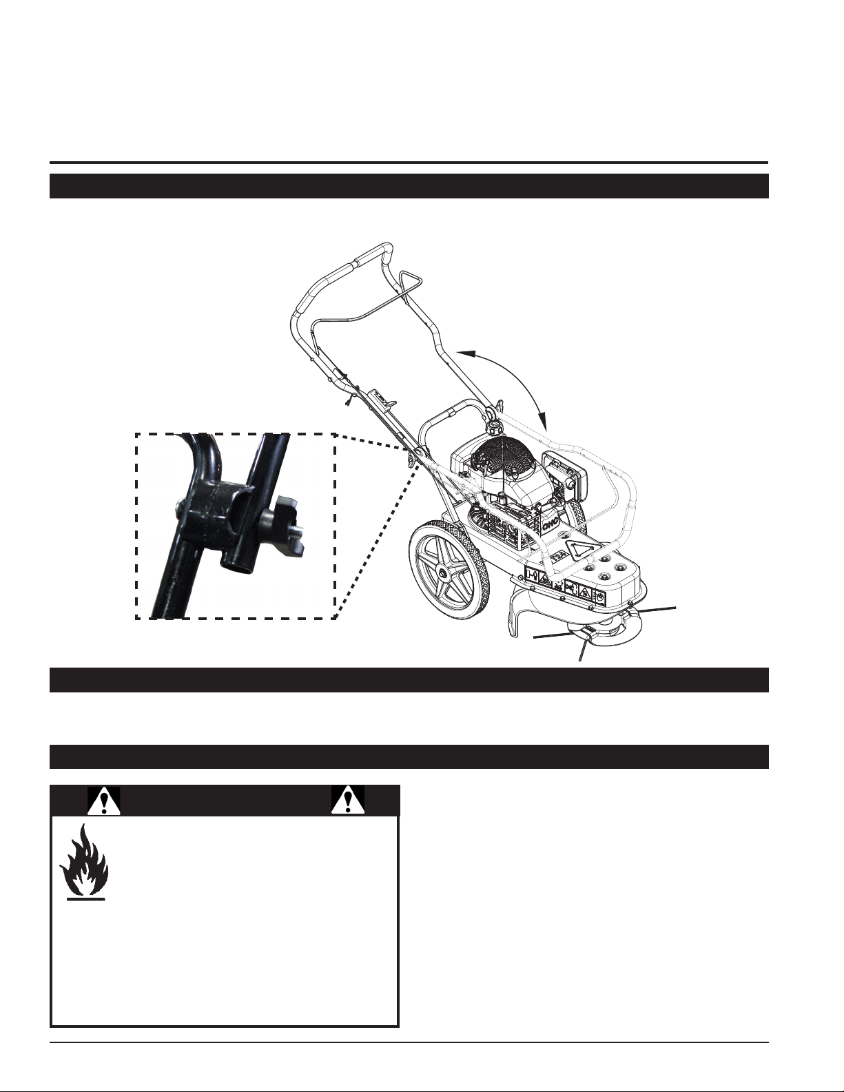
2.1 ADJUST THE HANDLEBAR
To adjust the handlebar into position for use, loosen the locking tee knobs on the notched handlebar retainers. Place
handlebar into operating position and re-tighten knobs.
2.2 ADD OIL
Check the oil level and, if needed, ll the engine crankcase with the type and amount of oil specied in the engine
owner’s manual.
2.3 FILL THE FUEL TANK
WARNING
Gasoline and diesel fuels are highly ammable
and their vapors are explosive. To prevent
personal injury or property damage:
Store fuel only in approved containers, in well
ventilated, unoccupied buildings, away from
sparks or ames. A container with a capacity of 2 gallons
or less with a pouring spout is recommended. Do not ll
the fuel tank while the engine is hot or running, since
spilled fuel could ignite if it comes in contact with hot
parts or sparks from ignition. Do not start the engine
near spilled fuel. Never use fuel as a cleaning agent.
DO NOT MIX OIL WITH FUEL.
4
WHEELED TRIMMER
Use only those types of fuels that are recommended in
your engine owner’s manual.
To add fuel:
1. Stop engine, wait for all parts to stop moving and
disconnect spark plug wire. Remove key from key
switch (if applicable). Allow the engine and muffler to
cool for at least three minutes.
2. Clean area around fuel fill cap and remove cap.
3. Using a clean funnel, fill fuel tank to 1/2” below bottom
of filler neck to provide space for any fuel expansion.
Install fuel fill cap securely and wipe up any spilled
gasoline.
Page 9

3
4
Section
FEATURES & CONTROLS
The following descriptions dene some of the features and
controls of your machine.
REFER TO ENGINE OWNERS MANUAL FOR COMPLETE
ENGINE OPERATING INSTRUCTIONS.
` TRIMMER BAIL
1
When the trimmer bail is engaged, the trimmer disk is
rotating. Release the trimmer bail to stop the Trimmer.
Wait until the trimmer disk has stopped rotating and the
engine is shut off to inspect or service the Trimmer.
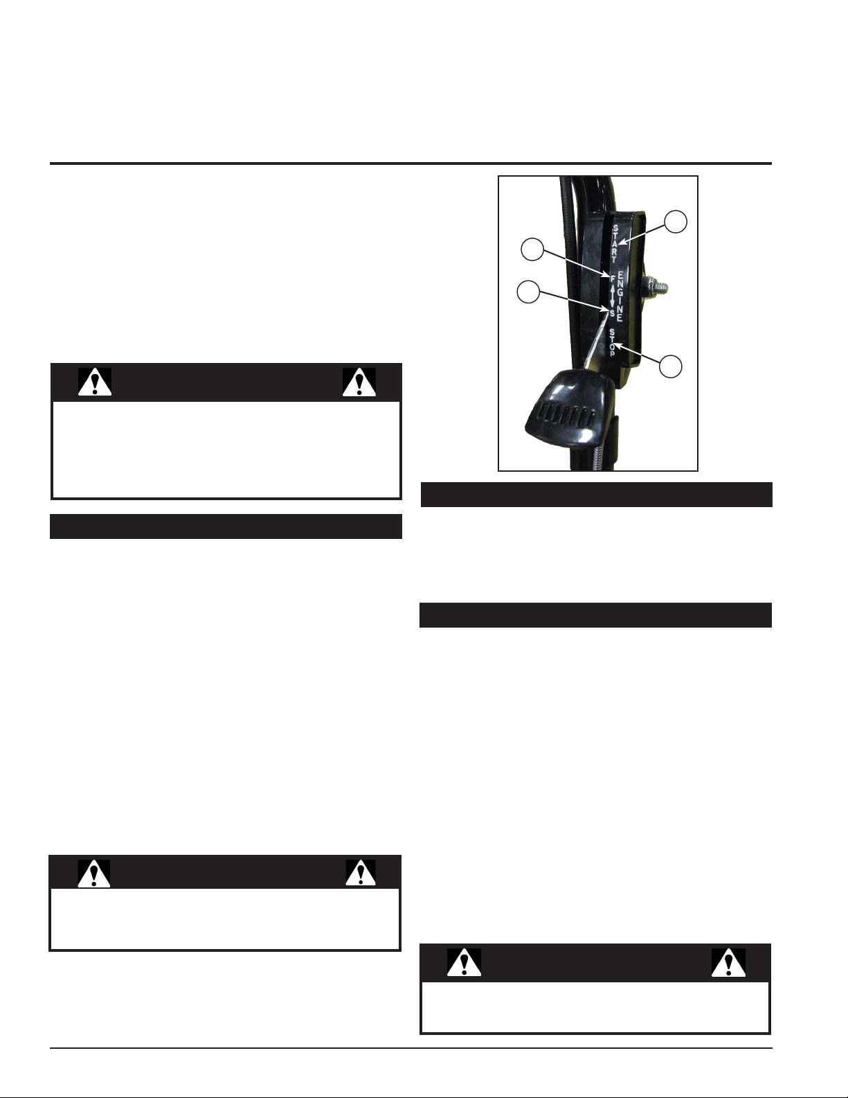
THROTTLE CONTROL LEVER
2
Move throttle to the START position for starting. Operate
engine with the throttle in the (F) FAST position. Move
throttle to the (S) SLOW to idle engine down and then into
the STOP position to shut engine off.
OFF-SET TRIMMING KNOB
3
Loosening the T-shaped knob will allow the cutting head
to pivot left or right up to 10 degrees of angle. (Slightly
lifting the rear wheels off the ground will assist in pivoting
the machine to the desired degree of angle for use). Retighten knob when desired degree of pivot is attained.
(WT24 ONLY)
1
ENGLISH
2
5
4
WT24
3
1
6
WT24T
2
TRIMMER HEAD DISK
4
Patent pending design allows for quick trimmer line
replacement when needed.
MOW BALL
5
Cast iron design provides superior durability and ease of
cutting height change.
TILT CONTROL KNOB (WT24T ONLY)
6
Pull out tilt control knob and tilt machine to the left to
adjust the degree of tilt for the trimmer head and body
when using the Off Center Tilt (OCT) feature. Release
knob when desired angle is reached.
SELF-PROPELLED BAIL (WT24S ONLY)
7
Engages the self propel mode. Pull up the self-propelled
bail located under the handlebar to start the self-propel
mode.
SHIFT LEVER (WT24S ONLY)
8
Used to adjust the trimmer speed. Position 1 is the slowest
and position 3 is the fastest. The ground speed ranges
from 1-3 mph.
5
1
7
8
WT24S
2
5
WHEELED TRIMMER
4
5
Page 10
4
OPERATION
Section
As with any other piece of outdoor power equipment,
getting the feel for how your machine operates and
getting to know the best techniques for particular jobs are
important to overall good performance.
TRIMMING OPERATION
1
2
The trimming operation takes place under the body of the
trimmer, where trimmer string is mounted to a rotating
disk. Material is trimmed and propelled out the edges of
the trimmer.
WARNING
Before operating your machine, be sure you read
and understand all safety, controls and operating
instructions in this owner's manual and on your
machine. Failure to follow these instructions can result
in serious injury or property damage.
4.1 STARTING THE TRIMMER
Move the machine to a clear, level area outdoors before
starting. Do not operate in the vicinity of bystanders. Make
sure the engine is clean and debris has not accumulated
around the mufer.
1. Check fuel and engine oil levels before starting (see
Engine Owners manual for complete engine operation
instructions).
2. Open the fuel shut-off valve.
3. Place the throttle in the START (1) position.
3
4
4.2 STOPPING THE TRIMMER
1. Release the trimmer bail handle, move the throttle to
(S) SLOW (3) position allowing the engine to idle down
and then to the STOP (4) position to kill the engine.
2. Close the fuel shut off valve.
4.3 TRIMMING GUIDE
The intended use of the Wheeled Trimmer is trimming,
mowing and edging. The following guidelines can help you
get started.
1. Run unit at full operating speed before starting to trim,
mow or edge.
4. Grasp the recoil starter cord handle and slowly pull until
resistance is felt, then pull quickly to start the engine
and prevent kickback. Repeat if necessary.
5. Allow engine to warm up. Operate engine in (F) FAST
(2) position.
WARNING
To prevent personal injury, shut off engine and make
sure that the trimmer disk has come to a complete stop
before servicing, adjusting or repairing.
6
WHEELED TRIMMER
2. To begin trimming, start the engine, pull trimmer bail
back. place the trimmer head on the ground and begin
walking slowly.
3. The wheels should remain on the ground at all times to
prevent undue pressure on the trimmer head.
4. The cutting radius is dependant on the amount of cutting
string used and type of application.
5. For difficult conditions and edging, using less than the
full cutting radius is recommended.
WARNING
Inspect and clean engine before each use. Debris
accumulation around the mufer can cause a re.
Page 11

OPERATION
4.4 WT24 — OFF-SET TRIMMING
The Wheeled Trimmer can be adjusted to mow at an
angle. The trimmer body pivots to the left or right up to 10
degrees. To adjust the off-set trimming setting:
1. Loosen the T-shaped knob located on the base of the
machine at the rear.
2. Pivot the machine in the desired direction and desired
angle for use.
3. Re-tighten the knob.
Off-set trimming adjustment knob location
4.6 WT24S — SELF-PROPELLED OPERATION
The WT24S can be used in either push or self-propelled
mode.
TO OPERATE THE SELF-PROPELLED FEATURE:
1. Pull the bail spring handle back.
2. Push forward on the Drive Control lever (on left of
handlebar) until it "clicks" into place.
3. Adjust the speed with the gear shift lever. Position 1
is the slowest and 3 the quickest. The ground speed
ranges from 1-3 mph depending on terrain and material
trimming conditions.
TO OPERATE THE SELF-PROPELLED TRIMMER
CONTROL:
1. With the bail spring pulled back, push forward on the
Trim Control lever (on right of handlebar) until it "clicks"
into place.
2. To stop the self-propelled or trimmer control features,
release the bail spring handle and it will automatically
push back on both control handles, disengaging them
automatically.
ENGLISH
4.5 WT24T — TILT & TRIM FEATURE
The Tilt & Trim feature is used to trim in hard to reach
places. This feature enables both the trimmer head and
body to tilt for trimming close to the ground.
To engage the Tilt & Trim feature, pull adjustment knob
and lift on the handlebar to set the machine in one of the
three additional settings that are available. Release knob
when desired angle is set. Levels available are:
5 degrees
WHEELED TRIMMER
14 degrees10 degrees
7
Page 12

5
SERVICE & MAINTENANCE
Section
5.1 MAINTENANCE SCHEDULE
The items listed in this service and maintenance schedule are
to be checked, and if necessary, corrective action taken. This
schedule is designed for units operating under normal conditions.
If the unit is operating in adverse or severe conditions, it may
be necessary for the items to be checked and serviced more
frequently.
SEE ENGINE OWNER’S MANUAL FOR FURTHER ENGINE
MAINTENANCE AND TROUBLESHOOTING INFORMATION.
COMPONENT
MAINTENANCE
REQUIRED
WARNING
To prevent personal injury, shut off engine and make
sure that the trimmer disk has come to a complete stop
before servicing, adjusting or repairing.
FREQUENCY
REFER TO
ENGINE
OPERATOR’S
MANUAL
BEFORE
EACH USE
EVERY 8
HOURS
EVERY
YEAR
AIR CLEANER CHECK AND CLEAN (1)
ENGINE OIL CHANGE (1) (3)
SPARK PLUG CHECK CONDITION AND GAP
ENGINE OIL CHECK/FILL (1) (3)
FUEL TANK CHECK/FILL
ALL INTERNAL AND EXTERNAL
NUTS AND BOLTS
ENTIRE MACHINE CLEAN
COOLING SHROUDS CLEAN (1) (2)
STARTER DRIVE SERVICE (2)
(1) Perform more frequently in dusty, dirty or severe usage conditions.
(2) Have a Subaru engine service dealer perform this service.
(3) Change oil after rst 5 to 8 hrs of use, then every 50 hours or every season.
As the Limited Warranty states, failure by the Owner to perform normal maintenance will void the machine’s warranty.
CHECK TIGHTNESS
5.2 ENGINE MAINTENANCE
Maintenance is essential in preserving engine life. Clean
the engine periodically to remove grass and buildup. The
engine owners manual addresses cleaning the air lter
and changing the oil. Service engine according to the
maintenance schedule in your engine owners manual.
Remember to inspect and clean engine cooling ns as
needed.
8
WHEELED TRIMMER
WARNING
Clean grass and buildup from the engine periodically.
Dusty conditions will require frequent cleaning.
Page 13
SERVICE & MAINTENANCE
WARNING
BEFORE INSPECTING OR SERVICING ANY PART OF THIS MACHINE, SHUT OFF POWER SOURCE,
DISCONNECT SPARK PLUG WIRE FROM SPARK PLUG AND MAKE SURE ALL MOVING PARTS HAVE COME TO A COMPLETE STOP.
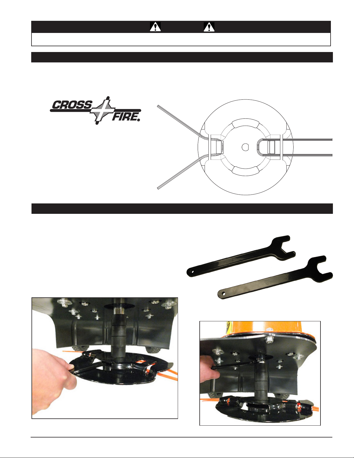
5.3 CUTTING STRING REPLACEMENT
Wheeled trimmers come standard with ECHO Cross Fire® cutting string in .175" diameter. Replacement cutting string is
available in .175" or .155" diameters in ECHO Cross Fire® or .155" in the round design. See Section 8 - Options, for a
complete list of replacement cutting string options. WARNING: Cut replacement string pieces to no longer than 20" (50
cm). Pieces longer than 20" (50 cm) can and will damage the trimmer shield.
To replace the cutting string:
1. Fold a 20" piece of cutting string in half.
Insert the piece into slot of trimmer head
disk until the bend in the string is past the
line holder tab.
2. Pull the string underneath the tab until
secured in place. It may be necessary to
remove pieces of broken or worn string before
new string can be properly installed.
ENGLISH
5.4 CUTTING HEIGHT ADJUSTMENT
The standard cutting height is 2-3/4". The cutting height
can be adjusted up in 1" increments. To adjust the cutting
height:
1. Insert a 1-1/16" open end wrench or wrench from
77524-00 wrench kit through opening on the trimmer
disk head and onto mow ball.
2. NOTE: It is important to orientate the wrench with
narrow side to the right as shown in Figure 5.1. This
will prevent having to back the wrench off to remove it
from the disk head slot.
3. Place 1" open end wrench or wrench from 77524-00
wrench kit on spindle.
Note: A wrench kit is available for removing mow ball,
please order kit #77524-00 from your local dealer.
Figure 5.1, 1-1/16" open-end wrench for Trimmer ball
WHEELED TRIMMER
Figure 5.2, 1" open-end wrench on spindle spacer
9
Page 14

SERVICE & MAINTENANCE
WARNING
DISCONNECT SPARK PLUG WIRE FROM SPARK PLUG AND MAKE SURE ALL MOVING PARTS HAVE COME TO A COMPLETE STOP.
4. Turn wrenches in opposite directions to loosen and
remove mow ball, disk head and spacers.
5. Place spacers in proper configuration above or below
the disk head (and above the mow ball) to set desired
height. See Figure 5.4.
BEFORE INSPECTING OR SERVICING ANY PART OF THIS MACHINE, SHUT OFF POWER SOURCE,
TRIMMER BAIL ADJUSTMENT
Periodically, the trimmer engagement cable may need to
Periodically, the trimmer engagement cable may need to
be adjusted to account for belt break-in and wear.
be adjusted to account for belt break-in and wear.
Increase belt tension by loosening the top 1/2” nut. Loosen
Increase belt tension by loosening the top 1/2” nut. Loosen
nut 1-1/2 turns at a time and tighten the lower 1/2” nut.
nut 1-1/2 turns at a time and tighten the lower 1/2” nut.
Keep adjusting until desired belt tension is accomplished
Keep adjusting until desired belt tension is accomplished
without the trimmer disk continuing to turn. If the disk head
without the trimmer disk continuing to turn. If the disk head
turns without the bail engaged, there is too much tension.
turns without the bail engaged, there is too much tension.
Decrease belt tension by loosening the lower 1/2” nut.
Decrease belt tension by loosening the lower 1/2” nut.
Loosen nut 1-1/2 turns at a time and tighten the upper
Loosen nut 1-1/2 turns at a time and tighten the upper
1/2” nut. Proper belt tension is accomplished when the
1/2” nut. Proper belt tension is accomplished when the
trimmer disk turns upon engagement and stops turning
trimmer disk turns upon engagement and stops turning
upon releasing the engagement bail.
upon releasing the engagement bail.
Figure 5.3, Wrench locations for cutting height adjustment
Lowest cutting
height - 1-3/4"
Figure 5.4
Maximum cutting
height - 4-3/4"
5.5 WT24S — TRANSMISSION ADJUSTMENT
The WT24S operates with a 3-speed transmission.
Periodically, the shift cable may need to be adjusted to
allow proper function of all three gears.
To adjust:
1. Locate in-line adjustor on the shift
cable.
2. Loosen the smaller nut (1) to allow
adjustment of the larger adjustment
barrel (2).
3. Tighten or loosen the adjustment
barrel, to lengthen or shorten
as needed, to achieve all three
positions of the transmission.
4. Once proper adjustment is
achieved, re-tighten the smaller
nut to secure.
Figura 5.5
1
2
Increasing belt tension setting
Standard belt tension setting
10
WHEELED TRIMMER
Page 15

SERVICE & MAINTENANCE
WARNING
DISCONNECT SPARK PLUG WIRE FROM SPARK PLUG AND MAKE SURE ALL MOVING PARTS HAVE COME TO A COMPLETE STOP.
BEFORE INSPECTING OR SERVICING ANY PART OF THIS MACHINE, SHUT OFF POWER SOURCE,
5.6 WT24 AND WT24T CUTTING HEAD
DRIVE BELT REPLACEMENT
Decreasing belt tension setting
WARNING
ENGLISH
To prevent uid spills, it is recommended that the
engine oil and gasoline be removed before beginning
the belt removal/service procedures.
To replace drive belt on WT24 and WT24T:
1. Tip machine back onto handle bar and support main
body 4-1/2" off of the ground. See Figure 5.6.
2. Remove mow ball (1), disk head (2), spacers (3), and
spindle spacer (4). See Section 5.3 cutting head ad-
justment for mow ball removal.
Note: To release spindle spacer, gently tap
on spacer to remove
from spindle shaft.
Figure 5.6
3. Remove the six bolts (5), washers and nuts at the
front of the trimmer and three bolts (6) from each
side of the trimmer.
WHEELED TRIMMER
Figure 5.7
11
Page 16

SERVICE & MAINTENANCE
WARNING
DISCONNECT SPARK PLUG WIRE FROM SPARK PLUG AND MAKE SURE ALL MOVING PARTS HAVE COME TO A COMPLETE STOP.
BEFORE INSPECTING OR SERVICING ANY PART OF THIS MACHINE, SHUT OFF POWER SOURCE,
4. Separate body (7) from trimmer base (8).
5. Remove pulley (9) from engine by rst removing the
3/8 x 1" bolt (10) and slide pulley off of engine shaft.
5
7
6
9
10
12
11
6. Slide trimmer head pulley (11) out from between the
belt guides to replace belt (12) on pulley and slide
pulley back between belt guides.
Figure 5.9
2
1
Figure 5.8
8
4
3
7. Reinstall drive pulley (9) by rst putting belt (12) on
to pulley before sliding pulley onto engine shaft between the two belts guides. See Figure 10. Torque
bolt to 29 ft-lbs. Also ensure belt is between idler
and belt guide on idler bracket. See Figure 5.11.
Note: Ensure the gap between drive pulley and belt guide
is 1/8".
12
Figure 5.10
WHEELED TRIMMER
Page 17

SERVICE & MAINTENANCE
WARNING
BEFORE INSPECTING OR SERVICING ANY PART OF THIS MACHINE, SHUT OFF POWER SOURCE,
DISCONNECT SPARK PLUG WIRE FROM SPARK PLUG AND MAKE SURE ALL MOVING PARTS HAVE COME TO A COMPLETE STOP.
9. Reinstall mow ball (1), disk head (2), spacers (3),
and spindle spacer (4). Ensure spindle spacer is oriented as shown in Figure 5.13.
ENGLISH
Figure 5.11
8. With belt installed onto trimmer, mount trimmer base
plate (8) onto trimmer body (7) and fasten with the
six bolts (5), washers and nuts at the front of the
trimmer and torque to 13 ft-lbs. Then fasten the six
bolts (6) on the side of the trimmer and torque to 15
ft-lbs.
Figure 5.13
5.7 WT24S CUTTING HEAD DRIVE BELT
REPLACEMENT
WARNING
To prevent uid spills, it is recommended that the
engine oil and gasoline be removed before beginning
the belt removal/service procedures.
To replace cutting head drive belt on WT24S:
1. Remove the two 5/16 x 1" screws (5) securing the
undercarriage cover (6) and set cover aside.
Figure 5.12
WHEELED TRIMMER
Figure 5.14, Remove undercarriage cover
13
Page 18

SERVICE & MAINTENANCE
WARNING
DISCONNECT SPARK PLUG WIRE FROM SPARK PLUG AND MAKE SURE ALL MOVING PARTS HAVE COME TO A COMPLETE STOP.
BEFORE INSPECTING OR SERVICING ANY PART OF THIS MACHINE, SHUT OFF POWER SOURCE,
2. Position the handlebars so the machine can be laid
back and supported on blocks as shown in Figure
5.15
Figure 5.15
3. Remove mow ball (1), disk head (2), spacers (3), and
spindle spacer (4). See Section 5.3 cutting head ad-
justment for mow ball removal.
Note: To release spindle spacer, gently tap on spacer to
remove from spindle shaft.
11
9
4. Remove the six 5/16 x 3/4" bolts (9), washers and
nuts around the front of the trimmer and two 5/16 x
1" bolts (11) from each side of the trimmer as shown
in Figures 5.17 & 5.18.
Figure 5.17
15
12
13
14
6
10
5
7
4
8
3
Figure 5.18
2
1
14
Figure 5.16
WHEELED TRIMMER
Page 19

SERVICE & MAINTENANCE
WARNING
DISCONNECT SPARK PLUG WIRE FROM SPARK PLUG AND MAKE SURE ALL MOVING PARTS HAVE COME TO A COMPLETE STOP.
BEFORE INSPECTING OR SERVICING ANY PART OF THIS MACHINE, SHUT OFF POWER SOURCE,
Figure 5.21
5.8 WT24S — DRIVE CHAIN ADJUSTMENT
The WT24S operates with a drive chain. Periodically, this
chain may need to be adjusted. To adjust:
1. Remove plastic shield.
2. Loosen the four 1/4” nuts located nearest to trimmer
axle on both sides. See illustration below.
3. Slide the axle forward to remove the slack in the chain.
Figure 5.19
5. To remove the belt, it will be necessary to loosen
the 3/8 x 1" bolt securing the 4" pulley to the engine
crankshaft. It should not be necessary to completely
remove the bolt.
4. Once the slack is removed and the axle is square to
the rear of the trimmer, re-tighten the four 1/4" nuts.
ENGLISH
Figure 5.20
6. Replace belt, (part #31995-00) and reverse the previous steps to reassemble machine.
WHEELED TRIMMER
Figure 5.22
15
Page 20

SERVICE & MAINTENANCE
WARNING
DISCONNECT SPARK PLUG WIRE FROM SPARK PLUG AND MAKE SURE ALL MOVING PARTS HAVE COME TO A COMPLETE STOP.
BEFORE INSPECTING OR SERVICING ANY PART OF THIS MACHINE, SHUT OFF POWER SOURCE,
5.9 WT24S TRANSMISSION BELT REPLACEMENT
To replace transmission belt on WT24S:
1. Complete steps 1-5 from the previous Section 5.7.
However, it will be neccesary to completely remove
the 4" pulley to access the inner transmission belt.
2
3
4
4
Figure 5.23
2. Next, remove the four 5/16 x 5/8" screws (2) securing
the transmission assembly (1) to the trimmer body.
Figure 5.24, Transmission assembly removal
1
Figure 5.25
3. Slide transmission assembly out of the mounting location.
4. Replace belt, (part #32124-00) and reverse the previous steps to reassemble machine.
Figure 5.26
16
WHEELED TRIMMER
Page 21

6
Section
TROUBLESHOOTING
Before performing any of the corrections in this troubleshooting chart, refer to the appropriate information contained in
this manual for the correct safety precautions and operating or maintenance procedures. Contact your dealer or the
factory for service problems with the machine.
PROBLEM POSSIBLE CAUSE REMEDY
1. Replace belt
2. Replace pulleys
3. Repair bearings
4. Cable unattached to idler bracket
1. Replace cutting string
2. Reduce the trimming area by half or raise
the trimmer head off the ground
3. Speed up engine to full throttle
1. Reduce cutting string length
2. Replace drive belt
3. Reduce the trimming area by half or raise the
trimmer head slightly off the ground
4. Adjust trimmer engagement cable
Trimmer disk does not
turn.
Cutting is slow or rough.
Trimmer requires exces-
sive
power or stalls.
1. Broken or damaged belt
2. Failed pulleys
3. Failed bearings
1. Cutting string is too weak
2. Growth is too thick or heavy
3. Engine not running at full RPM
1. Cutting string is too long
2. Drive belt is loose or worn
3. Growth is too thick or heavy
4. Trimmer engagement cable out of
adjustment
ENGLISH
Drive belt squealing or
smoking.
Engine won't start or
is hard to start.
Drive belt rolling or falling
off pulleys.
Excessive vibration felt in
the handle bar
1. Drive belt is loose or worn
2. Worn or damaged pulley
1. Refer to engine owner's manual
2. Spark plug wire is disconnected
3. Spark plug is defective
4. Gas line is obstructed
5. Dirty, stale, water-contaminated
gas
1. Belt not tensioned properly
2. Spindle bearings failed
1. Bent spindle shaft
2. Damaged trimmer head
3. Trimmer head with dried on plant
matter
1. Adjust or replace drive belt
2. Replace pulley
1. Connect loose wire to the spark plug
2. Replace spark plug
3. Remove gas line at carburetor and check
for obstruction. Drain gas tank and refill with
fresh gasoline
4. Drain tank and fill with fresh gasoline
1. Adjust trimmer engagement cable
2. Replace bearings
1. Replace spindle shaft
2. Replace trimmer head
3. Remove trimmer head. Soak in water
overnight. Wash and rinse off plant matter.
Reinstall.
WHEELED TRIMMER
17
Page 22

7
SPECIFICATIONS
Section
WT24 WT24T WT24S
ENGINE EA190V Subaru
DRIVE Push Self-Propelled
CUTTING WIDTH 24"
WHEEL SUPPORT Ball Bearings
CUTTING HEIGHT 1-3/4" minimum, 4 3/4" maximum (Adjustable in 1" increments)
NYLON CUTTING STRING
CUTTING STRING ROUND .155" Optional
WEIGHT 92 lbs. 95 lbs 95 lbs
DIMENSIONS 33 L X 21-3/8 W X 23-1/4 H
START Recoil
FUEL CAPACITY .24 gal. (.90 L)
.175" Standard
.155" Optional
18
WHEELED TRIMMER
Page 23

SPECIFICATIONS
BOLT TORQUE
The tables below are for reference purposes only and their use by anyone is entirely voluntary, unless otherwise noted.
Reliance on their content for any purpose is at the sole risk of that person and any loss or damage resulting from the
use of this information is the responsibility of that person.
SAE
SAE - 2
SAE - 5
SAE - 8
BOLT DIAMETER
Grade
and
Head
A
Markings
ENGLISH
BOLT DIAMETER (A)
1/4” 7.5 5.5 11 8 16 12
5/16” 15 11 23 17 34 25
3/8” 27 20 41 30 61 45
7/16” 41 30 68 50 95 70
1/2” 68 50 102 75 149 110
9/16” 97 70 149 110 203 150
5/8” 122 90 203 150 312 230
3/4” 217 160 353 260 515 380
7/8” 230 170 542 400 814 600
1” 298 220 786 580 1220 900
1-1/8” 407 300 1085 800 1736 1280
1-1/4” 570 420 2631 1940 2468 1820
SAE 2 SAE 5 SAE 8
N.m Ft-lb. N.m Ft-lb. N.m Ft-lb.
BOLT TORQUE *
ENGLISH
METRIC
Grade
and
Head
Markings
4.8
4.8
8.8
8.8 10.9
10.9
12.9
12.9
BOLT DIAMETER
A
METRIC
BOLT DIAMETER
(A)
M3 0.5 0.4 - - - - - -
M4 3 2.2 - - - - - -
M5 5 4 - - - - - -
M6 6 4.5 11 8.5 17 12 19 14.5
M8 15 11 28 20 40 30 47 35
M10 29 21 55 40 80 60 95 70
M12 50 37 95 70 140 105 165 120
M14 80 60 150 110 225 165 260 190
M16 125 92 240 175 350 255 400 300
M18 175 125 330 250 475 350 560 410
M20 240 180 475 350 675 500 800 580
M22 330 250 650 475 925 675 1075 800
M24 425 310 825 600 1150 850 1350 1000
M27 625 450 1200 875 1700 1250 2000 1500
4.8 8.8 10.9 12.9
N.m Ft-lb. N.m Ft-lb. N.m Ft-lb. N.m Ft-lb.
* Torque value for bolts and capscrews are identified by their head markings.
Torque figures indicated above are valid for non-greased or non-oiled threads and heads unless otherwise specified. Therefore, do not
grease or oil bolts or capscrews unless otherwise specified in this manual. When using locking elements, increase torque values by 5%.
BOLT TORQUE *
WHEELED TRIMMER
19
Page 24

8
Section
OPTIONS
PART NUMBER DESCRIPTION
32029-00 .155 DIA. CROSS-FIRE®, 10 PACK (20” PRE-CUT LENGTH):
32030-00 .155 DIA. ROUND, 10 PACK (20” PRE-CUT LENGTH):
32031-00 .175 DIA. CROSS-FIRE®, 10 PACK (20” PRE-CUT LENGTH):
32033-00 .175 DIA. CROSS-FIRE®, 1 LB DONUT
32035-00 .175 DIA. CROSS-FIRE®, 3 LB SPOOL
32086-00
74548-00 SABRE TOOTH BLADE (NOT APPROVED FOR CE CONFORMITY)
77445-00 LINE HOLDER
77524-00 KIT, TRIMMER WRENCH SET
Saber, Tooth Blade, 74548-00 (Not approved for CE conformity)
TRIPLE BLADE BRUSH CUTTER (NOT APPROVED FOR CE CONFORMITY)
Triple Blade Brush Cutter, 32086-00 (Not approved for CE conformity)
20
Trimmer Wrench Set, 77524-00
Line Holder, 77445-00
WHEELED TRIMMER
Page 25

ECHO BEAR CAT
www.bearcatproducts.com
237 NW 12th Street, West Fargo, ND 58078-0849
Phone: 701.282.5520 • Toll Free: 888.645.4520 • Fax: 701.282.9522
E-mail: service@bearcatproducts.com • sales@bearcatproducts.com
 Loading...