

Page 1
www.echorobotics.com
DRAFT 05-23-2019
Technical Manual
Robotic Mower
TM-2000
P/N 99922205383
VERSION 1.0
05/28/2019
©2019 ECHO Incorporated. All Rights Reserved.
EN ENGLISH
Page 2

Contents
DRAFT 05-23-2019
Chapter: 1 Important Information . . . . . . . . . . . . . . . . . . . . . . . . . . . 1
Administrative Support . . . . . . . . . . . . . . . . . . . . . . . . . . . . 1
FCC Declarations . . . . . . . . . . . . . . . . . . . . . . . . . . . . . . . 1
California Proposition 65 . . . . . . . . . . . . . . . . . . . . . . . . . . . 1
Chapter: 2 Safety Information . . . . . . . . . . . . . . . . . . . . . . . . . . . . . . 1
Safety Symbols . . . . . . . . . . . . . . . . . . . . . . . . . . . . . . . . 2
Chapter: 3 Theory of Operation . . . . . . . . . . . . . . . . . . . . . . . . . . . . . 2
Chapter: 4 System Components . . . . . . . . . . . . . . . . . . . . . . . . . . . . . 3
Robot Components . . . . . . . . . . . . . . . . . . . . . . . . . . . . . . 3
The Charging Station . . . . . . . . . . . . . . . . . . . . . . . . . . . . . 6
Chapter: 5 How the Robot Works . . . . . . . . . . . . . . . . . . . . . . . . . . . . 6
Autonomous Mission State . . . . . . . . . . . . . . . . . . . . . . . . . 6
Inactive Modes . . . . . . . . . . . . . . . . . . . . . . . . . . . . . . . 10
Chapter: 6 Installation . . . . . . . . . . . . . . . . . . . . . . . . . . . . . . . . . 10
Station Loop Wire Installation . . . . . . . . . . . . . . . . . . . . . . . 11
Peripheral Wire Installation . . . . . . . . . . . . . . . . . . . . . . . . 11
Peripheral Wire Installation Offsets . . . . . . . . . . . . . . . . . . . . 12
Sites Containing Narrow Straits . . . . . . . . . . . . . . . . . . . . . . 13
Sites With Long Lanes . . . . . . . . . . . . . . . . . . . . . . . . . . . 13
Obstacles . . . . . . . . . . . . . . . . . . . . . . . . . . . . . . . . . . 13
Islands . . . . . . . . . . . . . . . . . . . . . . . . . . . . . . . . . . . . 14
Water Obstacle . . . . . . . . . . . . . . . . . . . . . . . . . . . . . . . 15
Sloped Fields . . . . . . . . . . . . . . . . . . . . . . . . . . . . . . . . 15
Configuration . . . . . . . . . . . . . . . . . . . . . . . . . . . . . . . . 16
Overlaps . . . . . . . . . . . . . . . . . . . . . . . . . . . . . . . . . . . 17
Multi-Field Peripheral Wire Installation . . . . . . . . . . . . . . . . . . 18
Configuration . . . . . . . . . . . . . . . . . . . . . . . . . . . . . . . . 18
Configuration Examples . . . . . . . . . . . . . . . . . . . . . . . . . . 20
Chapter: 7 Using the Robot . . . . . . . . . . . . . . . . . . . . . . . . . . . . . . 26
Safety Measures . . . . . . . . . . . . . . . . . . . . . . . . . . . . . . 26
The LCD Screen . . . . . . . . . . . . . . . . . . . . . . . . . . . . . . . 26
The Actions Menu . . . . . . . . . . . . . . . . . . . . . . . . . . . . . . 26
The Settings Menu . . . . . . . . . . . . . . . . . . . . . . . . . . . . . 27
i
Page 3

Service Menu . . . . . . . . . . . . . . . . . . . . . . . . . . . . . . . . 30
DRAFT 05-23-2019
Advanced Parameters . . . . . . . . . . . . . . . . . . . . . . . . . . . 34
Technician's Menu . . . . . . . . . . . . . . . . . . . . . . . . . . . . . 34
Error Messages . . . . . . . . . . . . . . . . . . . . . . . . . . . . . . . 42
Connecting to Robots . . . . . . . . . . . . . . . . . . . . . . . . . . . . 45
Chapter: 8 Maintenance Procedures . . . . . . . . . . . . . . . . . . . . . . . . . 55
General Inspection and Cleaning . . . . . . . . . . . . . . . . . . . . . 55
Cover and Electrical Cables . . . . . . . . . . . . . . . . . . . . . . . . . 55
Charge Contacts . . . . . . . . . . . . . . . . . . . . . . . . . . . . . . . 56
Sonar Sensors and Bumper . . . . . . . . . . . . . . . . . . . . . . . . 56
Coil . . . . . . . . . . . . . . . . . . . . . . . . . . . . . . . . . . . . . . 56
Chassis . . . . . . . . . . . . . . . . . . . . . . . . . . . . . . . . . . . . 56
Front and Rear Lift Sensors . . . . . . . . . . . . . . . . . . . . . . . . 57
Front Wheel Assemblies . . . . . . . . . . . . . . . . . . . . . . . . . . 57
Rear Wheels and Rear Wheel Brushes . . . . . . . . . . . . . . . . . . 57
Cutting Height System . . . . . . . . . . . . . . . . . . . . . . . . . . . 58
Cutting Heads . . . . . . . . . . . . . . . . . . . . . . . . . . . . . . . . 58
Winter Storage . . . . . . . . . . . . . . . . . . . . . . . . . . . . . . . 58
Chapter: 9 Service Procedures . . . . . . . . . . . . . . . . . . . . . . . . . . . . 58
Sonar Replacement . . . . . . . . . . . . . . . . . . . . . . . . . . . . . 59
Bumper Replacement . . . . . . . . . . . . . . . . . . . . . . . . . . . 59
Front Lift Cushion Replacement . . . . . . . . . . . . . . . . . . . . . . 59
Rear Lift Cushion Replacement . . . . . . . . . . . . . . . . . . . . . . 60
Front Wheel Replacement . . . . . . . . . . . . . . . . . . . . . . . . . 60
Rear Wheel Replacement . . . . . . . . . . . . . . . . . . . . . . . . . 60
Gear Motor Replacement . . . . . . . . . . . . . . . . . . . . . . . . . 61
Battery Removal and Installation . . . . . . . . . . . . . . . . . . . . . 62
Cutting Disk Service . . . . . . . . . . . . . . . . . . . . . . . . . . . . . 63
Blade Replacement . . . . . . . . . . . . . . . . . . . . . . . . . . . . . 63
Aluminum Anti-friction Disc Replacement . . . . . . . . . . . . . . . . 64
Cutting Head Reassembly . . . . . . . . . . . . . . . . . . . . . . . . . 64
Cutting Motor Service . . . . . . . . . . . . . . . . . . . . . . . . . . . 65
Cutting Motor Cable Replacement . . . . . . . . . . . . . . . . . . . . 65
Correcting Stop Button Lid Closure Problems . . . . . . . . . . . . . . 65
Chapter: 10 Robot Accessories . . . . . . . . . . . . . . . . . . . . . . . . . . . . . 67
Wheel Brush Kit . . . . . . . . . . . . . . . . . . . . . . . . . . . . . . . 67
Groomer Kit . . . . . . . . . . . . . . . . . . . . . . . . . . . . . . . . . 67
Chapter: 11 Battery Service and Installation . . . . . . . . . . . . . . . . . . . . . 67
Safety Information . . . . . . . . . . . . . . . . . . . . . . . . . . . . . 68
Operation . . . . . . . . . . . . . . . . . . . . . . . . . . . . . . . . . . 68
ii
Page 4

Battery Removal and Installation . . . . . . . . . . . . . . . . . . . . . 68
DRAFT 05-23-2019
Removal and Installation (RP-1200) . . . . . . . . . . . . . . . . . . . . 69
Storage . . . . . . . . . . . . . . . . . . . . . . . . . . . . . . . . . . . . 69
Recycling . . . . . . . . . . . . . . . . . . . . . . . . . . . . . . . . . . . 70
Chapter: 12 Torque References . . . . . . . . . . . . . . . . . . . . . . . . . . . . . 70
Mower Body . . . . . . . . . . . . . . . . . . . . . . . . . . . . . . . . . 71
Cutting Height . . . . . . . . . . . . . . . . . . . . . . . . . . . . . . . . 72
Electrical Box, Battery, and Housing . . . . . . . . . . . . . . . . . . . . 73
Lift Sensors . . . . . . . . . . . . . . . . . . . . . . . . . . . . . . . . . 74
Wheels, Motor and Gear Box . . . . . . . . . . . . . . . . . . . . . . . 75
Cutting Head . . . . . . . . . . . . . . . . . . . . . . . . . . . . . . . . 76
Electrical Parts . . . . . . . . . . . . . . . . . . . . . . . . . . . . . . . . 77
Main Frame . . . . . . . . . . . . . . . . . . . . . . . . . . . . . . . . . 78
Main Bars . . . . . . . . . . . . . . . . . . . . . . . . . . . . . . . . . . 79
Accessories . . . . . . . . . . . . . . . . . . . . . . . . . . . . . . . . . 80
Cover and Chassis . . . . . . . . . . . . . . . . . . . . . . . . . . . . . . 81
Gear Motor, Cutting Head, and Front Wheel . . . . . . . . . . . . . . . 83
Chapter: 13 Specifications . . . . . . . . . . . . . . . . . . . . . . . . . . . . . . . 84
Capacity . . . . . . . . . . . . . . . . . . . . . . . . . . . . . . . . . . . 84
Cutting . . . . . . . . . . . . . . . . . . . . . . . . . . . . . . . . . . . . 84
Battery . . . . . . . . . . . . . . . . . . . . . . . . . . . . . . . . . . . . 84
Weight and Dimensions . . . . . . . . . . . . . . . . . . . . . . . . . . 84
Software and Monitoring . . . . . . . . . . . . . . . . . . . . . . . . . 84
Intelligence . . . . . . . . . . . . . . . . . . . . . . . . . . . . . . . . . 84
Safety . . . . . . . . . . . . . . . . . . . . . . . . . . . . . . . . . . . . 84
Dimensions . . . . . . . . . . . . . . . . . . . . . . . . . . . . . . . . . 85
iii
Page 5
IMPORTANT INFORMATION
DRAFT 05-23-2019
ADMINISTRATIVE SUPPORT
1 Important Information
©2019 ECHO Incorporated. All Rights Reserved.
This manual, or parts thereof, may not be reproduced
in any form, by any method, for any purpose.
ECHO has taken reasonable care in compiling this docu-
ment, however ECHO accepts no liability whatsoever
for any error or omission in the information contained
herein and gives no other warranty or undertaking as
to its accuracy.
ECHO can accept no responsibility for damages,
resulting from the use of the operating software. In
addition, we refer to the conditions of use specified in
the license contract. ECHO reserves the right to amend
this document at any time without prior notice.
ECHO and its affiliates are not liable for damages or
losses related to such security breaches, any unauthorized access, interference, intrusion, leakage and/or
theft of data or information.
This manual contains the original instructions. Information contained in this manual is provided as an indication and is in no way contractual. It can be changed by
ECHO, without the need for prior announcement.
Obtain updated information at: myrobot.echorobotics.com.
The robot has been designed to high safety standards.
Risk is always possible. Read and understand all Safety
and Information Symbols.
This manual refers to Generation 2.0 series of robots
with software version 3.5
user will be required to correct the interference at their
own expense.
1.3 California Proposition 65
Cancer and Reproductive Harm
www.P65Warnings.ca.gov
2 Safety Information
Throughout this manual and on the product itself, you
will find safety alerts and helpful, informational
messages preceded by symbols or key words. The
following is an explanation of those symbols and key
words and what they mean to you.
Circle and Slash Symbol:
This symbol means the specific action shown is prohibited. Ignoring this symbol can result in damage to property and serious or fatal injury.
The safety alert symbol accompanied by the word
“DANGER” calls attention to an act or condition which
WILL lead to serious personal injury or death if not
avoided.
1.1 Administrative Support
Send emails to: admin@echorobotics.com.
1.2 FCC Declarations
This equipment has been tested and found to comply
with the limits/or a Class A digital device, pursuant to
part 15 of the FCC Rules. These limits are designed to
provide reasonable protection against harmful interference when the equipment is operated in a commercial environment. This equipment generates, uses, and
can radiate radio frequency energy and, if not installed
and used in accordance with the instruction manual,
may cause harmful interference to radio communications. Operation of this equipment in a residential area
is likely to cause harmful interference in which case the
The safety alert symbol accompanied by the word
“WARNING” calls attention to an act or condition which
CAN lead to serious personal injury or death if not
avoided.
The safety alert symbol accompanied by the word
“CAUTION” calls attention to an act or condition which
may lead to minor or moderate personal injury if not
avoided.
The enclosed message provides information necessary
for the protection of the unit.
1
Page 6
THEORY OF OPERATION
DRAFT 05-23-2019
SAFETY SYMBOLS
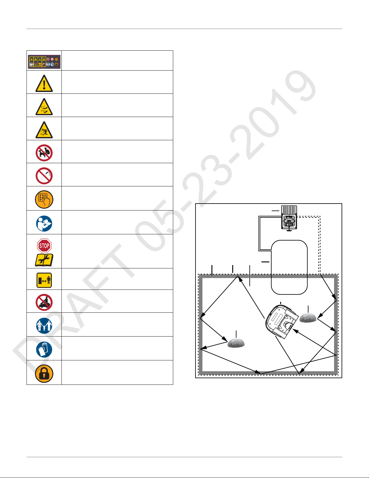
2.1 Safety Symbols
Safety and Information Label
Caution: The robot can be dangerous if
misused.
Never place hands or feet under the
robot while operating.
Beware of projectiles. Keep a safe
distance.
Keep animals away from the robot.
Water cleaning with high pressure jet
systems can cause damage.
The robot is protected by an access
code.
Read the technical manual before using
the robot.
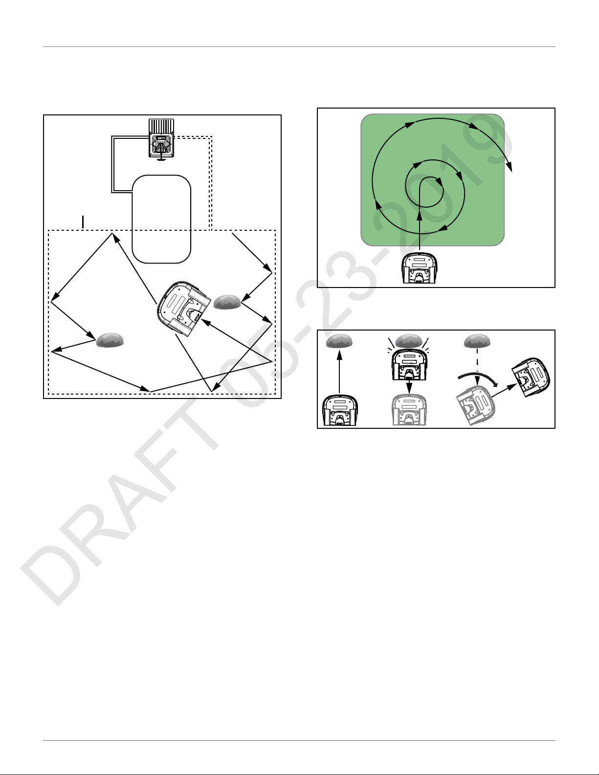
3 Theory of Operation
The robot mows in a random pattern. A peripheral wire
buried in the ground defines the mowing area.
The charging station energizes the peripheral wire. An
electro magnetic field is generated within the mowing
area. The robot senses the magnetic field.
When the robot senses the location of the peripheral
wire, it stops, turns back into the field, and continues
mowing.
The robot is equipped with obstacle detection sensors.
When the robot detects an obstacle it will slow down,
contact the obstacle, then perform a maneuver to
avoid it.
When the battery of the robot needs to be charged, the
robot will stop, move toward the peripheral wire, then
follow a trackborder back to the station loop wire.
When the robot detects the station loop wire, it follows
it to the charging station. The station loop wire guides
the robot into and out of the charging station.
4
Always stop the robot and wait for the
cutting blades to stop before handling
the robot.
Always keep a safe distance from the
robot while handling.
Do not ride the robot.
Keep bystanders away from the robot.
Protective gloves must be worn when
handling the robot, especially the
cutting system.
The robot is equipped with an
anti-theft system.
7 3 2
5
1 – Robot
2 – Mowing area
3 – Peripheral wire
4 – Charging station
5 – Obstacle
6 – Station loop wire
7 – Trackborder
6
1
5
2
Page 7
SYSTEM COMPONENTS
DRAFT 05-23-2019
ROBOT COMPONENTS
4 System Components
3
1
4
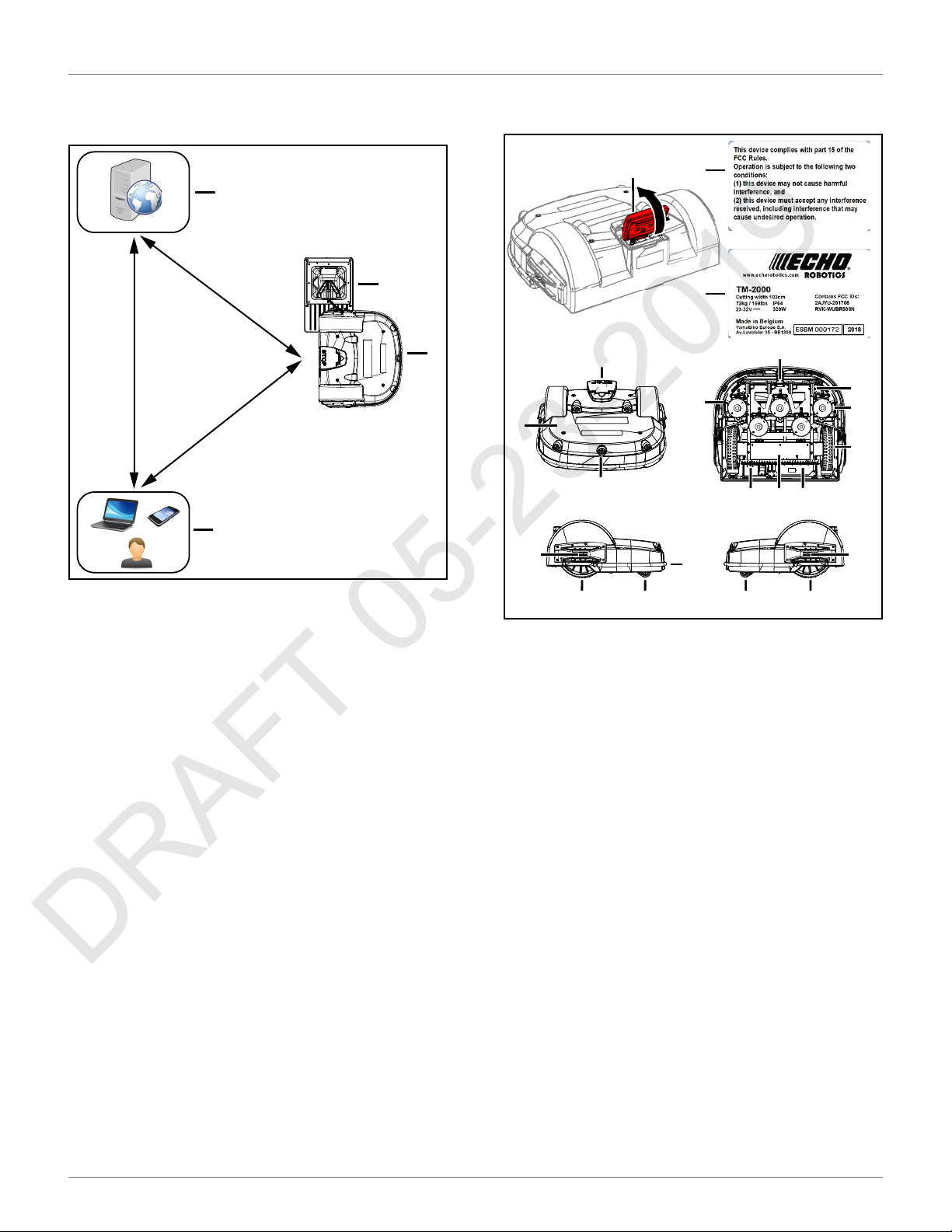
4.1 Robot Components
1
2
4
7
1
5
13
5
2
3
14
6
10
8
151112
7
1 – Charging station
2 – Robot
3 – Internet portal
4 – End user
9
1 – Stop button - Press to stop the robot.
2 – FCC label (lift stop button lid to view)
3 – Serial number label (lift stop button lid to view)
4 – Body
5 – Sonar sensors - Detects object in the path of the robot.
6 – Front wheel
7 – Bumper - A pressure sensor which will cause the robot to
change direction when it touches an obstacle.
8 – Rear wheel
9 – Charge contact- Connects to the charging arm on the charging
station.
10 – Cutting heads - Equipped with three cutting blades.
11 – Li-Ion (Lithium Ion) battery - Supplies power to the robot.
12 – Electrical box - Contains the electronics and the gear drive
motors.
13 – Disc safety guard - A protective guard which inhibits contact
with the cutting heads.
14 – Coil - Detects the magnetic field generated by the peripheral
wires.
15 – Power switch
4
4
9
3
Page 8

SYSTEM COMPONENTS
DRAFT 05-23-2019
ROBOT COMPONENTS
4.1.1 User Interface
Located under the stop button lid.
1 2 3
31 2
4 5
7 9
1 – Numeric buttons - Press to select menu choices and enter
numeric values.
2 – LED screen - Displays the current information.
3 – LED - Indicates the user interface is switched ON.
4 – ON button - Press to turn the user interface ON.
5 – Navigation buttons - Press to highlight menu options.
6 – Back button - Press to exit a menu and return to previous
level.
7 – Accept button - Press to accept an operation or setting.
8 – Service menu button - Press to access the service menu.
9 – Settings menu button - Press to access the settings menu and
define operational settings.
10 – Actions menu button - Press to access the actions menu.
6
8
0
10 9 8 7
X
4.1.2 Cutting Head
1
2
4.1.3 STOP Button
Located on the top of the robot. Press or lift to stop the
robot.
1
4
5
6
1 – Stop button
4.1.4 Obstacle Detection Sensors
Five obstacle detection sonar sensors transmit a sonar
signal of 40 kHz. The sensors allow the robot to detect
and react to obstacles.
Sensors detect obstacles with minimum height of
15.7 in. (400 mm), and a minimum width of 2.0 in.
(50 mm).
When the signal hits an obstacle, it is reflected back to
the sensors. The speed of the robot is reduced to less
than 0.5 mph (0.2 m/s).
ϭ
8
7
6
1 – Bracket unit
2 – Cable gland
3 – Motor case
4 – Blade disc
5 – Anti friction disc
6 – Cutting blade
7 – Lower stay
8 – Upper stay
3
4
ϭ
5
1 – Sensor location
2 – Sensor assembly
When the bumper contacts an object, the robot will
touch the object, stop, move backwards, and by
ϭ
Ϯ
ϭ
ϭ
шϮϬŝŶ
;ϱϬŵŵͿ
шϭϱϳŝŶ
;ϰϬϬŵŵͿ
4
Page 9

SYSTEM COMPONENTS
DRAFT 05-23-2019
ROBOT COMPONENTS
default, turn between 60° and 120°, then continue
moving forward.
4.1.5 Lift Sensors
Each lift sensor is attached to the body and the chassis
of the robot. The two sensors on the front are lift
sensors, the two sensors on the rear are a combination
of lift and body displacement sensors.
If the body is lifted upwards, all functions will stop, and
the robot will remain stationary. If the body is moved
horizontally, the robot will, stop, move backwards, and
by default, turn between 60° and 120°, then continue
moving forward.
1
1
1
1
4.1.6 Coil
Detects the intensity of the magnetic field that is generated by the peripheral wire.
1
1
2
2
2 3
1 – Lift sensor attachment point
2 – Front lift sensor assembly
3 – Rear lift sensor assembly
4.1.7 Tilt / Rollover / and Temperature
Sensors
3
3
These sensors are located on the main circuit board
inside of the electrical box.
The tilt sensor detects the angle of the slope on which
the robot is mowing. If this angle exceeds 30° (58%), an
alarm will be raised and the robot will stop moving.
The rollover sensor detects if the robot has been tipped
upside down, or whether someone is trying to start the
robot when it is upside down.
The temperature sensor measures the ambient
outdoor temperature and will prevent the robot from
operating if this temperature is too low. The minimum
temperature is set as an operating parameter.
5
Page 10

HOW THE ROBOT WORKS
DRAFT 05-23-2019
THE CHARGING STATION
4.2 The Charging Station
2
1
6
8 7
5 How the Robot Works
The robot works in a number of operational states.
Within these states the robot is programmed to
operate in a number of modes.
3
4
5
9
Operational State Description
Autonomous
Mission State
Inactive State
Service State
The robot operates in cycles
in which it mows the grass, or
charges the battery.
The robot can enter an
inactive state if there is a
condition that causes the
Autonomous Mission State to
stop. The robot will return to
the autonomous mission state
when the problem has been
resolved or when a specific
command has been issued.
Initiate this state to access the
Demonstration and
Maintenance Test modes.
1 – Enclosure top
2 – Dust cover
3 – Charging arm
4 – Base
5 – Input panel – Caution label
6 – Serial number location
7 – T-27 Torx® driver
8 – Conduit connector
9 – Tie strap (2X)
5.1 Autonomous Mission State
The robot performs programmed instructions when in
the Autonomous Mission State.
NOTE: Programmed instructions can be over-ridden by
instructions activated from the user interface.
Autonomous
Mission Modes Robot Function
Go zone
Work
Go to charging
station
Charge
Wait in station Remains at the charging station.
Performs a set of maneuvers
before entering the work mode.
Mows the grass in a random
pattern.
Returns to the charging station.
Connects to the charging station
and charges the battery.
6
Page 11
HOW THE ROBOT WORKS
DRAFT 05-23-2019
AUTONOMOUS MISSION STATE
5.1.1 Work Mode
The robot randomly mows the area inside the peripheral wire at a normal mowing speed of 2.2 mph
(1.0 m/s).
1
In an area of long grass the robot will automatically
reduce speed and start mowing in spiral pattern until it
senses that the grass is short. It will then continue in
normal operating mode.
When the robot contacts and obstacle it will maneuver
away from it.
1 – Peripheral wire
When the robot approaches the peripheral wire it
slows down and passes over the wire. The coil senses a
change in phase. This causes the robot to stop, move in
reverse, turn through a defined angle, then continue in
a new direction.
60° - 120°
5.1.2 Go To Charging Station Mode
When working, the robot checks the current conditions
and its programmed instructions. Examples are:
• the battery needs to be charged
• programmed mowing time has ended (for
multi-field installations, this corresponds to the
mowing schedule for the field which the robot is
currently mowing)
• a remote command has been issued
As a result of the condition or programmed instruction,
the robot will return to the charging station and enter
the charge mode.
7
Page 12
HOW THE ROBOT WORKS
DRAFT 05-23-2019
AUTONOMOUS MISSION STATE
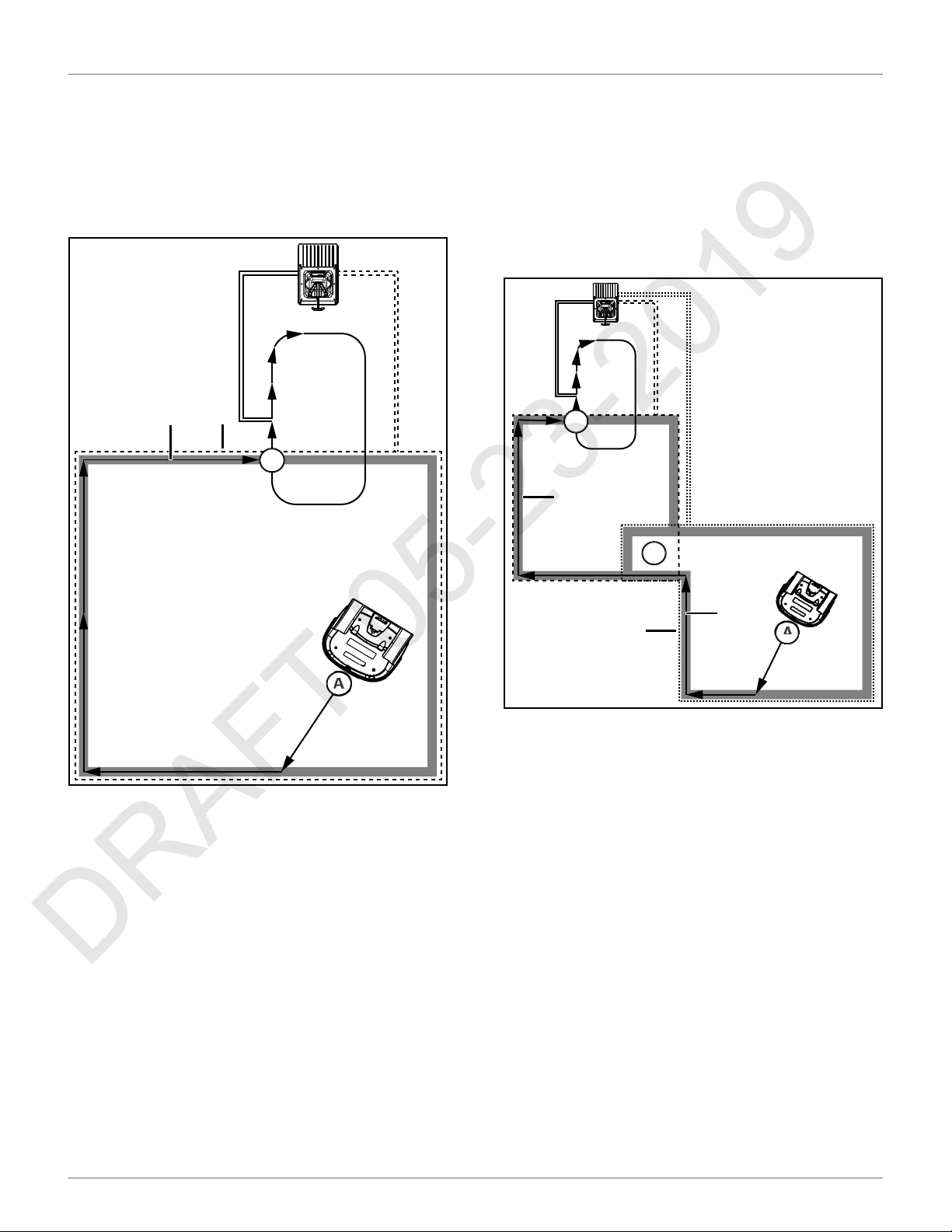
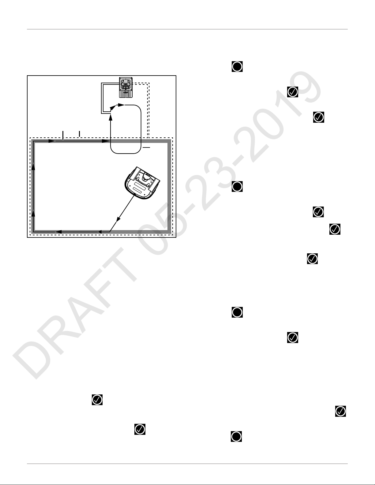
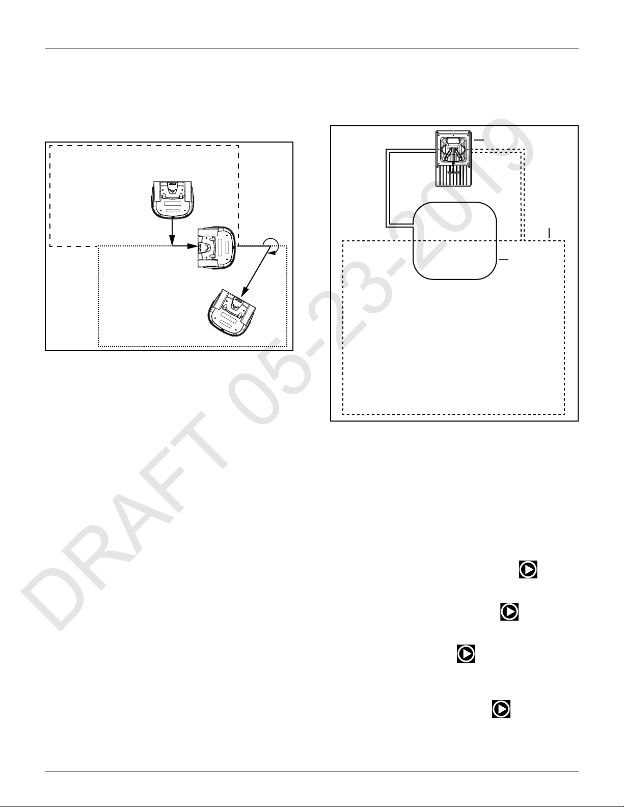
One Field With Station Loop
At Point A, the robot begins a return to the charging
station. It moves to the peripheral wire then follows
the trackborder until it reaches the intersection of the
peripheral and station loop wires (Point B). Then it
follows the station loop wire until it docks at the
charging station.
1
2
B
Two Fields With Station Loop
At Point A, the robot returns to the charging station. It
moves towards the Field 2 peripheral wire and follows
the Field 2 trackborder until it reaches Point B. This is
the area where both fields overlap. It then follows the
Field 1 trackborder until it reaches Point C. This is
where the Field 1 peripheral wire and station loop wire
overlap. Next, the robot follows the station loop wire
until it docks at the charging station.
C
3
1 – Trackborder
2 – Peripheral wire
B
2
1
A
1 – Field 2 / Field 2 peripheral wire
2 – Field 2 trackborder
3 – Field 1 trackborder
A
5.1.3 Charge Mode
In Charge Mode the robot will dock and remain in the
charging station until the battery is fully charged.
The next operations that will be performed depend on
programming and external conditions.
The robot will remain at the charging station if:
• rest periods have been scheduled
• it has been programmed to stay in the station
• the temperature is too low
Otherwise, it will continue with the scheduled mowing
program.
The robot will remain at the charging station once the
battery has been charged until:
8
• the normal program needs to commence
• a specific command is issued
Page 13

HOW THE ROBOT WORKS
DRAFT 05-23-2019
AUTONOMOUS MISSION STATE
5.1.4 Wait In Charging Station Mode
The robot will stay in the charging station once the
battery has been charged until the normal program
needs to commence, or a specific command issued.
5.1.5 Go Zone Mode
The robot will leave the charging station when the
mowing schedule demands it, or a specific command
has been issued.
Go Zone Mode describes the maneuvers the robot
makes to leave the charging station and start mowing.
One Field With Station Loop
This configuration contains one peripheral wire and
one station loop wire.
When the robot leaves the charging station it follows
the station loop wire until it reaches Point A. This is a
predefined distance along the field peripheral wire. At
Point A, the robot will follow the trackborder of the
field until it reaches Point B. At Point B, the robot will
turn into the field and start mowing. The distance traveled along the trackborder and the angle at which the
robot turns into the field are specified in the StartZone
parameters for the field to be mowed.
Two Fields With Station Loop
This configuration contains a peripheral wire for each
field and one station loop wire.
Before leaving the charging station the robot will determine which field to start mowing. This will depend on
the defined mowing schedule for each field. If the
schedule dictates that a specific field must be mowed
at this time, the robot will start mowing in that field.
If there are no schedule constraints, the robot will
choose the field based on the percentage values. Over
a period of time the robot ensures that it starts in each
field according the defined proportions.
When the robot leaves the charging station it follows
the station loop wire until it reaches Point A. At Point A,
the robot will turn and follow the trackborder of Field
1, until it reaches Point B. Point B is where the two
fields overlap.
When the robot is in Field 2, it will travel for a certain
distance along the Field 2 trackborder until it reaches
Point C. At Point C, the robot will turn into the field and
start mowing. The distance traveled along the Field 2
trackborder, and the angle at which the robot turns
into Field 2, are specified in the StartZone parameters
for Field 2.
A
A
B
1 – Field 1 trackborder
2 – Field 2 trackborder
1
C
B
2
9
Page 14
INSTALLATION
DRAFT 05-23-2019
INACTIVE MODES
5.1.6 Demonstration Mode
Use this mode to demonstrate the performance of the
robot before installation of the peripheral wire.
OPERATIONAL HAZARD
The robot will ignore the electromagnetic field generated by the peripheral wire when operating in
demonstration mode.
• Do not leave the robot unsupervised when it is
operating in demonstration mode.
5.2 Inactive Modes
The Alarm Mode and Standby Mode will cause the
robot to enter an inactive mode.
5.2.1 Alarm Mode
When the robot encounters a problem it will register
an alarm and enter the inactive mode. When the cause
for the alarm has been corrected, the user can manually clear the alarm and the robot will then enter the
Standby mode. If no intervention takes place, the robot
will turn off and enter the OFF mode.
5.2.4 OFF Mode
The robot will be in the OFF mode when:
• it has been manually switched OFF
• an alarm situation has not been corrected after a
certain period of time
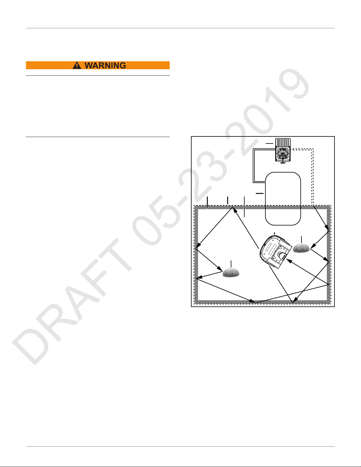
6 Installation
The figure below illustrates the components of a single
field installation.
4
7 3 2
6
1
5
5.2.2 Standby Mode
The robot will enter the Standby mode if:
• the autonomous mission has been stopped due
to an external command
• an alarm situation has been corrected and the
alarm cleared by manual intervention
• it is manually switched ON
The robot will leave the Standby mode when a
command is issued. It will then enter the Self Test
Mode before recommencing any activity.
5.2.3 Self Test Mode
Whenever the robot has been in the Standby Mode it
will perform a self test to check the integrity of the
entire system (including electronics, sensors,
mechanics and software). When the result of the self
test is successful, it will resume the autonomous
working state. If the result of the self test is not
successful, it will register an alarm.
1 – Robot
2 – Mowing area
3 – Peripheral wire
4 – Charging station
5 – Obstacle
6 – Station loop wire
7 – Trackborder
Only install the system on a field with a slope that is less
than or equal to 17°. If the slope is near the peripheral
wire, program the robot to return to the charging
station by descending the slope.
5
10
Page 15
INSTALLATION
DRAFT 05-23-2019
STATION LOOP WIRE INSTALLATION
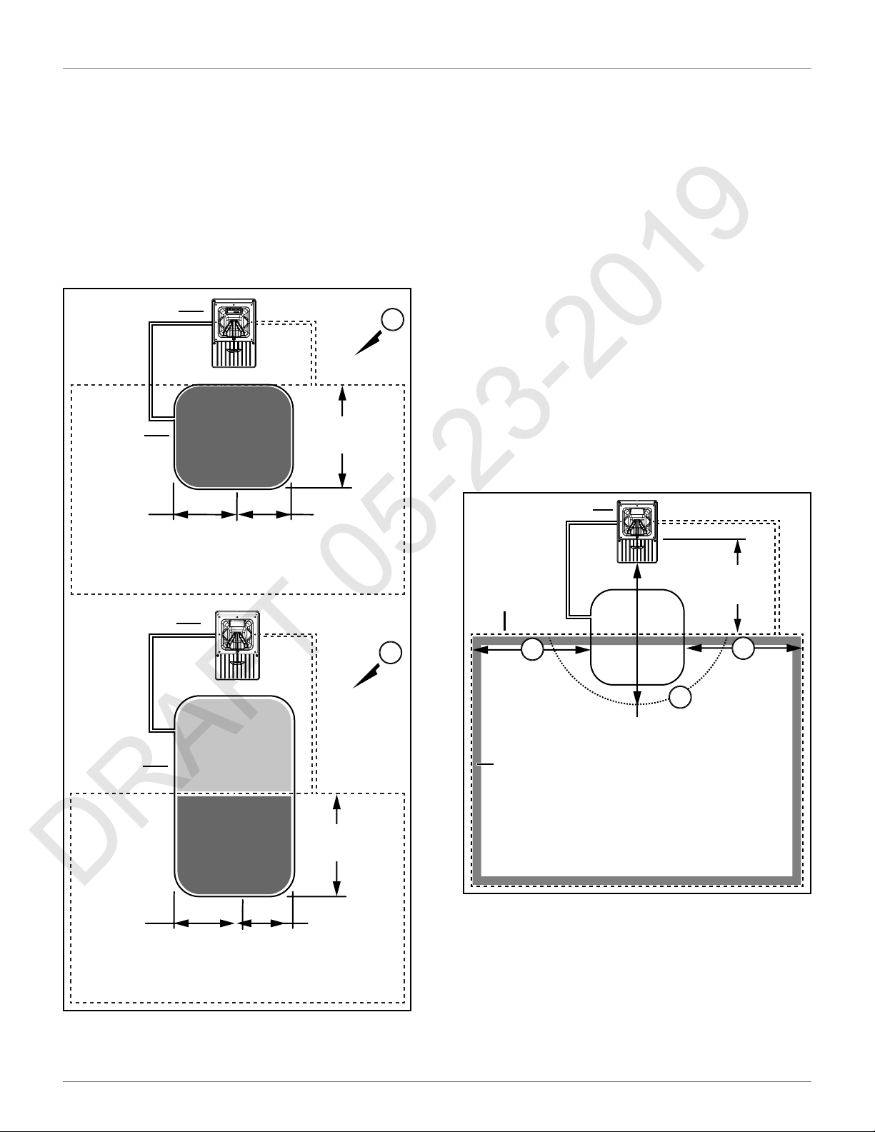
6.1 Station Loop Wire
Installation
The station loop wire can be installed completely inside
of the field (Figure A), or partially inside of the field
(Figure B). The wire must extend a minimum of
13 ± 1.6 ft. (4.0 ± 0.5 m) into the field.
The distance between the center of the charging
station and the end of the station loop wire is 8.2 ft.
(2.5 m) maximum.
2
1
ϭϯцϭϲŌ
(4 ± 0.5 m)
A
6.2 Peripheral Wire Installation
IMPORTANT: Only use peripheral wire which is
supplied by ECHO Inc.
Each end of a peripheral wire is connected to the
charging station.
Install the peripheral wire in a clockwise direction
around the field. Do not cross or form loops with the
peripheral wire.
Minimum peripheral wire length is 656 ft. (200 m). If
this minimum length is not possible, install an inductor
in series with the peripheral wire. See the ECHO
Robotics Parts Catalog for inductor kit information.
Maximum peripheral wire length is 3937 ft. (1,200 m).
Use a second charging station when:
• total length of the peripheral wire (including
islands and pseudo-islands) exceeds 3,281 ft.
(1,000 m)
• more than five obstacles are on the trackborder
Peripheral wire installation dimensions:
ϴϮŌ
(2.5 m)
ϴϮŌ
(2.5 m)
ϴϮŌ
(2.5 m)
1
2
B
1
ϭϯцϭϲŌ
(4 ± 0.5 m)
ϴϮŌ
(2.5 m)
1 – Peripheral wire
2 – Charging station
3 – Recommended length incoming side
4 – Recommended length outgoing side
5 – Obstacle free zone
6 – Trackborder
3
ϭϲϰŌ
(5.0 m)
6
2
ϯϵϰŌ
(12.0 m)
5
28.3 in.
(720 mm)
4
ϭϲϰŌ
(5.0 m)
1 – Station loop wire
2 – Charging station
11
Page 16
INSTALLATION
DRAFT 05-23-2019
PERIPHERAL WIRE INSTALLATION OFFSETS
Peripheral wire installation angles must be greater
than or equal to 90°, with a radius greater than or equal
to 3.3 ft. (1.0 m).
ϭ
ϭ
шϯϯŌ
;шϭŵͿ
шϵϬΣ
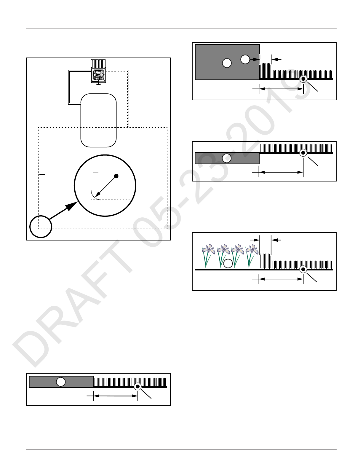
Raised hard landscaping:
1
(750 mm)
1 – Terrace / Path / Wall
2 – Peripheral wire
3 – Area not mowed
Hard landscaping level with grass:
1
(300 mm)
1 – Terrace / Path
2 – Peripheral wire
NOTE: A path that crosses the field to be mowed should
be level with the grass.
Lawn-level planting:
3
29.5 in.
11.8 in.
9.5 in.
(240 mm)
2
2
3.5 in.
(90 mm)
2
1 – Peripheral wire
The peripheral wire needs to take obstacles into
account. Some obstacles can be detected by the sonar
sensors on the robot, others require specific placement
of the peripheral wire, or the use of islands or
pseudo-islands.
6.3 Peripheral Wire Installation
3
1
29.5 in.
(750 mm)
1 – Flower bed
2 – Peripheral wire
3 – Area not mowed
Offsets
NOTE: The dimensional values shown apply when the
“Wire crossing distance” parameter is at the default
setting of 0.2 m.
Rough grass that does not need to be mowed:
1
20 in.
(510 mm)
1 – Rough grass
2 – Peripheral wire
2
12
Page 17
6.4 Sites Containing Narrow
DRAFT 05-23-2019
Straits
These sites require specific installation of the peripheral wire.
The required minimum width of the strait, depends on
the length of the strait. If this minimum width is not
available when the robot is in Zone B, it will not be able
to pass through the strait and return to the charging
station. In this case, installation of an additional
charging station in Zone B is required.
2
3
Zone B
Zone A
1
4
INSTALLATION
SITES CONTAINING NARROW STRAITS
2
1
3
1 – Narrow strait
2 – Peripheral wire
3 – Minimum distance between peripheral wire
4 – Length of strait
The table below presents the minimum distance
between wires required to enable the robot to follow
its trackborder from Zone B through the strait and
return to the charging station in Zone A.
6.5 Sites With Long Lanes
A long lane represents an area where a minimum
distance for the installation of the peripheral wire is
required. If this minimum distance is not met, the robot
may not be able to detect the peripheral wire. If the
peripheral wire is not detected, the robot cannot
return to the charging station to charge its battery.
1 – Lane
2 – Peripheral wire
3 – Minimum distance between peripheral wire
If the length of the lane is less than 49.2 ft. (15 m), then
the minimum distance between the peripheral wire
must be greater than 32.8 ft. (10 m).
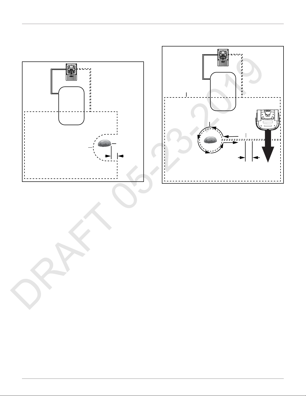
6.6 Obstacles
Obstacles are objects that the robot must avoid. Examples are:
• trees, flower beds
• swing sets, climbing frames, trampolines
• sidewalks, walking paths, terraces
• ponds, swimming pools
Some obstacles are detected by the sonar sensors on
the robot. Other obstacles require the installation of
the peripheral wire to create an island, or a
pseudo-island.
If an island is created, the robot will not approach the
obstacle. The robot will move across the peripheral
wire to avoid the obstacle.
If a pseudo-island is created, the robot will approach
the obstacle, and then maneuver around it.
Obstacles Near the Boundary to be Mowed
13
Page 18
INSTALLATION
DRAFT 05-23-2019
ISLANDS
If an obstacle is less than 3.3 ft. (1.0 m) from the
boundary, install the peripheral wire around the
obstacle. If the distance between the obstacle and the
boundary is greater than 3.3 ft. (1.0 m), but less than
16.4 ft. (5.0 m), install a pseudo-island.
2
1
ϯϯŌ
(1.0 m)
• secure with tie straps at 0.4 in. (10 mm) increments
3
2
5
1
x x x x
4
0.4 in.
(10 mm)
1 – Obstacle
2 – Peripheral wire
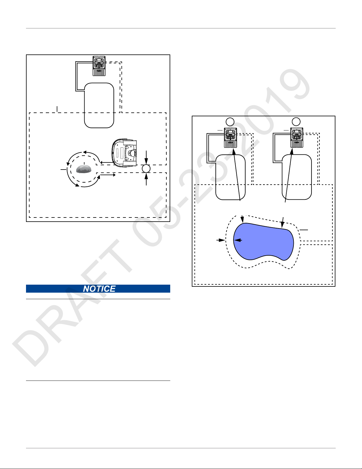
6.7 Islands
Create an island when an obstacle is more than:
• 16.4 ft. (5.0 m) from the peripheral wire
• 49.2 ft. (15.0 m) from the charging station
• 16.4 ft. (5.0 m) from another island or
pseudo-island
Install the peripheral wire around an obstacle to create
an island. A maximum of five islands can be installed.
Installation requirements for an island:
• counterclockwise direction around an object
• place the approach and return sides of the
peripheral wire directly next to each other (do
not cross or twist the wire)
1 – Obstacle
2 – Direction to install peripheral wire
3 – Peripheral wire
4 – Movement of robot
5 – Tie strap locations
Create a pseudo island when an obstacle is less than:
• 16.4 ft. (5.0 m) from the peripheral wire
• 49.2 ft. (15.0 m) from the charging station
• 16.4 ft. (5.0 m) from another island or
pseudo-island
Install the peripheral wire around an obstacle to create
a pseudo-island.
Installation requirements for a pseudo-island:
• counterclockwise direction around an object
• allow a fixed distance of 15.7 - 23.6 in.
(400 - 600 mm) between the approach and
return sides
14
Page 19
INSTALLATION
DRAFT 05-23-2019
WATER OBSTACLE
• do not cross or twist the approach and return
side of the peripheral wire
3
1
2
15.7 - 23.6 in.
(400 - 600 mm)
4
Install the charging station a minimum of 49.2 ft. (15 m)
from the edge of the water.
Two possible installations for the charging station are
shown in the figure below.
NOTE: The robot should return to the charging station
from the direction away from the water.
If the charging station is located at Point A, program the
robot to return to it in a clockwise direction. If the
charging station is located at Point B, program the
robot to return to it in a counterclockwise direction.
A
2 2
хϰϵϮŌ
(>15.0 m)
хϰϵϮŌ
(>15.0 m)
B
1 – Obstacle
2 – Direction to install peripheral wire (and movement of robot)
3 – Peripheral wire
4 – Fixed distance between approach and return sides
хϱϯŌ
(>1.6 m)
1
6.8 Water Obstacle
1 – Peripheral wire
2 – Charging station
WATER AMPLIFIES THE ELECTROMAGNETIC SIGNAL OF THE PERIPHERAL
WIRE
The robot is attracted towards higher signal levels.
Failure to correctly avoid a water obstacle can result in submersion of the robot.
• Use an island or a pseudo-island to avoid a water obstacle.
Install the peripheral wire a minimum distance of
5.3 ft. (1.6 m) from the edge of the water. Increase this
distance if the ground slopes towards the water, is slippery, or can become wet or flooded.
If meeting the minimum distance of 5.3 ft. (1.6 m) is not
possible, install a physical barrier around the water.
6.9 Sloped Fields
The maximum slope on any part of the field must be
less than or equal to 17°.
If a sloping part of the field is well away from the
peripheral wire, no specific programming of the robot
is required. If the sloping part of the field is near the
peripheral wire, program the robot to return to the
charging station by descending the slope.
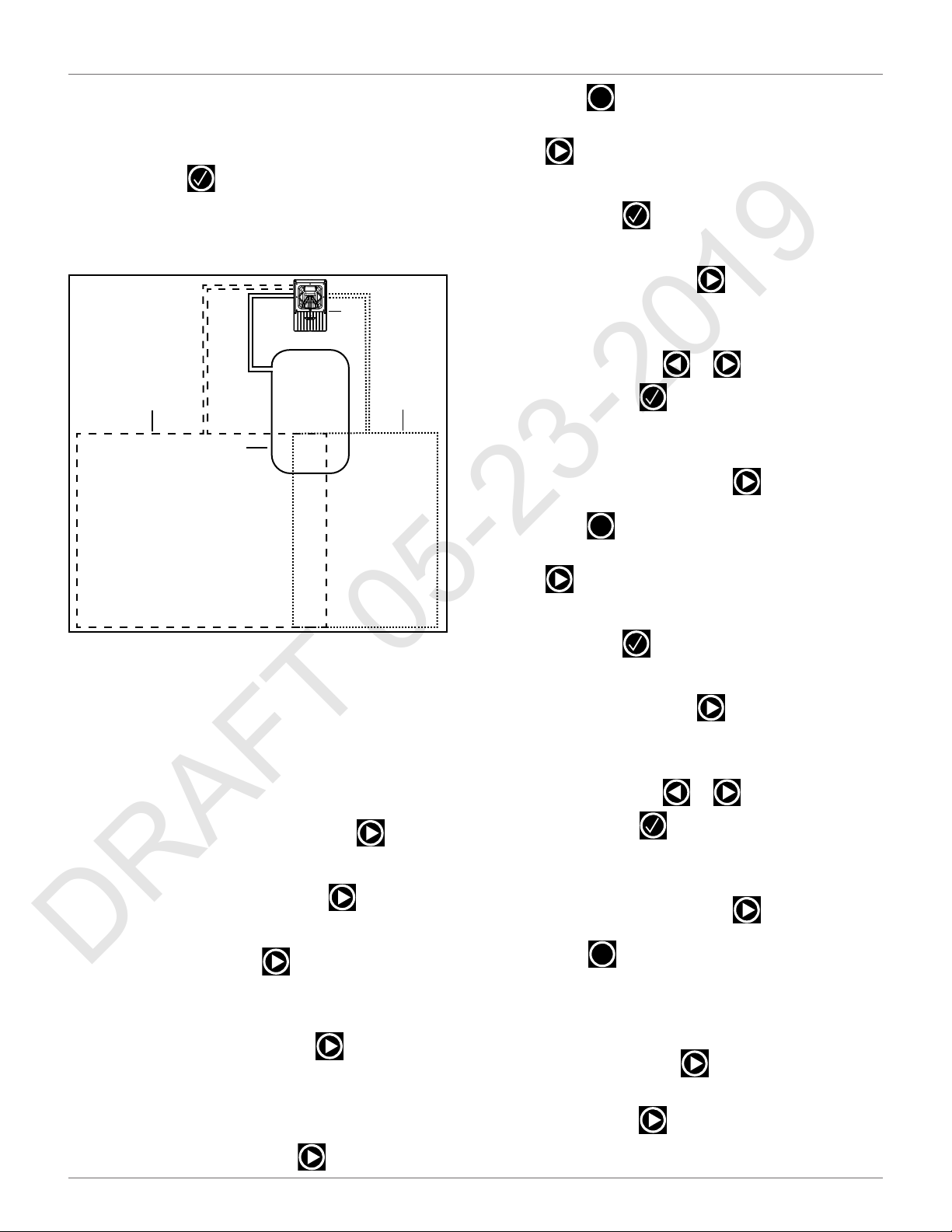
This example describes how to configure a station loop
wire to return the robot to the charging station. There
is one wire that defines the area to be mowed; this wire
is named "Field", the additional wire is named "Loop".
The “Field” wire is the peripheral wire. The “Loop” wire
is the station loop wire.
15
Page 20
INSTALLATION
DRAFT 05-23-2019
CONFIGURATION
The "Field" wire is configured for the robot to mow
normally. When it returns to the charging station it will
follow the trackborder until it reaches the "Loop" wire.
It will then follow the “Loop” wire until it reaches the
charging station.
2
3
1
6) Check the value shown at the top of the screen.
This should be positive. If it is not, select Reverse
phase and check the button ON.
7) Press twice to return to the Infrastructure
menu.
8) Select Parcels, then press . Select the parcel
associated with the LOOP wire.
9) Select Return direction, then press . Choose
whether you want the robot to return in a clockwise or counterclockwise direction.
10) Disable the use of the trackborder. Select Use
trackborder and check the button OFF. This
ensures that when the robot is in this field, it will
just follow the wire to reach the station.
11) Press twice to return to the Infrastructure
menu.
X
X
1 – Station loop wire (“Loop”)
2 – Peripheral wire (“Field”)
3 – Trackborder
When installing the wire for the "lawn" loop all the
conditions described must be respected. This includes
the conditions required for multi-fields.
6.10 Configuration
Configuration of this installation is completed through
the through User Interface. The instructions given
below are the minimum set of configuration parameters that must be set for this type of installation.
1) Press and hold 9 on the user interface screen
until the technician's menu appears.
2) Select Infrastructure > Peripheral wires.
3) On the "Wire settings" screen, select Wire
CH{X},then press .
12) Select Create new wire, then press .
13) Select the newly created wire, then press .
14) Rename this field to LAWN.
15) Select Signal channel, then press Assign the
channel number for the large field to be mowed.
16) Check the value shown at the top of the screen.
This should be positive. If it is not, select Reverse
phase and check the button ON.
17) Press twice to return to the Infrastructure
menu.
18) Select Parcels, then press . Select the parcel
associated with the LAWN wire.
19) Set the Return direction to the same as above.
20) Select Use trackborder and check the button ON.
This ensures that when the robot is in this field, it
will follow the trackborder until it reaches the
LOOP field.
X
4) Rename this Wire to LOOP.
5) Select Signal channel, then press . Assign the
channel number for the station loop.
21) Select Neighboring parcels, then press .
Check the button next to the LOOP parcel.
22) Press to exit this menu.
X
16
Page 21
INSTALLATION
DRAFT 05-23-2019
OVERLAPS
23) Select Edit parcels percentage, then press .
Set the value to 100% for the lawn parcel.
24) Press to return to the Infrastructure menu.
25) Select Infrastructure > Stations > Create new
station, then press .
26) A name is generated that you can modify if you
want.
27) Select Connected to parcels, then press .A
list of parcels is presented. Select the parcel
inside the LOOP wire and check the button ON.
28) Select Station inside parcel's wire. Check the
button ON if the station is inside the LOOP wire.
In the example shown above it is outside the
wire.
Connect a total of one station loop and two peripheral
wires to a single charging station.
• Each field is defined by a peripheral wire that
starts and ends at the charging station.
• Each peripheral wire is assigned to a different
signal channel in the charging station.
• The charging station must contain one signal
channel board for every peripheral wire
required.
• The area inside of each peripheral wire is defined
as a field. Each peripheral wire must overlap with
its neighboring one.
• Each pair of wires which overlap must be designated as neighboring fields.
X
The elements of a multiple field installation are shown
in the following figure.
2
2
1 – Station loop wire / Field 1
2 – Peripheral wire 2 / Field 2
3 – Peripheral wire 3 / Field 3
4 – Overlap area
1
4
3
3
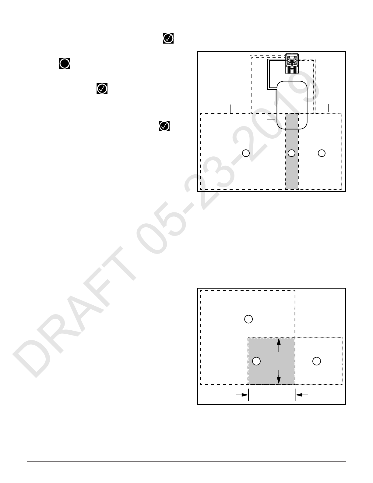
6.11 Overlaps
An overlap is an area that lies within two fields and is
used for the robot to transition from one field to
another. The length and width of the overlap must be
greater than 9.8 ft. (3 m).
Station loop wire 1 / Field 1, is the small wire to which
the charging station is connected. In this example it
overlaps the larger peripheral wires and fields. When in
this field, the robot will not use the trackborder, it will
follow the station loop wire to enter the charging
station.
All three fields are neighbors to each other.
The overlap area is a transition zone used to connect
the main mowing areas of the fields.
The proportion of time that the robot spends mowing
in fields 1 and 2 is determined by the percentage values
assigned to the corresponding fields. For the station
loop field, the percentage can be set to 0.
хϵϴŌ
(> 3.0 m)
1 – Overlap area
2 – Field 1
3 – Field 2
2
хϵϴŌ
1
(> 3.0 m)
3
17
Page 22
INSTALLATION
DRAFT 05-23-2019
MULTI-FIELD PERIPHERAL WIRE INSTALLATION
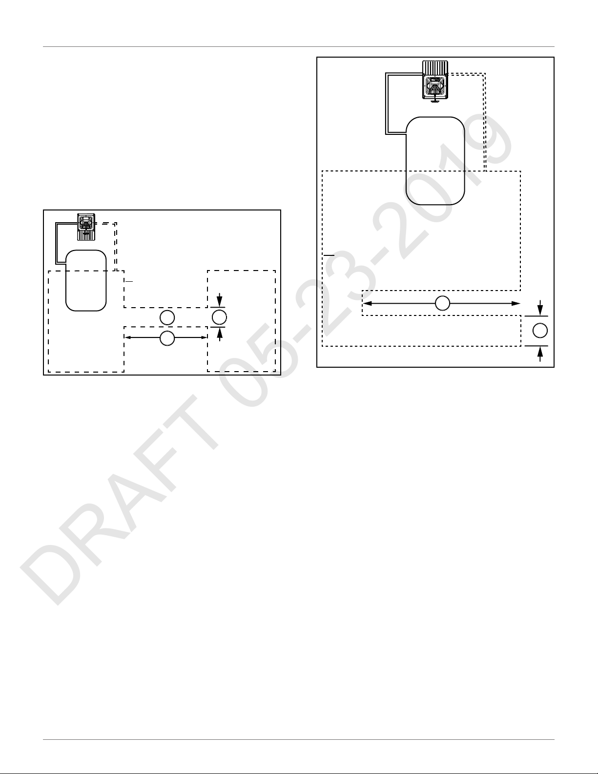
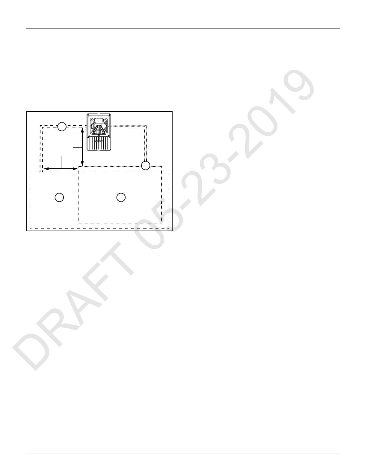
6.12 Multi-Field Peripheral Wire
Installation
The start and finish sides of the peripheral wire must lie
next to each other when they enter the charging
station. Install the start and finish sides of the peripheral wire for one field around the other field. The
distance between the peripheral wires for each field
must be greater than or equal to 23.6 in. (600 mm).
1
шϮϯϲŝŶ
;шϲϬϬŵŵͿ
Ϯ
ϯ4
7) If the installation is a multi-field installation,
define the start zone parameters for a parcel.
8) Select Infrastructure > Stations.
9) Select Create new station.
10) Select Connected to parcels and connect the
station to the loop parcel.
11) Select Station Inside Parcel's Wire and specify
whether the station is on the inside or the
outside of the station loop wire.
6.13.2 Start Zones
Start zones define where and how the robot starts
mowing.
• A start zone is defined for a parcel.
• Multiple start zones can be defined for the same
wire/parcel.
The Start Zone screen displays the following:
List of defined start zones
1 – Start and finish side of Field 1 peripheral wire
2 – Start and finish side of Field 2 peripheral wire
3 – Field 2
4 – Field 1
6.13 Configuration
Once the peripheral wire(s) and the charging station
have been set in place, the installation needs to be
configured.
Access the User Interface to configure single and
multi-field installations.
6.13.1 General Configuration Procedure
Using a Station Loop
1) Open the technician's menu.
2) Select Infrastructure > Peripheral wires and
create the required number of wires for the
installation.
For each one the line below shows some characteristics
of the zone.
Create new start zone
Enables you to create a new zone with all the properties listed below.
6.13.3 Start Zone Properties
Following from
This option appears if you are defining a start zone for
station with a positioning beacon. It specifies the parcel
in which the start zone is implemented.
For a multi-field installation, you can specify the
specific parcel.
Default means coming from any other parcel.
Coming from
This option appears if you are defining a start zone for
a parcel.
It defines the parcel preceding the one in which the
start zone will be implemented.
3) For each wire assign the channel number and
check the reverse phase.
4) Select Infrastructure > Parcels.
5) Define the properties of the parcel that is associated with each wire.
6) Create new parcels if necessary.
18
Percentage
Allows you to edit the percentages applied to different
parcels.
If only one parcel is defined this value must be set to
100%.
Page 23
INSTALLATION
DRAFT 05-23-2019
CONFIGURATION
Do not edit the percentage until more than one start
zone has been defined.
Edit percentage
Allows you to edit the percentages applied to different
parcels.
If only one parcel is defined this value must be set to
100%.
Do not edit the percentage until more than one start
zone has been defined.
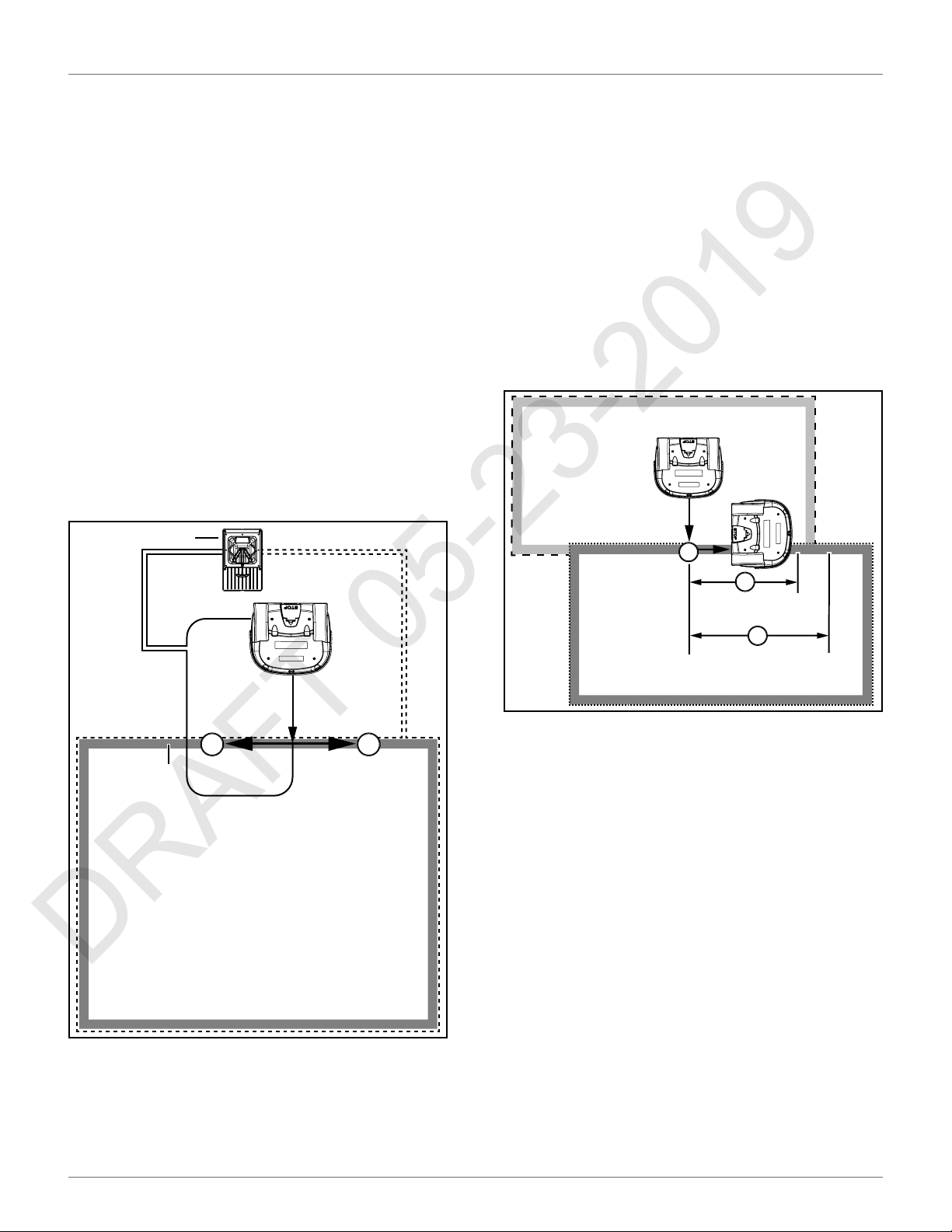
Direction
This specifies the clockwise or counterclockwise direction the robot will take to move along the trackborder
after leaving the charging station.
When the robot leaves the charging station, it follows
the station loop wire for a predefined distance until it
arrives in the trackborder of a mowing field, it then
takes the specified direction.
2
Distance Min. / Distance Max.
This is the distance that the robot will travel along the
trackborder after leaving the station before starting
mowing. A random value between the minimum and
maximum values will be selected.
Distance Min. and Distance Max. are measured from
the point where the robot enters the parcel, if this
differs from the one in which the charging station is
located.
If the start zone is located in a different parcel than the
one containing the charging station, the distances are
measured from the entry point into the parcel (shown
in the figure below).
3
1
2
1 – Distance Min.
5
3
4
2 – Distance Max.
3 – Trackborder
1 – Charging station
2 – Station loop wire
3 – Trackborder
4 – Clockwise direction on trackborder
5 – Counterclockwise direction on trackborder
19
Page 24
INSTALLATION
DRAFT 05-23-2019
CONFIGURATION EXAMPLES
Angle Min. / Angle Max.
This is the angle that the robot will turn through to take
it into the field to start mowing. Minimum and
maximum values are defined and the robot will choose
a random value between the defined limits.
6.14 Configuration Examples
6.14.1 Wire Configuration - One Zone
Installation
1
3
2
Delete StartZone
Allows the start zone to be deleted.
1 – Charging station
2 – Station loop wire
3 – Peripheral wire
Access the User Interface to set the following parameters.
Peripheral Wire Configuration
1) Press and hold 9 on the numeric keypad until the
technician’s menu appears.
2) The TECHNICIAN SETTING menu will display.
Select 1. Infrastructure, then press .
3) The INFRASTRUCTURE menu will display. Select
1. Peripheral wires, then press .
4) The WIRES SETTINGS menu will display. Select 1.
Wire CH0, then press .
5) The WIRE CH0: NO SIGNAL menu will display.
Select the numeric option next to Signal channel,
set the value to 0, then press .
NOTE: The station loop wire will always be set to 0.
20
Page 25
INSTALLATION
DRAFT 05-23-2019
CONFIGURATION EXAMPLES
6) Check the value shown at the top of the screen.
The value should be positive, if it is not, select
Reverse phase, then press .
7) Press once, the WIRES SETTINGS menu will
display. Select 9. Create new wire, then press
8) The VALIDATE screen will display. Select OK,
then press .
9) The WIRES SETTINGS menu will display. Select
Wire CH5, then press .
10) The Wire CH5: No Signal screen will display.
Select the numeric option next to SIGNAL
CHANNEL, press or and set the value to
1, then press .
11) Check the value shown at the top of the screen.
The value should be positive, if it is not, select
Reverse phase, then press .
X
.
6) The FIELD screen will display. Select Use Track-
border, then press .
7) Scroll down to 8. Neighboring parcels, then press
.
8) The NEIGHBORING PARCELS screen will display.
Select LOOP, then press . Select Confirm,
then press .
9) The FIELD screen will display. Press twice to
return to the INFRASTRUCTURE screen.
Station Configuration
Select 3. Stations, then press .
1)
2) Select 9. Create manual station, then press .
3) The VALIDATE screen will display. Select OK,
then press .
4) The Manual Station 1 screen will display. Select
Connected to parcels, then press .
X
12) Press twice to return to the INFRASTRUCTURE screen.
Parcels Configuration
1) From the INFRASTRUCTURE menu, select
Parcels, then press .
2) The PARCELS menu will display. Select 1. Parcel
1, then press .
3) The Parcel 1 menu will display. Parcel 1 will be
highlighted, press . Use , , , or
select V (located in the bottom row), then press
4) Press once to return to the PARCELS screen.
5) Select Parcel 2, then press . Use , ,
renaming, select V (located in the bottom row),
then press .
X
, rename Parcel 1 to LOOP. After renaming,
.
X
, or , rename Parcel 2 to Field. After
5) The VALIDATE screen will display. Select OK,
then press .
6) The Connected Parcels screen will display. The
option for Wire CH0 will be highlighted. Press
to change it to LOOP, then press .
7) Press once to return to the Manual Station
screen.
8) Select Station inside parcel’s wire. Press if
the charging station is inside of the station loop
wire.
9) Press twice to return to the INFRASTRUC-
TURE screen.
10) Press twice, the Waiting for new mission
screen will display.
11) Press once, the SERVICE SETTINGS screen
will display. Select 3. Operations, then press .
12) The OPERATIONS screen will display. Select Edit
X
X
X
parcels percentage, then press .
21
Page 26
INSTALLATION
DRAFT 05-23-2019
CONFIGURATION EXAMPLES
13) The PARCELS PERCENTAGE screen will display.
Select the numeric option next to LOOP, set the
number to O. Select the numeric option next to
FIELD, set the number to100. Select CONFIRM,
then press .
6.14.2 Wire Configuration - Two Zone
Installation
1
3
2
4
7) Press once, the WIRES SETTINGS menu will
display. Select 9. Create new wire, then press
8) The VALIDATE screen will display. Select OK,
then press .
9) The WIRES SETTINGS menu will display. Select
Wire CH5, then press .
10) The Wire CH5: No Signal screen will display.
Select the numeric option next to SIGNAL
CHANNEL, press or and set the value to
1, then press .
11) Check the value shown at the top of the screen.
The value should be positive, if it is not, select
Reverse phase, then press .
12) Press once, the WIRES SETTINGS menu will
display. Select 9. Create new wire, then press
X
.
X
13) The VALIDATE screen will display. Select OK,
1 – Charging station
2 – Station loop wire
3 – Field Zone 1 peripheral wire
4 – Field Zone 2 peripheral wire
Peripheral Wire Configuration
1) Press and hold 9 on the numeric keypad until the
technician’s menu appears.
2) The TECHNICIAN SETTING menu will display.
Select 1. Infrastructure, then press .
3) The INFRASTRUCTURE menu will display. Select
1. Peripheral wires, then press .
4) The WIRES SETTINGS menu will display. Select 1.
Wire CH0, then press .
5) The WIRE CH0: NO SIGNAL menu will display.
Select the numeric option next to Signal channel,
set the value to 0, then press .
NOTE: The station loop wire will always be set to 0.
6) Check the value shown at the top of the screen.
The value should be positive, if it is not, select
then press .
14) The WIRES SETTINGS menu will display. Select
Wire CH5, then press .
15) The Wire CH5: No Signal screen will display.
Select the numeric option next to SIGNAL
CHANNEL, press or and set the value to
2, then press .
16) Check the value shown at the top of the screen.
The value should be positive, if it is not, select
Reverse phase, then press
17) Press twice to return to the INFRASTRUC-
TURE screen.
Parcels Configuration
1) From the INFRASTRUCTURE screen, select
Parcels, then press .
2) The PARCELS menu will display. Select 1. Parcel
1, then press .
X
Reverse phase, then press .
22
Page 27
INSTALLATION
DRAFT 05-23-2019
CONFIGURATION EXAMPLES
3) The Parcel 1 menu will display. Parcel 1 will be
highlighted, press . Use , , , or
, rename Parcel 1 to LOOP. After renaming,
select V (located in the bottom row), then press
.
4) Press once to return to the PARCELS screen.
5) Select Parcel 2, then press . Use , ,
renaming, select V (located in the bottom row),
then press .
6) The FIELD 1screen will display. Select Use Track-
border, then press .
7) Press once to return to the PARCELS screen.
8) Select Parcel 3, then press . Use , ,
renaming, select V (located in the bottom row),
X
, or , rename Parcel 2 to Field 1. After
X
, or , rename Parcel 3 to Field 2. After
Station Configuration
1) Select 3. Stations, then press .
2) Select 9. Create manual station, then press .
3) The VALIDATE screen will display. Select OK,
then press
4) The Manual Station 1 screen will display. Select
Connected to parcels, then press .
5) The VALIDATE screen will display. Select OK,
then press .
6) The Connected Parcels screen will display. The
option for Wire CH0 will be highlighted. Press
to change it to LOOP, then press .
7) Press once to return to the Manual Station
screen.
8) Select Station inside parcel’s wire. Press if
the charging station is inside of the station loop
wire.
X
.
then press .
9) The FIELD 2 screen will display. Select Use Track-
border, then press .
10) Scroll down to 8. Neighboring parcels, then press
.
11) The NEIGHBORING PARCELS screen will display.
Scroll down to select LOOP, then press .
Scroll down to Confirm, then press .
12) Press once to return to the PARCELS screen.
13) Scroll down to Field 1, then press .
14) Scroll down to Neighboring parcels, then press
X
.
9) Press twice to return to the INFRASTRUC-
TURE screen.
10) Press twice, the Waiting for new mission
screen will display.
11) Press once, the SERVICE SETTINGS screen
will display. Select 3. Operations, then press .
12) The OPERATIONS screen will display. Select Edit
parcels percentage, then press .
13) The PARCELS PERCENTAGE screen will display.
Select the numeric option next to LOOP, set the
number to O. Select the numeric option next to
FIELD, set the number to100. Select CONFIRM,
then press .
X
X
6.14.3 Single Field With Two Start Zones
15) The NEIGHBORING PARCELS screen will display.
Scroll down to select LOOP, then press .
Scroll down to Confirm, then press .
16) The FIELD screen will display. Press twice to
return to the INFRASTRUCTURE screen.
X
This is an example of an installation that might be used
in a large field with two areas. Even though it is set up
as a single field, two start zones are used to ensure that
the robot starts mowing in both areas on a regular
basis.
23
Page 28

INSTALLATION
DRAFT 05-23-2019
CONFIGURATION EXAMPLES
The layout of the installation is shown in the figure
below.
3
1
>16.4 ft.
(>5 m)
2
7) Press once, the WIRES SETTINGS menu will
display. Select 9. Create new wire, then press
8) The VALIDATE screen will display. Select OK,
then press .
9) The WIRES SETTINGS menu will display. Select
Wire CH5, then press .
10) The Wire CH5: No Signal screen will display.
Select the numeric option next to SIGNAL
CHANNEL, press or and set the value to
1, then press .
11) Check the value shown at the top of the screen.
The value should be positive, if it is not, select
Reverse phase, then press .
12) Press twice to return to the INFRASTRUC-
TURE screen.
X
.
X
1 – Start zone 1
2 – Start zone 2
3 – Peripheral wire
Access the User Interface to set the following parameters.
Peripheral Wire Configuration
1) Press and hold 9 on the numeric keypad until the
technician’s menu appears.
2) The TECHNICIAN SETTING menu will display.
Select 1. Infrastructure, then press .
3) The INFRASTRUCTURE menu will display. Select
1. Peripheral wires, then press .
4) The WIRES SETTINGS menu will display. Select 1.
Wire CH0, then press .
5) The WIRE CH0: NO SIGNAL menu will display.
Select the numeric option next to Signal channel,
set the value to 0, then press .
NOTE: The station loop wire will always be set to 0.
6) Check the value shown at the top of the screen.
The value should be positive, if it is not, select
Reverse phase, then press .
Parcels Configuration
1) From the INFRASTRUCTURE menu, select
Parcels, then press .
2) The PARCELS menu will display. Select 1. Parcel
1, then press .
3) The Parcel 1 menu will display. Parcel 1 will be
highlighted, press . Use , , , or
, rename Parcel 1 to LOOP. After renaming,
select V (located in the bottom row), then press
.
4) Press once to return to the PARCELS screen.
5) Select Parcel 2, then press . Use , ,
renaming, select V (located in the bottom row),
then press .
6) The FIELD screen will display. Select Use Track-
border, then press .
7) Scroll down to 8. Neighboring parcels, then press
X
, or , rename Parcel 2 to Field. After
.
24
Page 29

INSTALLATION
DRAFT 05-23-2019
CONFIGURATION EXAMPLES
8) The NEIGHBORING PARCELS screen will display.
Select LOOP, then press . Select Confirm,
then press .
9) The FIELD screen will display. Scroll down to Start
Zones, then press .
10) The Start Zones screen will display. Press
once.
11) The VALIDATE screen will display. Select OK, then
press .
12) The Start Zones screen will display.
For the Coming from parcel option, DEFAULT is
correct.
For the Direction option, CW is correct.
Set the Distance Min. value.
Set the Distance Max. value.
Set the Angle Min. value (between 0° - 180°).
Set the Angle Max. value (between 0° - 180°).
Station Configuration
1) Select 3. Stations, then press .
2) Select 9. Create manual station, then press .
3) The VALIDATE screen will display. Select OK,
then press
4) The Manual Station 1 screen will display. Select
Connected to parcels, then press .
5) The VALIDATE screen will display. Select OK,
then press .
6) The Connected Parcels screen will display. The
option for Wire CH0 will be highlighted. Press
to change it to LOOP, then press .
7) Press once to return to the Manual Station
screen.
X
.
13) Press once. The Start Zones screen will
display. Scroll down to Create new start zone,
then press .
14) The VALIDATE screen will display, select OK, then
press .
15) The Start Zones screen will display.
For the Coming from parcel option, DEFAULT is
correct.
For the Direction option, CW is correct.
Set the Distance Min. value.
Set the Distance Max. value.
Set the Angle Min. value (between 0° - 180°).
Set the Angle Max. value (between 0° - 180°).
16) Scroll to Edit Percentage, then press .
17) The Edit Percentage screen will display. Set the
Start Zone 2 values to 80%. Set the Start Zone 3
value to 20%. Select CONFIRM, then press .
X
8) Select Station inside parcel’s wire. Press if
the charging station is inside of the station loop
wire.
9) Press twice to return to the INFRASTRUC-
TURE screen.
10) Press twice, the Waiting for new mission
screen will display.
11) Press once, the SERVICE SETTINGS screen
will display. Select 3. Operations, then press .
12) The OPERATIONS screen will display. Select Edit
parcels percentage, then press .
13) The PARCELS PERCENTAGE screen will display.
Select the numeric option next to LOOP, set the
number to O. Select the numeric option next to
FIELD, set the number to100. Select CONFIRM,
then press .
X
X
18) The START ZONE screen will display. Press
four times to return to the INFRASTRUCTURE
screen.
X
25
Page 30

USING THE ROBOT
DRAFT 05-23-2019
SAFETY MEASURES
7 Using the Robot
PERSONAL INJURY HAZARD
Contact with the robot during operation can cause
personal injury.
• Press the STOP button before handling the robot.
The operator or user is responsible for accidents or
hazards occurring to other people or their property.
Safety and information symbols are located on the back
of the robot. Follow and understand all Safety and
Information Symbols before using the robot.
Maintain and service the robot on a regular basis.
7.1 Safety Measures
• Remove all non-stationary obstacles from the
area to be mowed before using the robot.
• Never leave the robot on a slope.
• Only use the robot charging station to charge the
robot’s battery. Use of any other charger can
cause damage and loss of warranty coverage.
• Never connect an external electrical element to
the battery cable.
• Never pick up or carry the robot while the motor
is running.
• Do not leave the robot to operate unattended if
there are pets, children or people in the vicinity.
• Never operate the robot if it has defective guards
or shields, or without safety devices.
• Avoid using the robot in bad weather conditions
especially when there is a risk of lightning or
flooding.
7.2 The LCD Screen
1 3 2 4 5
6
7
1 – Name - The name of the robot.
2 – WiFi / Mobile connection - Indicates the robot is connected as
a WiFi client. When blinking, it is trying to connect. When steady,
it is connected.
3 – WiFi access point - Indicates the robot is connected.
4 – GPS - Indicates the robot can detect at least four satellites and
that it knows its current location. If blinking, it indicates the robot
can not detect enough satellites.
5 – Battery charge level - Percentage of battery charge.
6 – Message - Shows the current status of the robot (also displays
error messages).
7 – Time and date (24-hour clock only).
7.3 The Actions Menu
The operations provided in this menu depend on the
current state of the robot when it is in the field and in
the charging station.
7.3.1 Operation In the Field
Perform these operations when the robot is stopped
and not in the charging station.
These operations would be performed if the robot has
been stopped during its normal operation schedule, or
if it has stopped because an alarm has been raised. If an
alarm has been raised, correct the problem before
executing the operations.
Go charge
Return to the charging station, charge the battery and
then resume mowing.
Charge & stay
Return to the charging station and stay there until it a
new instruction is issued.
Mow
Continue the mowing schedule after an interruption.
To execute the operations:
26
Page 31

USING THE ROBOT
DRAFT 05-23-2019
THE SETTINGS MENU
NOTE: If the STOP button cover is not closed withing 10
seconds, the operation is canceled and will need to be
repeated.
1) Open the STOP button lid.
2) Press .
3) Press or to highlight the required
command, then press .
4) Close the STOP button cover.
7.3.2 Operation In the Charging Station
Perform these operations when the robot is in the
charging station.
Use these operations to override the regular operating
schedule.
Mow now
Leave the charging station and continue mowing.
Mow after charge
Remain in the charging station until the battery is
charged and then start mowing.
Stay in station after charge
Stay in the charging station until a new command is
issued.
Mow now on...
Leave the charging station and continue mowing in a
specific parcel. A list of parcel appears in which you can
choose the required one.
7.4 The Settings Menu
Use the options in this menu to control the operation
of the robot.
7.4.1 Schedule
NOTE: The schedule is based on a 24-hour clock.
Use this command to:
• Define the weekly mowing schedule.
• Define a schedule for each day of the week.
• Define mowing periods for each day and each
parcel. Each defined period can be active (implemented) or inactive (ignored).
• Copy a schedule for one day, and for one parcel,
to other days of the week.
• Set the robot to work at all times (which is a
default factory setting).
To define a mowing schedule:
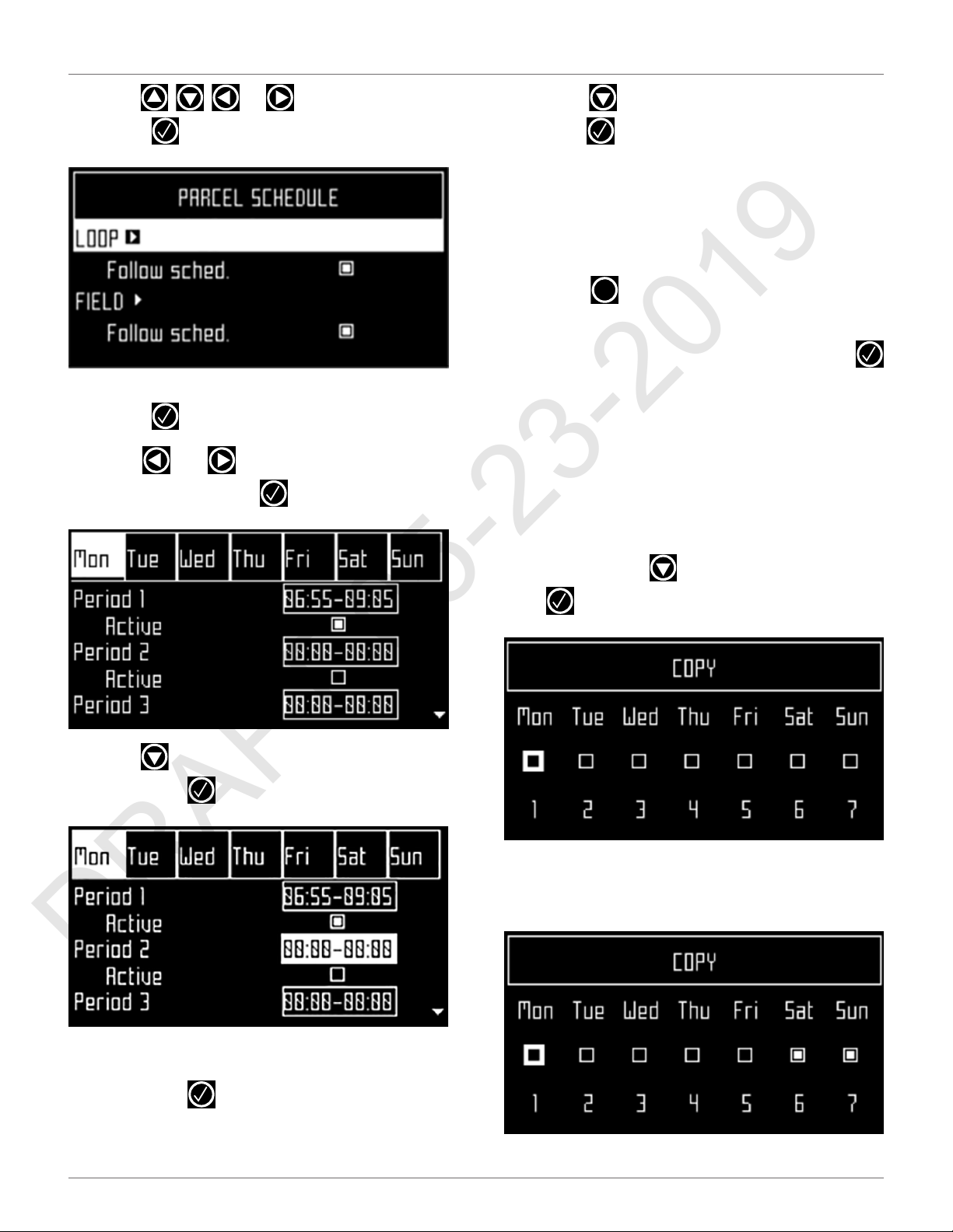
1) Press .
2) Press or to highlight Schedule, then
press . The following screen will appear.
There are two columns for each day because
there are two parcels that have been defined.
This screen shows the current schedule, where
the white blocks represent the time when the
robot will be operating in one parcel. By default,
all the time periods will appear white, meaning
the robot will work continuously.
To execute the operations:
1) Open the STOP button cover.
2) Press .
3) Press or to highlight the required
command, then press .
4) Close the STOP button cover. If the STOP button
cover is not closed within 10 seconds, the operation is canceled and will need to be repeated.
27
Page 32
USING THE ROBOT
DRAFT 05-23-2019
THE SETTINGS MENU
3) Use , , , or to highlight Edit, then
press . The following screen appears:
4) To edit the schedule, highlight the parcel, then
press .
5) Use and to select the required day of
the week, then press .
8) Press to select the active check box, then
press to activate the defined session.
NOTE: In the figure above, Period 1 is active, Period 2 is inactive.
9) Repeat the process for all days and time periods
required. note: The defined schedule can be
copied to another day.
10) Press to return to the “Parcel Schedule”
screen.
11) Use the arrows to select Follow sched. Press
to check the button ON to ensure that the robot
follows the defined schedule. When unchecked,
the robot will ignore the timetable and work
continuously.
To copy the schedule from one day to another:
1) Follow the procedure above to define the
mowing schedule for one day.
2) When all the required periods have been
X
6) Use to select the required period in the day,
then press .
defined, press to highlight Copy, then press
. The following screen will appear:
3) Press the number key that corresponds to the
day to which the schedule is to be copied (more
than one day can be selected).
7) Use the numeric keyboard to enter the start and
end time values where the cursor is flashing,
then press .
28
Page 33
USING THE ROBOT
DRAFT 05-23-2019
THE SETTINGS MENU
4) Press .
5) Highlight Edit.
6) Press .
7) Use the arrow keys to highlight Follow sched.
then press to uncheck the button.
7.4.2 Cutting Heads
The robot is supplied with five cutting heads which,
under normal conditions, should all be used. When
there is a problem with a cutting head, use this menu
to disable it.
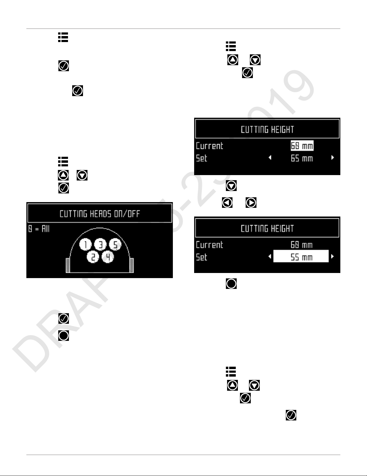
To enable or disable specific cutting heads:
1) Press .
2) Press or to highlight Cutting heads, then
press . The following screen appears:
To set the cutting height:
1) Press .
2) Press or to highlight Cutting height,
then press . The following screen appears,
which shows the current cutting height. NOTE: If
this value is negative, a reset of the parameters
has taken place and the cutting height needs to
be re-calibrated.
3) Press to highlight the Set value.
4) Use and to scroll to the required value.
3) Press the number key(s) that corresponds to the
cutting head(s) to enable or disable it. NOTE:
Press 0 on the numeric keypad to select all
cutting heads.
4) Press .
5) Press to return to the main menu.
To enable a disabled cutting head, repeat the procedure above, selecting the disabled head.
X
7.4.3 Cutting Height
Use this command to set the height of the blades.
• lowest cutting height is 0.8 in. (20.0 mm)
• highest cutting height is 4.7 in. (120.0 mm)
The cutting height is adjusted in 0.20 in. (5.0 mm) increments.
5) Press to return to the main menu.
7.4.4 System Locking
Use this command to lock the use of the robot. The
command is useful if the field area is in use during the
time when the robot is scheduled to be mowing. The
robot will remain locked until the system is unlocked.
NOTE: It is also possible to create PIN code which must
be entered before specific commands can be issued.
To lock the system:
1) Press .
2) Press or to highlight System locking,
then press .
3) Highlight OK, then press . The following
screen will appear. Enter the robot’s PIN code to
access the menu again.
X
29
Page 34

USING THE ROBOT
DRAFT 05-23-2019
SERVICE MENU
To unlock the system:
1) Enter the PIN code, then press . The robot will
wait for a new command to be issued.
7.4.5 LCD Settings
To modify the LCD settings:
1) Press and hold for three seconds. The LCD
Setting screen will appear.
2) Press or to change the contrast.
3) Press or to highlight Temperature Auto
Adj. When this option is checked ON, the LCD
contrast is automatically adjusted according to
3) Use and to scroll to the required time
zone.
4) Press to accept the time zone.
5) Press to exit the menu.
To set the language:
1) Press .
2) Press the arrow keys to highlight Regional
parameters, then press .
3) Press to highlight Language.
X
the ambient temperature. Press to check or
uncheck this option.
4) Press the 9 key to invert the black and white
colors.
5) Press the 0 key to revert to the factory settings.
6) Press to exit the menu.
X
7.5 Service Menu
7.5.1 Regional Parameters
Use this menu to set the robot time zone and the
language.
To set the time zone:
1) Press .
2) Press the arrow keys to highlight Regional
parameters, then press .
4) Press .
5) Use and to highlight the required
language.
6) Press to accept the language.
7) Press to exit the menu.
X
7.5.2 Connections
To display the connections screen:
1) Press .
2) The Connections screen will display. Use the
arrow keypad to select an option.
IP address
Select to display the current IP address of the robot,
depending on the mode on which it is operating.
Modes can be mobile, vpn, or WiFi.
Mode
30
Select to set the mode in which the robot is to operate.
Mode selections are:
Page 35
USING THE ROBOT
DRAFT 05-23-2019
SERVICE MENU
• OFF - The robot will not be connected to a
network.
• Client - The robot will connect to the selected
network as a client.
• Access point - The robot will use its inbuilt
modem to generate its own WiFi network to
which you can connect.
Search for networks
This option appears when the robot is not connected or
cannot detect a WiFi network.
SSID
This displays the name of the WiFi network to which
the robot is connected, and allows you to modify it.
Highlight {network name} and press .
A list of networks will display.
• Entries in bold text are ones that the robot has
connected to.
• Entries in normal text are available but which
have not been used.
• [*] indicates the actual network to which the
robot is connected.
• [!] indicates that the network to which the robot
is connected, is not encrypted using either WPA
or WPA2 technologies. This is therefore an insecure network and the [!] indicates a warning.
• [-] indicates that the network has been disabled.
• To connect to a different known network, high-
To set up the robot as a client:
1) Press .
2) Highlight Connections and press
3) Highlight Mode and set it to Client. If the robot
has not been connected to a WiFi network,
selecting the option Search for networks will
search for networks and present a list of those
available.
4) Highlight the WiFi network required and press
.
5) Enter the password for the network using the
keyboard.
6) Highlight V and press .
7.5.4 Operations
Use this menu to set the following operating parameters:
Min temp
Sets the lowest operating temperature for the robot.
The default value is 41.0 °F (5.0 °C).
Edit parcels percentage
Use this option to view and modify the assigned to each
of the parcels that have been defined. The percentage
value assigned to a parcel determines the proportion of
times the robot will start mowing in the parcel.
light the network, press and select Enable
Network.
• To modify the current network, highlight the
network, press . The following operations are
available:
– Disable Network - Disconnects the
robot from this network.
– Change Password - Allows modification
of the password to access the network
from the robot.
– Forget Network - Removes the recogni-
tion of this known network from the
robot.
To set the operating parameters:
1) Press .
2) Use the arrow keys to highlight Operations, then
press .
3) Press or to highlight the required
parameter.
4) Enter the required value.
5) Check that the current values have been
updated.
6) Press to return to the main menu.
X
7.5.3 Using the Robot as a Client
For normal operation, set up the robot as a WiFi client.
This will enable the robot to communicate with the
portal on the web-server.
31
Page 36

USING THE ROBOT
DRAFT 05-23-2019
SERVICE MENU
7.5.5 Device
Use this menu to display the characteristics of the
device and change the robot’s name.
By default the name of the robot corresponds to the
serial number.
To change the name of the robot:
1) Press .
2) Press the arrow keys to highlight Device info,
then press .
Serial number
Serial number of the robot.
Latitude
Current latitude of the robot position.
Longitude
Current longitude of the robot position.
Visible satellites
Number of satellites that the device can currently
detect.
Lat [GF center]
The current latitude of the center of the Geofence
security zone.
Long [GF center]
The current longitude of the center of the Geofence
security zone.
Radius
Current radius of the Geofence security zone.
3) Highlight Robot name and press .
4) Highlight the back arrow to delete the current
name.
5) Use the alpha-numeric keyboard to enter the
new name. Highlight each character required
and press to select it.
6) Highlight V in the bottom row and press .
7) Press to accept the new name.
8) Press to return to the main menu.
X
7.5.6 Device info
To see the device info:
1) Press .
2) Press the arrow keys to highlight Device then
press .
3) Highlight Device info and press .
4) Press or to scroll through the list.
Dist. to beacon
This option is not used in North America.
DW board not installed
This option is not used in North America.
Magnetic distance
The distance between the robot and the peripheral
wire.
This value should be positive when the robot is inside
the peripheral wire loop. If the distance is shown as a
negative value, it is necessary to reverse the phase. See
Infrastructure > Peripheral wires > WireCH# from the
technician’s menu.
MAC address
MAC address.
7.5.7 System version
To see the System version information:
• Press .
• Press the arrow keys to highlight Device, then
press .
• Highlight System version, then press .
Robot name
The name of the robot.
• Press or to scroll through the list.
32
Page 37
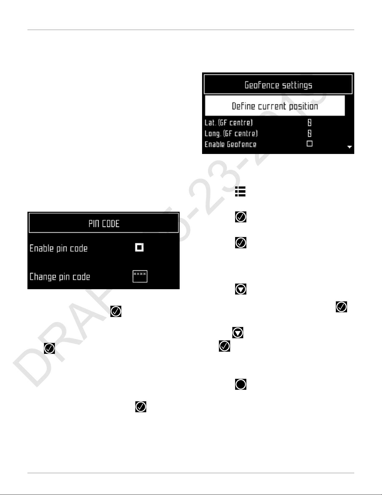
USING THE ROBOT
DRAFT 05-23-2019
SERVICE MENU
Version
Current software version.
Brain version
Current AI version.
System version
Current version of the system software.
Software version
Current version of the application software.
Bootloader ver.
Current bootloader version.
7.5.8 Security
Use this menu to enable or disable the use of a PIN
code and to define a security area in which the robot is
allowed to operate.
NOTE: By default the pin code is 0000. To obtain the Pin
Code menu, enter 0000.
this area, a security notification will be issued. The
circular area is defined by its center and a radius.
The current location of the center point can be viewed
in the device settings menu.
To define and implement a security zone:
1) Move the robot to the required center of the
security zone.
2) Press .
3) Press the arrow keys to highlight Security, then
Enable pin code
Highlight the check box. Press to toggle the setting.
Enable PIN code OFF
Enable PIN code ON
Press to accept the new setting.
From now on certain commands will require the PIN
code to be entered before they can be executed.
Change pin code
Use to change the pin code.
press .
4) Press the arrow keys to highlight Geofence and
press .
5) Highlight Define current position. The latitude
and longitude of the current position is
displayed.
6) Press to highlight Enable Geofence.
7) Make sure this option is checked on. Press to
toggle the setting.
8) Use to highlight Radius value, then press
.
9) Use the numeric keypad to enter the required
value.
10) Press to return to the main menu.
X
Enter the required numbers and press .
7.5.9 Geofence
This option is not available in North America.
A Geofence is a circular security zone in which the
robot is allowed to operate. If the robot moves out of
33
Page 38
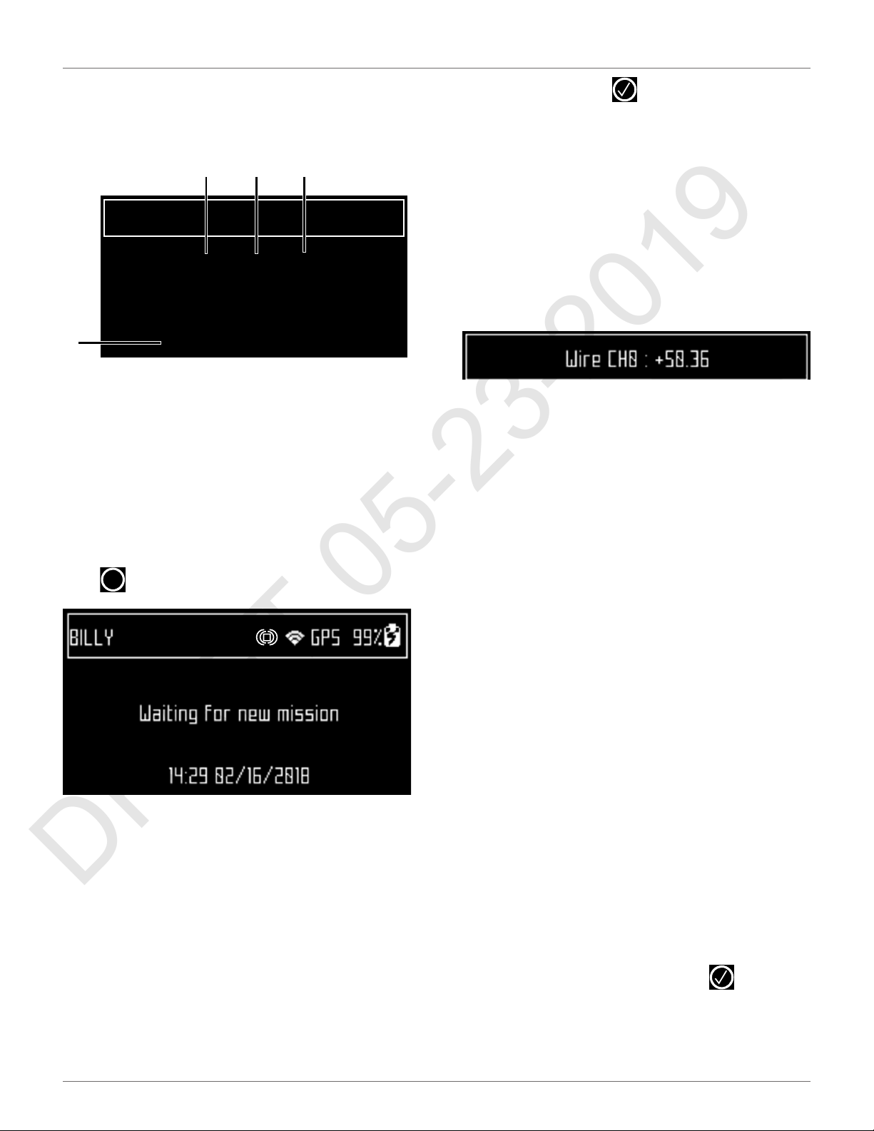
USING THE ROBOT
DRAFT 05-23-2019
ADVANCED PARAMETERS
7.6 Advanced Parameters
Press and hold 0 on the numeric keypad until the
ADVANCED PARAMETERS screen appears.
1
ADVANCED PARAMETERS
Wire CH1: -11.29 Good shape
Wire CH0: +511.75 Bad shape
Wire CH2: -13.87 Good shape
4
1 – Wire channel numbers (Wire CH#). This is a list of currently
defined peripheral wires.
2 – Distance the robot is from the peripheral wire. - A positive
value indicates the robot is inside the peripheral wire. A negative
value indicates the robot is outside of the peripheral wire.
3 – Wire integrity - “Good shape” indicates a good wire
connection. “Bad shape” indicates the wire is damaged or not
connected properly.
4 – GPS position (longitude and latitude).
GPS position : 50.736893 / 4.586355
2 3
Select a wire and press to see the wire properties.
Create new wire
Use to Create a new wire.
Wire CH#
Wire id and magnetic distance
The identification of the wire in terms of the associated
channel is displayed. In addition the current value and
sign of the magnetic distance between the robot and
the wire is indicated.
Signal channel
The signal (frequency) channel for the peripheral wire.
This corresponds to the channel set using the rotating
switch in the charging station. In the case of a
multi-field installation, each wire used, must be
assigned to a specific channel.
7.7 Technician's Menu
Reverse phase
The sign of the phase on the inside of the field is oppo-
Press repeatedly until the home screen appears.
From the Home screen, press and hold 9 on the
numeric keypad until the TECHNICIAN SETTINGS
screen appears.
X
7.7.1 Infrastructure
Use the operations in this menu to configure the
robot's installation in the field.
Peripheral wires
Use to configure the "Wires Setting" screen.
Wire CH#
A list of defined wires is presented, with the corresponding channel number. The list of parcels associated with the wire is listed below it.
site to that on the outside. This is how the robot can
detect whether it has crossed the peripheral wire. The
phase should be positive inside the field.
To determine if this is the case, examine the magnetic
distance value shown at the top of the screen. If the
value is positive the phase is correct. If it is negative,
check this option to reverse the phase.
Delete Wire CH#
This option only appears if there is more than one wire
defined. It allows the current wire to be deleted. NOTE:
At least one wire must be defined.
Create New Wire
1) Select Infrastructure > Peripheral wires > Create
new wire.
2) Select OK to confirm that you want to create the
new wire.
3) The new wire and its associated parcel will
appear in the wire settings list.
4) Select the new wire and click on .
5) Select the required channel number. Station
Loop is always channel 0. Field 1 is always
channel 1. Field 2 is always channel 2
34
Page 39
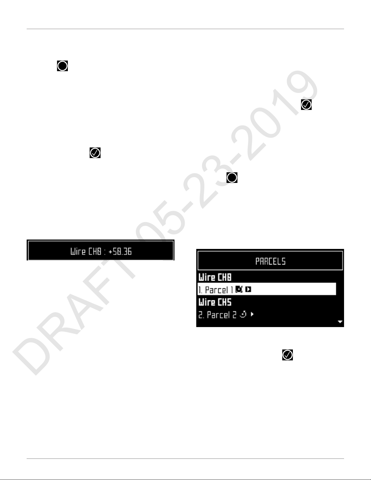
USING THE ROBOT
DRAFT 05-23-2019
TECHNICIAN'S MENU
6) Check the sign of the magnetic distance
displayed at the top of the screen. If this value is
negative, check the Reverse phase button ON.
7) Click to exit the menu.
The newly created wire will appear in the Wire settings
screen.
X
Peripheral Wires
Wire CH#
A list of defined wires is presented, with the corresponding channel number. The list of parcels associated with the wire is listed below it.
Select a wire and press to see the Wire properties.
Create new wire
Use to Create a new wire.
Wire id and magnetic distance
The identification of the wire in terms of the associated
channel is displayed. In addition the current value and
sign of the magnetic distance between the robot and
the wire is indicated.
Create a New Wire
1) Select Infrastructure > Peripheral wires > Create
new wire.
2) Select OK to confirm that you want to create the
new wire.
3) The new wire and its associated parcel will
appear in the wire settings list.
4) Select the new wire and click on .
5) Select the required channel number. Station
Loop is always channel 0. Field 1 is always
channel 1. Field 2 is always channel 2
6) Check the sign of the magnetic distance
displayed at the top of the screen. If this value is
negative, check the Reverse phase button ON.
7) Click to exit the menu.
The newly created wire will appear in the Wire settings
screen.
X
7.7.2 Parcels
The Parcels menu lists the defined channels and their
associated parcels. There is, by default, one parcel
associated with each wire.
Signal channel
The signal (frequency) channel for the peripheral wire.
This corresponds to the channel set using the rotating
switch in the charging station. In the case of a
multi-field installation, each wire used, must be
assigned to a specific channel.
Reverse phase
The sign of the phase on the inside of the field is opposite to that on the outside. This is how the robot can
detect whether it has crossed the peripheral wire. The
phase should be positive inside the field.
To determine if this is the case, examine the magnetic
distance value shown at the top of the screen. If the
value is positive the phase is correct. If it is negative,
check this option to reverse the phase.
Delete Wire CH#
This option only appears if there is more than one wire
defined. It allows the current wire to be deleted. NOTE:
At least one wire must be defined.
For each parcel, the name and indication of the return
direction is shown.
Selecting a parcel and pressing displays the list of
parcel properties given below.
Parcel properties
Name
The current name of the parcel. The name can be
edited.
Return direction
Defines the default direction (clockwise or counterclockwise) in which the robot returns to its charging
station following the wire.
35
Page 40
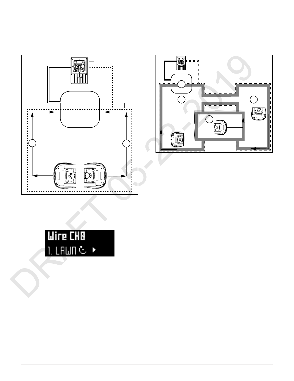
USING THE ROBOT
DRAFT 05-23-2019
TECHNICIAN'S MENU
Set the value of this parameter to ensure that the robot
can return to the charging station in the most efficient
manner. This is important if a problem has occurred
and the robot does not know which parcel it is in.
1
3
2
2
1
The following figure illustrates the advantage of setting
different return directions in different parcels to facilitate the most efficient way for the robot to return to
the charging station.
1
2
3
1 – Parcel 1 (area inside station loop wire)
2 – Parcel 2
3 – Parcel 3
2
1 – Counterclockwise return direction
2 – Clockwise return direction
The current return direction is indicated in the list of
parcels.
Use trackborder
This parameter defines whether the robot uses the
trackborder when leaving or returning to the charging
station.
NOTE: This parameter value must be checked ON in all
parcels which are not the station loop.
This parameter can be checked OFF for the station loop
Trackbord. Min. / Trackbord. Max.
The minimum and maximum values allowed for the
trackborder. The robot will select a random value
between the defined values.
The default minimum value for Trackbord Min.is 2.6 ft.
(0.8 m). The default maximum value for Trackbord.
Max. is 9.8 ft. (3 m).
36
Page 41
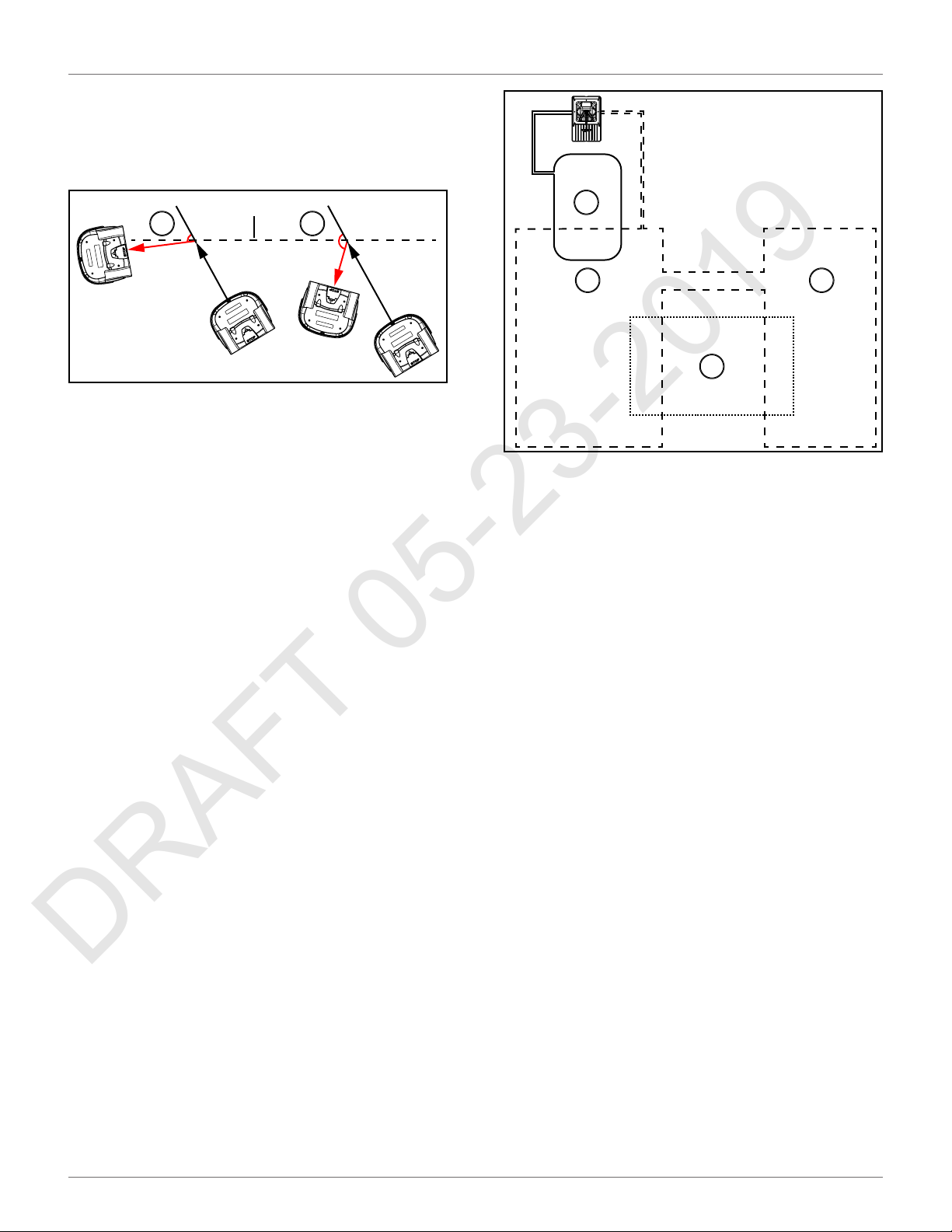
Min. Bounce Angle / Max. Bounce Angle
DRAFT 05-23-2019
This is the angle through which the robot turns when it
arrives at the peripheral wire. The range of values for
this parameter is typically between 60° and 120°.
USING THE ROBOT
TECHNICIAN'S MENU
1
3 2
1 – Peripheral wire
2 – Min. Bounce Angle
3 – Max. Bounce Angle
Perimeter
This defines a distance the robot will travel along the
trackborder to return to the charging station. If the
robot travels the distance defined by this parameter
and does not find the station, it will issue an alarm.
The recommended value of this parameter is the
length of the peripheral wire around the field to be
mowed, the default value is 1000 m.
Neighboring parcels
It is necessary to define how parcels are located relative to each other so that the robot can determine the
route required to reach a particular parcel. Two parcels
are considered neighbors if they overlap. In the
following figure:
• Parcel 1 is a neighbor of Parcel 3
• Parcel 3 is a neighbor of Parcel 2
1
2
3
1 – Parcel 1 (area inside station loop wire)
2 – Parcel 2
3 – Parcel 3
In the example above, select Parcel C and then check
the buttons next to Parcel A and Parcel B.
StartZones
This menu displays a list of the defined start zones and
enables you to create a new one. Start zones define
where the robot will start mowing after it has left the
station.
2
7.7.3 Stations
The "Paired Stations" screen appears.
Existing stations
If stations have already been defined a list of them is
presented.
Selecting a station enables you to view and edit the
properties of the station. These are the same as those
used in creating the station.
Create manual station
Allows you to manually create a new station.
This procedure is required to define a station that does
not use a positioning beacon.
Create new station
The charging station must be defined manually. Define
the following parameters.
37
Page 42

USING THE ROBOT
DRAFT 05-23-2019
TECHNICIAN'S MENU
Charge
This defines whether the charging station is used to
charge the robot or not.
Connected to parcels
This defines which of the defined parcels the station is
connected to. For a multi-field installation a list of
defined parcels will be presented and button next to
the required one must be checked ON.
NOTE: This parameter must be defined for a multi-field
installation.
Station Inside Parcel's Wire
This specifies whether the station is located inside or
outside of the peripheral wire.
If the station is inside the wire, check the button ON.
Delete
Use to remove the manually created station from the
installation.
Station Properties
Station properties include details of a station. This
menu also allows you to specify Access parameters,
which determine how the robot will enter and leave
the station, and Start Zones, which are the points at
which the robot start mowing after leaving the station.
where the robot will start mowing after it has left the
station.
NOTE: A start zone defined here is only used for a
installation that contains a single wire and a positioning
beacon.
7.7.4 Mobile Connection
In the absence of a wireless network, the robot
contains a SIM card that enables you to use 4G technology in the field.
Select the Mobile connection in the list and press .
Mobile Connection Options
Status
Displays the current mobile network status.
Network
Displays the name of the current network operator.
Network Carrier
Displays the name of the current network carrier.
APN
Displays the current id of the Access Point Name of the
SIM card.
Charge
Defines whether the station is used to charge the robot
or not.
Software version
The current version of the software for the station.
Connected to parcels
This defines to which of the defined parcels the station
is connected. For a multi-field installation a list of
defined parcels will be presented and button next to
the required one must be checked ON.
NOTE: This parameter must be defined for a multi-field
installation.
Station inside Parcel's wire
This specifies whether the station is located inside or
outside of the peripheral wire loop.
If the station is inside the loop, check the button ON.
Start Zones
This menu displays a list of the defined start zones and
enables you to create a new one. Start zones define
Radio
3G/2G/UMTS/4G.
Signal Strength
Signal strength in dB.
Bit Error Rate
Number of errors during transmission. Very standard in
every communication.
ICCID
Integrated circuit card identifier.
IMEI
International Mobile Equipment Identity.
IMSI
International Mobile Subscriber Identity
PLMN
Public land mobile network.
38
Page 43

USING THE ROBOT
DRAFT 05-23-2019
TECHNICIAN'S MENU
MCC
Mobile Country Code. This code identifies the country.
For example, in China MCC is equal to 460, in USA - 310,
Hungary - 216, Belorussia - 257.
MNC
Mobile Network Code. This code identifies the mobile
operator.
LAC
Location Area Code.
Cell ID
A unique number used to identify each Base transceiver station (BTS) or sector of a BTS within a Location
area code.
7.7.5 Demonstration
Check the option ON. Confirm you want to ignore the
peripheral wire.
Use this mode to demonstrate the performance of the
robot before installation of the peripheral wire.
Cutting height
The cutting height values need to be calibrated if
• erroneous values (negative) values are displayed
• a cutting head has been replaced
• the belt lifting the cutting heads has been modified or replaced
During the calibration procedure the cutting heads are
lifted until they reach their maximum height. Their
position during this movement is termed the "raw position" and when the maximum height is reached, it is
termed the "homing position" and assigned a scalar
value. When the homing position has been reached,
the cutting heads can be lowered to the required
height.
1) To calibrate the cutting height, press to
select Calibrate now,then press .
2) The robot will move the cutting heads up to the
maximum height. The cutting heads will then be
lowered to the required height.
3) When the value is OK, set the required cutting
height.
OPERATIONAL HAZARD
The robot will ignore the electromagnetic field generated by the peripheral wire when operating in
demonstration mode.
• Do not leave the robot unsupervised when it is
operating in demonstration mode.
7.7.6 Service
Cutting heads
Use this option to calibrate the rotational speed of the
cutting heads.
1) If a cutting head has been modified, or if a new
cutting head has been installed, press to
select Calibrate now, then press .
2) Close the lid.
3) The cutting heads will be rotated and the rotational speed evaluated.
4) When an audible beep is heard, open the lid and
view the results.
5) If any of the heads display a NOK value that is not
in line with the others, examine the heads and
see if there is any sort of blockage that is
preventing the head from rotating normally.
4) If there is a problem, examine the cutting heads
and see if there is anything blocking the movement over the complete range.
Information
Total distance
This is the total distance (in meters) traveled by the
robot to date. Use this information to decide when
maintenance is required.
Bumper resistance
Displays the current value of the bumper resistance.
This should lie in the range 82-94 kΩ.
Tests
These tests are only to be run by an authorized ECHO
Robotics Technician.
Use this menu to execute tests on a number of components. These tests will be carried out before the robot
is delivered to a customer and at the end of a regular
service.
To execute a test:
1) Press to select the test(s) you want to
execute.
2) Press to select the test.
39
Page 44

USING THE ROBOT
DRAFT 05-23-2019
TECHNICIAN'S MENU
3) Repeat this for all tests required.
4) Select Start and press .
5) The robot will start executing each of the
selected tests. Follow the instructions given on
the screen.
Charge Test
This test checks if the:
• robot can detect a charge
• received charging current is sufficient
When this option is selected, the following information
is displayed:
X/Y CHARGE _LR
X represents the current test in the current sequence.
Y represents the total number of tests to be performed
in the current sequence.
Charge_LR is the name of the current test.
Detect
This displays whether the robot can detect a voltage on
the left and right sides.
KO means it can not detect a voltage on the left or right
side. OK means that it can detect a voltage.
Current
This displays whether a sufficient charge current can be
detected (>7A).
KO means it can not detect sufficient charge current on
the left or right side. OK means that it can detect sufficient charge current.
[value]
The current on the connected side.
Discharge required for current test
You will see this message if the current battery level is
above 95%. It is best to perform this test when the
battery charge level is lower.
To test the charge:
1) Connect one side of the robot to the charging
station.
2) The result will be displayed.
3) Repeat this for the other side.
If the results of the test are KO, check the connections
between the robot and the charge station arms.
Bumper
This test checks that the electrical resistance of the
bumper is within the correct range and that it responds
to pressure from an obstacle.
The following information is shown.
X/Y BUMPER SENSORS
X represents the current test in the current sequence.
Y represents the total number of tests to be performed
in the current sequence.
BUMPER SENSORS is the name of the current test.
Activate sensors
The sides of the bumper that need to be tested by activating. (Bumper Left Bumper Right)
Disable Sensors
The sides of the bumper that need to be disabled
(Bumper Left Bumper Right)
To test the Bumper
1) Check that Bumper Left Bumper Right are listed
below Activate sensors.
2) If these are listed under Disable Sensors, remove
any constrictions that are compressing the
bumper.
3) Press your hand against the right or left side of
the bumper.
4) If the resistance is modified sufficiently the item
will be remove from the list.
5) Repeat this process on the other side of the
bumper.
6) If an item remains in the list, the bumper is not
functioning correctly and needs to be replaced.
Smartbox
This test checks all the functionality of the user interface panel.
To test the Smartbox
1) Follow each of the instructions as they appear on
the screen.
2) Press to answer Yes to a question and to
answer No.
3) If the item being tested is operating correctly it
will disappear from the list.
If there is a problem with any of the items, replace the
Smartbox.
X
40
Page 45

USING THE ROBOT
DRAFT 05-23-2019
TECHNICIAN'S MENU
Lift Sensors
This checks whether each of the lift sensors is
responding correctly.
X/Y LIFT_SENSORS
X represents the current test in the current sequence.
Y represents the total number of tests to be performed
in the current sequence.
LIFT_SENSORS is the name of the current test.
Activate sensors
The lift sensors that need to be tested by activating by
lifting (Lift1, Lift2, Lift3, Lift4).
Disable Sensors
The lift sensors that need to be disabled by depressing
them (Lift1, Lift2, Lift3, Lift4).
To test the Lift Sensors
1) Check which Lift sensors are listed below Activate sensors.
2) Lift each of sensors in turn.
Disable Sensors
The number of sensors that need to be deactivated
(CollisionLeft, CollisionRight).
To test the Back Sensors
1) Check that CollisionLeft and CollisionRight are
listed below Activate sensors.
2) If these are listed under Disable Sensors, remove
any constrictions activating them.
3) Push the body of the robot backwards on one
side so that it moves relative to the chassis.
4) If the backward sensor on this side is functioning
correctly it will be removed from the list.
5) Repeat this on the other side.
6) If an item remains in the list, the backward
sensor is not functioning correctly. Visually
inspect it to see if there is a constriction that is
impeding its function. If not, replace it if necessary.
Signal Sensors
3) If the lift sensor is operating correctly, the item
will be remove from the list.
4) Repeat for the remaining lift sensors.
5) If there are sensors listed under Disable Sensors,
push down on the lift sensor to deactivate it.
6) When all the items have been removed from the
list the test is complete.
7) Any items that remain in the list are not functioning correctly and need to be replaced.
Backwards Sensors
This checks that the backwards sensors are operating
correctly.
The following information is shown.
X/Y BACK_SENSORS
X represents the current test in the current sequence.
Y represents the total number of tests to be performed
in the current sequence.
BACK_SENSORS is the name of the current test.
Activate sensors
This checks the functionality of the coil that is used to
detect a signal on a peripheral wire.
The following information is shown.
X/Y COIL0_CENTER
X represents the current test in the current sequence.
Y represents the total number of tests to be performed
in the current sequence.
COIL0_CENTER is the name of the current test.
Detecting wire < {value}
{value} is the value of the "track value". If the result of
the test is less than this value, the test is successful.
CH{A}:{result value}
If the test result is greater than the defined "track
value", it will be listed here.
Move the robot closer to the signal wire detected.
When the value is less than the "track value", the item
should be removed from the list.
If the robot is close to the wire and the displayed values
are high (900 or more) it is an indication that the coil
connections are not good.
The number of sensors that need to be tested by activating them (CollisionLeft, CollisionRight).
Drive Motor
This checks the function of the drive motor. It checks
that:
41
Page 46

USING THE ROBOT
DRAFT 05-23-2019
ERROR MESSAGES
• the motor drives the wheel forward at 0.2 mph
(0.1m/s)
• a current of 2.5 A is delivered to the motor
To test the Drive Motor
1) Press to start the test.
2) Close the lid when requested.
3) The robot will move forward a short distance
then stop and beep.
4) Open the lid.
5) If the robot moved forward, answer Yes to the
question by clicking .
6) If the robot moved backwards answer No to the
question by clicking . If this is the case,
reverse the connections on the drive motor
cable.
If the robot did not move, or only one wheel moved,
the test will fail, and the report will indicate the
problem.
1) Visually inspect the drive motors to see if there is
a blockage.
2) Check the fuse and the cabling for the drive
motors.
Cutting Motor
This test rotates each of the cutting heads and verifies
that their rotational speed is correct.
If any of the heads display a NOK value that is not in line
with the others, you will need to examine those heads
and see if there is any sort of blockage that is
preventing it from rotating normally.
X
functioning correctly and there is some precision in
their positioning.
Software update
This menu enables you to perform a software update.
The current software version is displayed.
Select Update now, then press . The robot will
contact the server, download and then install the latest
software version.
7.7.7 Advanced Parameters
Max speed
Use this menu to set the maximum speed at which the
robot will to move. The maximum speed is 2.2 mph (1.0
m/s). This is also the default speed setting for the
robot.
Wire crossing distance
Use this menu to set the distance the robot will move
when it crosses the peripheral wire, before turning
back into the field again.
The default value is 8.0 in. (0.2 m). This distance
represents the distance between the front of the robot
and the position of the coil that detects the presence of
the wire.
NOTE: The values of distances between the peripheral
wire and boundary of the area to be mowed are based
on the use of a wire crossing distance of 8.0 in. (0.2 m).
Min temp
Sets the lowest temperature at which the robot will
operate. The default value is 41.0 ° F (5.0 °C).
NOTE: Mowing at too low a temperature can damage
the grass.
Sonars System
This performs a test to verify that the sonar sensors are
operating correctly.
If any of the sonar sensors are found to be defective,
they need to be replaced. An indication of which sensor
needs to be replaced is given.
Lid
In order for the robot to be able to execute its missions
the lid needs to be shut, and to form a closed circuit
between magnets on the lid and relays on the body.
This circuit needs to be open when the lid is open and
when the lid is pressed down and acts as the stop
button. This requires that all magnets and relays are
7.8 Error Messages
Report error messages to your authorized ECHO
Robotics Dealer. Always note the date, time, and robot
serial number.
Error Message Description
Battery temperature
issue
Battery over voltage
Bad battery connection
Battery temperature is
above or below the
allowed limit.
One, or more, battery
cell voltage is over the
limit.
Internal problem with
the battery.
42
Page 47

USING THE ROBOT
DRAFT 05-23-2019
ERROR MESSAGES
Error Message Description
Values displayed for the
battery on the GUI
Bad battery measure
BMS communication
wire is not connected
Shutdown in 2 min /
inhibit shutdown
principal / unblock
brakes
Some wires not well
configured. Please add at
least one parcel to each
wire
No charge current; Check
contacts and charging
station
The robot has no wire to
mow. Please configure at
least one wire.
The robot has no parcel
to mow. Please configure
least one parcel.
No peripheral signal!
screen do not
correspond to the actual
values.
BMS (Battery
Management System)
wire is not connected
properly. This refers to
the electronic part of the
battery.
GUI (Graphical User
Interface) screen
displays the alarm- and
asks if you want to
inhibit the shutdown.
The LED is blinking very
fast (~5x per second).
The brakes are
deactivated.
Battery charge level is
critically low.
Configuration of wires
and parcels is incorrect.
At least one wire must
be defined in the
installation
configuration, and at
least one parcel must be
assigned to each wire.
Charging station voltage
is detected but there is
no supply current.
No wire has been
configured.
No parcel has been
configured. At least one
wire must be configured
defining a field to mow,
and a parcel must be
defined for each wire.
Robot is unable to detect
a valid magnetic signal.
Error Message Description
Robot has reached the
charging station and
started to charge, but at
Station contact lost for
{0}s!
Wrong wire and parcels
Configuration
No station contact
detected
Wire Lost during
TrackWire!
Unlock system: bad pin
code
Unable to find the
working area
Failed to dock to station
Head {0} is blocked!
Head {0} did not start!
a certain time the
charging station contact
is lost. If the contact loss
lasts for more than one
hour, this alarm is
triggered.
Robot has encountered a
problem while mowing
in a particular parcel.
When the robot re-starts
it is not sure in which
parcel it is located, and
where it should start
mowing.
The robot has executed
the loopstep, but has not
made contact with the
charge arms after 29 m
(by default).
Robot is following the
trackwire and is then
unable to detect a signal
on the wire. When this
happens the robot will
rotate 360° in an
attempt to detect a
phase difference, and
then issue this message.
"System blocking" is set
and must be unblocked
by entering a pin code.
An incorrect code has
been entered.
The robot is unable to
find a valid magnetic
signal.
Robot has tried to return
to the charging station
but failed.
Occurs when a cutting
head should be spinning,
but is not
Cutting head should be
spinning but it does not
start.
A command to change
Motor blocked when
going {0} to {1}mm
There is no 12V
peripheral for {0}
the cutting height has
been issued, but the
cutting head can not
move.
12 V power supply does
not work properly.
43
Page 48
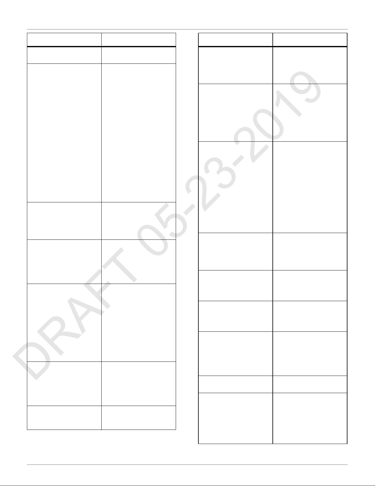
USING THE ROBOT
DRAFT 05-23-2019
ERROR MESSAGES
Error Message Description
There is no 5V for {0}.
STOP button issue
detected
Unexpected exit zone
event
The {L/R} fuse is blown
or the {L/R} motor is not
connected
Failed to consistently
re-enter the zone
SelfTest failed to clear
within 15s
Unhandled exit zone!
5 V power supply does
not work properly.
Stop button is not
operating correctly. The
Stop button lid must be
closed when the robot is
operating.
The Stop button lid is
determined to be closed
by detecting a closed
circuit between magnets
on the lid and relays in
the body. If these
magnets are and relays
are not connecting
correctly the correct
state of the lid can not
be determined. This can
arise due to wide
temperature
fluctuations.
Robot did not exit from
the charging station
correctly, possibly
turning in the wrong
direction.
Robot can not detect any
current in either the left
or the right wheel motor.
Either a fuse or a
connection is faulty.
Robot has crossed the
peripheral wire, but is
not able to re-enter the
field where it is mowing.
Possible reasons are a
loss of signal or the robot
is physically unable to
re-enter the field
because of mud or
obstacles.
When the robot starts
up, it executes a self-test
of a range of functions.
This error occurs if a
failure occurred on any
of the functions tested.
A problem arises as the
robot exits the charging
station.
Error Message Description
Robot is in the charging
Waiting for station
contact
Wait for 5 Seconds of full
contact
Waiting for signal
Noise on bumper
Lift(X) Detected Front/Rear Left/Right
Too many repetitive
collisions!
Unhandled collision
event!
Sonars issue detected
Collisions at start-up: {0}
station and it loses
contact. It will wait one
hour before generating
the alarm.
Contact with the
charging station arm has
been lost.
There is insufficient
voltage on the charging
station arm to charge the
robot.
The signal on the
peripheral wire is lost.
The robot will wait for a
period of 12 hours and
then start again - if the
signal has been restored.
This message appears if
the Stop button lid is
opened during the 12
hour period.
There is no signal on the
peripheral wire.
Electrical (background)
noise level on the
bumper is high enough
to impair the proper
operation
A cover lift is detected.
An obstacle has caused
the cover to be lifted.
A series of repetitive
collisions is detected.
Too many obstacles.
Robot has detected small
obstacles in the mowing
field, which are not large
enough to trigger the
operation of the lift
sensors.
One of the sonar sensors
is malfunctioning.
The robot can not
resolve a collision at
start up.
There is an obstacle
blocking the robot start
up.
44
Page 49
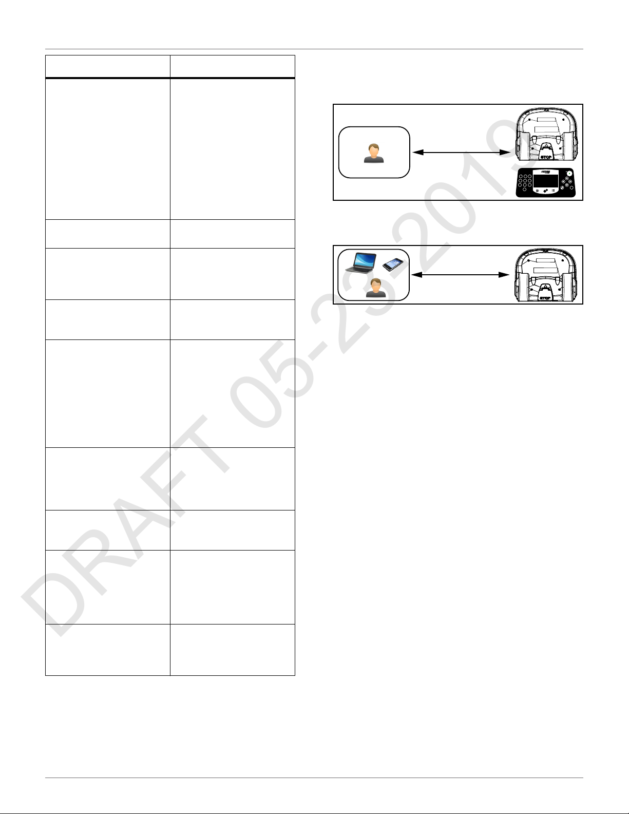
USING THE ROBOT
DRAFT 05-23-2019
CONNECTING TO ROBOTS
Error Message Description
The robot is leaving the
charging station. The
robot encountered an
obstacle (at {X} meters
from the charging
Collision too close to
station ({X}m)
DMA Error, on sonars:
{0}
LongCollision ({0}) event
detected
Still in collision
({0})!alarm
Wait for no collision
Did not find the zone due
to collision ({0})
ManualTask shall not
complete: MotorDrive is
in safety.
The wire is currently
configured to be
ignored.
Cannot start MotorMow
If we are in
Alarm/Safety. Check
navigation.
station), but was unable
to move around it
because it was too close
to the charge arms.
Obstacle too close to the
charging station.
A hardware error in the
sonar control system.
either a lift or a
backwards sensor has
been blocked for at least
10 seconds.
A maneuver to avoid a
collision has failed after
one minute.
Occurs after a collision.
The robot moves
backwards and then
checks if the obstacle is
still there. It will then
wait until the obstacle
has been removed. This
message appears while it
is waiting.
Robot has crossed the
peripheral wire, but was
unable to re-enter the
zone to be mowed
because of an obstacle.
Robot did not start.
Robot sends a cautionary
message before starting
work. It can come out of
its area and there is a
risk it could fall into
water
Robot was asked to
start, but an existing
alarm has not been
cleared.
7.9 Connecting to Robots
Communication with a robot is available through:
• Direct interaction with the robot. This type of
communication refers to the direct operation of
the robot using the user interface. There are
some instructions which can only be issued using
this method of communication.
31 2
6
4 5
8
7 9
0
• Direct access using a smartphone, tablet, or
personal computer.
• Remote access via the web server. This method
of communication allows a user to connect to the
robot using a smartphone, tablet, or personal
computer, via a web server using the internet.
• A user account is required to access the web
server. This depends on the concepts of Entities,
Users and Roles, and Robots.
Through access to the web server the user can:
• Receive notifications about problems encountered by the robot (alarms and warnings).
• Issue commands to remotely control the robot,
such as send to station, start from station, etc.
• Change or remotely configure some parameters,
such as the working hour.
• Monitor the performance of the robot.
• Implement automatic software updates.
X
7.9.1 Entities, Users and Roles, Robots
Entities
An entity is a group of users and robots associated with
a "site". Each entity can have a number of robots that
are used within the site.
There are five entities in the image below that are
related in a hierarchical structure. The parent entity is
the "City Authority". It has four child entities:
• Sports Field 1
• Sports Field 2
• Park West
• Park East
45
Page 50
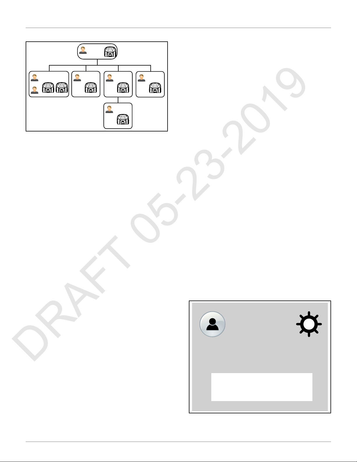
USING THE ROBOT
DRAFT 05-23-2019
CONNECTING TO ROBOTS
The entity "Park West" has a child entity "Golf Course".
City Authority
User A
User B
User C
Sports Field 1
User D
Sports Field 2
User E
User F
Park West
Golf Course
User G
Park East
User Roles
A user has an account that is associated with an entity.
This is referred to as the user's "home" entity. The
information and the operations available to a user
depend on the roles that are have been assigned to the
user. The following roles are available.
Standard User
A user with this role can view and follow the robots but
has no control over them.
RobotControl
A user with this role can send commands from the
portal or from the application, and change schedules
on line.
EntityManager
A user with this role can create or delete other users or
sub-entities as part of its hierarchy. The user can also
move robots between sub-entities.
Technician
7.9.2 Accessing the Web Server
NOTE: Before you can access the web server you need
to have set up an account. See Creating Accounts.
The web server can be accessed using a web browser,
on a personal computer, or by using the application
that can be downloaded onto a smart phone or tablet.
NOTE: This section refers to the use of the web-server
through a browser.
To access the web server:
1) Enter the URL https://myrobot.echorobotics.com in the browser.
2) Enter the email address used to activate the
account.
3) Enter the password defined when you activated
the account.
4) Click [Login].
You can then:
• Modify your profile parameters.
• Change your password.
• See a list of your robots and information about
their activity, alarms, statistics and the map of
the field they mow.
• Create and manage users and entities. This functionality is only available to users who have a
suitable role.
• Specify the type of notifications you want to
receive and how they will be delivered.
• Access documentation.
To Modify Your Profile
1) Click on the gear wheel next to your user name.
A user with this role can see and read more details on
the robot versions. The capabilities of this user will be
progressively increased with access to technical data
Your Name Here
not available to end users.
Robots
Robots are transferred from a parent entity to a child
entity when the robot is "sold" by the parent to its
child. The end-user entity and the end-user account
used to access the web server are created at the
moment when the robot is commissioned. Following
this, the account holder will receive an email from
which the account can be activated.
In the case where an end-user purchases a robot
directly, an account will be created using the informa-
2) Click on Profile.
tion received on the registration card supplied with the
robot.
3) Modify any of the settings.
Profile
Log out
46
Page 51
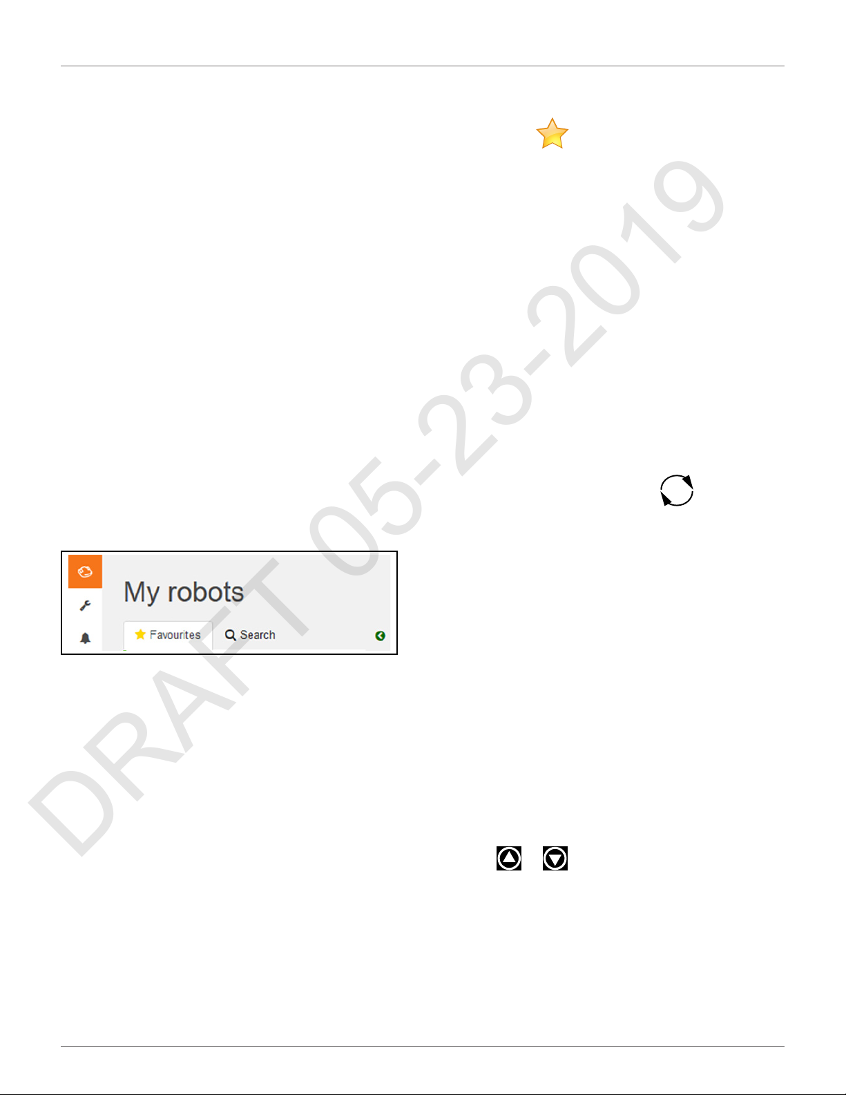
USING THE ROBOT
DRAFT 05-23-2019
CONNECTING TO ROBOTS
4) Click [Register].
To Change Your Password
The password was set when you activated the account.
1) Click on the gear wheel next to your user name.
2) Click on Profile.
3) Scroll down to the Password panel.
4) Enter your current password. (If you have
forgotten the password, click on the gear wheel,
and logout. Enter your email address and then
click on "Forgotten password". An email will be
sent with a link which will allow you to enter a
new password.
5) Enter the new password in the two fields
provided.
NOTE: There are no restrictions on the pass-
word. Use a strong password which has at
least 12 characters and includes numbers,
symbols, and a mixture of upper and lower
case letters.
6) Click [Register].
7.9.3 My Robots
This page enables the user to:
• search for a robot
• add a robot to the favorites list
• view the current status and issue a command
• view the robot history
• view the alarm history of a robot
• view a map of the robot’s movement
• view a robot’s statistics
• view identification information for a robot
Add a Robot to the Favorites List
1) Search for robots as described above.
2) Click on . The robot will be added to the list
of Favorites.
3) Click on the Favorites tab to see the list of Favorites.
View the Current Status and Issue a Command
1) Click on the robot in the Favorites list.
2) Click on the "Report and Commands" tab.
3) Click on the required command.
View the Robot History
1) Click on the robot in the Favorites list.
2) Click on the "History" tab.
This page provides information on the activities and
status of the selected robot over a period of time.
The time period is shown in the period field. To adjust
the time period, use the up and down arrows to choose
the number of days and then click .
The information is provided in two formats: as a chart,
or in a table.
Viewing the History as a Chart
This shows the time the robot spent in various states
over a period of time. The number of days for which the
data is displayed is set using the period field. Select a
part of this period by clicking on a button above the
chart.
You can also restrict the time period, by dragging the
sliders at the bottom of the chart.
A set of tools are available to manipulate the view of
the chart. These will appear when the mouse is
hovered on the top right side of the chart.
In each case the function of the tool can be seen by
hovering over it as shown above.
Viewing the History In a Table
Sort the data in the table on any of the columns by
Search for a Robot
1) Click on the Search tab.
2) Enter the name or part of the name of the robot
you are searching for (there is no need to add any
wild cards.)
3) Click on the search icon.
The list of robots that match the search criteria will
appear.
clicking or to select Ascending or Descending
order.
For some items you can filter the data displayed by
selecting required content from the drop-down list.
Different states are shown in different colors.
47
Page 52

USING THE ROBOT
DRAFT 05-23-2019
CONNECTING TO ROBOTS
To View the Alarm History of a Robot
If the robot is in an alarm state, this will be indicated in
the Favorites list.
1) Click on the robot in the Favorites list.
2) Click on the "Alarms" tab.
A list of alarms and the times when they occurred as
well a map showing where the alarm occurred will be
displayed.
To View a Map of a Robot's Movement
1) Click on the robot in the Favorites list.
2) Click on the "Map" tab.
3) Choose the time period for which the movements are required.
4) Click on the calender icon next to the date and
choose the start and end date required.
5) Click Set.
6) Click [Obtain Data].
NOTE: You can add a "Symbolic" map of the field which
improves the visualization of the robot movements.
To do this:
1) Go to http://geojson.io (Satellite/OSM views)
2) Follow the instructions on their site.
3) Copy the contents of the generated file.
4) On the robot's map page click on [Manage
Geojson].
5) Import the contents of the file.
To View a Robot's Statistics
1) Click on the robot in the Favorites list.
2) Click on the "Statistics" tab.
To View Identification Information for a Robot
1) Click on the robot in the Favorites list.
2) Click on the "Robot Info" tab.
7.9.4 Creating Accounts
The creation of an end-user account can be done by:
• The parent entity (a distributor or dealer for
example). This is done when the parent entity
sells the robot to the user entity.
• By the end-user who has purchased a robot. This
uses the information on the registration card
supplied with the robot.
• Once the account has been created, it needs to
be activated.
Creation of Accounts by a Parent Entity
This consists of a number of stages.
Stage 1: The parent creates a new child entity
This step is performed by the representative from the
parent entity who currently owns the robot.
For this procedure, an example of creating a new entity
called "New distributor" is used.
To create a new child entity
1) Log on to the web-server.
2) Click on Management.
3) Click on [Create Entity].
4) Enter the "Last name" of the new entity ("New
distributor" in this example).
5) Enter a description if necessary (this is optional).
6) Enter the "Street", "Number", "City", "Postcode"
and "Country" fields (all are required).
3) Choose the time period for which the statistics
are required
4) Click in the date field and choose the date
required.
5) Click [Set].
6) Click on .
7) To change the presentation of the data click on
to see cumulative data in a pie chart. Click
on to see daily information in a bar chart.
8) To download the information click on the download icon.
7) Click .
A message will appear to show that the new entity has
been created.
To see the new entity
1) Click on Management.
2) Search for the "Last name" of the newly created
entity and click on . The newly created
entity will appear in the hierarchy under the
"Entities" tab.
48
Page 53

USING THE ROBOT
DRAFT 05-23-2019
CONNECTING TO ROBOTS
Stage 2: The parent entity creates a user account for
the new entity manager
Once the new entity has been created, a user account
for the manager of this entity can be created.
For this procedure the email address of the manager is
required.
1) Click on the newly created entity in the "Entities"
list ("New distributor" following the example
above). This will be reflected in the hierarchy at
the top of the page.
2) Click on [Create user].
3) Enter the details of the new entity manager.
NOTE: The fields "First name", "Last name" and
"E-mail address" are required.
4) Click .
The new user will receive an email from the web server
to activate the account.
Stage 3: The robot is transferred to the new entity
This step is performed by the representative from the
original parent entity.
1) On the web server click on Management.
2) Search for robots.
3) Click on the "Robots" tab.
4) Select the robot to be transferred.
5) Click on [Change Parent Entity].
6) Search for the entity to which the robot is to be
transferred.
7) Click on the entity.
The robot will be transferred and the information
3) Click [Confirmation].
At this point, the account will be created and an email
sent to the email address supplied. Follow the procedure to add the robot to your account.
NOTE: If you do not receive the email, or you do not
respond rapidly enough, follow the procedure to
initiate an account activation.
To Add the Robot to Your Account
1) Copy the link in the email into the address bar of
your browser and press the <Enter> key.
2) On the Home page click on "Add 1st Robot".
3) Enter the Serial number for the robot (see the
registration card).
4) Enter the validation code (see the registration
card).
5) Enter a name for the robot.
6) Enter the number of the charging station to be
used with the robot.
7) Click "Validate".
The robot will be added to your user account and you
can now use the web server to access information
about the robot.
Account Activation
An account must be activated before full access to the
web server can be made. An account is created by your
dealer. Following the creation of the account, an email
is sent to the account holder enabling the account to
the activated. Activate the account within 24 hours of
receiving the email.
If you did not receive the email, or you did not respond
rapidly enough, follow the procedure to initiate an activation.
updated on the screen. Click .
Creation of an Account by an End-user
The procedure is for a user who has purchased a robot
from ECHO Incorporated. It requires information on
the registration card that was delivered with the robot
which contains the serial number and the activation
code for the robot.
To Open an Account
1) Go to https://myrobot.echorobotics.com an click
on Create an account.
2) Enter all the details required. All fields are
required.
To Activate an Account
1) Open the "Account validation" email received
from ECHO Robotics.
2) Copy the link in the email into the address bar of
a browser.
3) Enter the password you wish to use. There are no
restrictions on the password. Use a strong password that has at least 12 characters and which
includes numbers, symbols, and a mixture of
upper and lower case letters. You can change the
password later by modifying your profile.
4) Re-enter the same password.
49
Page 54

USING THE ROBOT
DRAFT 05-23-2019
CONNECTING TO ROBOTS
5) Click [Send].
You can now login to the web server using your email
address and the password that you defined above.
To Initiate an Account Activation
If you did not receive the activation email, or you did
not respond rapidly enough to it, you can follow the
procedure below to gain access to your account.
1) Go to https://myrobot.echorobotics.com
2) Enter the email address used when the account
was created.
3) Enter the password defined in the creation of the
account.
4) Click [Login].
You will be able to request an activation email to be
sent to your address. You can then follow the instructions given above to activate the account.
7.9.5 Management
This section allows users to search for and manage Entities, Robots, and Users.
Manage Entities
This enables the user to:
• view information about your entity and its child
entities
• create a new entity
• change the properties of an entity
• change the parent entity
On this page you can search for entities, users and
robots. To search for particular items use the filter list.
Managing Entities
When you login, your account is associated with your
parent entity.
To View Information About Your Entity and its Child
Entities
1) Click on .
2) Enter the name of the entity or part of it in the
search field (enter * to search for all entities).
3) Set the filter to Entities:
Manage Robots
This enables the user to:
• view the robots in an entity
• view the properties of a robot
• move a robot to another entity
Manage Users
This enables the user to:
• view the users in an entity
• view the properties of a user
• create a new user
4) Click .
5) Click on an entity to see the details.
The breadcrumb above the list is adapted. Clicking on
any entry will take you to that level.
To Create a New Entity
1) Select the parent of the new entity in the Entities
list.
2) Click on [Create entity].
3) Fill in all the details required.
4) Click .
50
Page 55
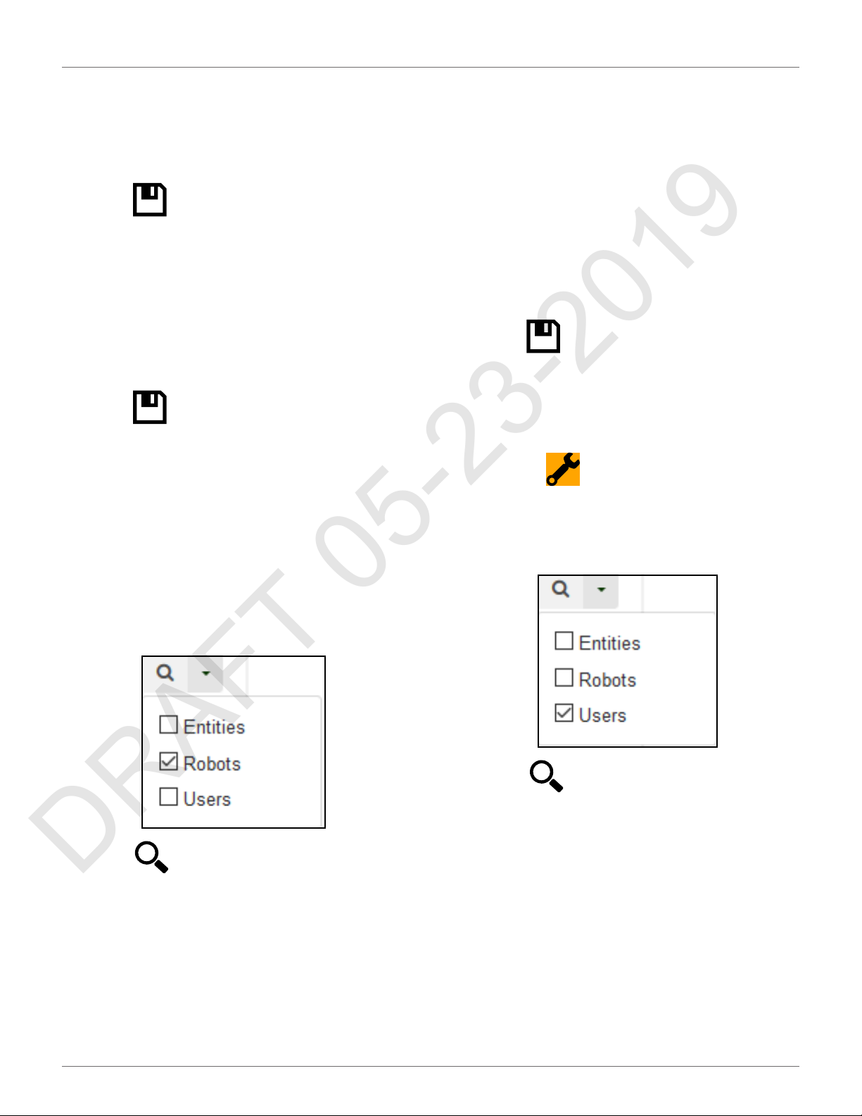
USING THE ROBOT
DRAFT 05-23-2019
CONNECTING TO ROBOTS
To Change the Properties of an Entity
1) Search for the entity.
2) Click on it in the list.
3) Modify the required information.
4) Click (located on the far right-hand side of
the screen).
To Change the Parent Entity
1) Search for the entity.
2) Click on it in the list.
3) Click [Change parent entity]
4) Select the new parent entity.
5) Click (located on the far right-hand side of
the screen).
Managing Robots
NOTE: The information given here, refers to the operations available from the Management section of the
web-server.
To View the Robots in an Entity
To View the Properties of a Robot
1) Click on the robot in the list. The properties of the
robot will be displayed.
To Move a Robot to Another Entity
1) Click on the robot in the list.
2) Click [Change parent entity]. A pop-up window
will appear.
3) Enter the name of the new parent entity, or
choose one from the list. The pop-up window
closes.
4) Click (located on the right hand side of the
screen).
Managing Users
To View the Users in an Entity:
1) Click on .
2) Enter the name (or part of the name) in the
search field. Enter * to search for all users.
3) Set the filter to Users.
1) Enter the name (or part of the name) in the
search field. Enter * to search for all robots.‘
2) Set the filter to Robots.
3) Click . The list of robots and their parent
entity will be displayed.
4) Click . The list of users and their parent
entity will be displayed.
To View the Properties of a User
1) Click on the user in the list. The properties of the
user will be displayed.
NOTE: The properties of a user can not be modified
here. This must be done by the user adapting his
profile.
To Create a New User:
1) Select the parent entity to which the user is to be
added.
2) Click [Create user].
51
Page 56
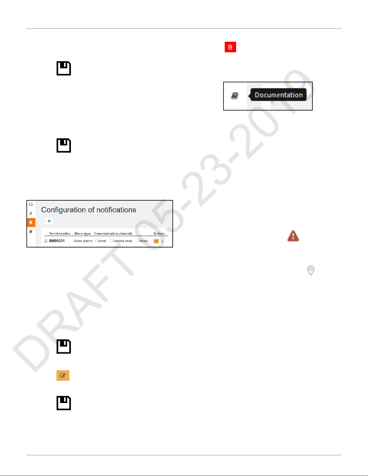
USING THE ROBOT
DRAFT 05-23-2019
CONNECTING TO ROBOTS
3) Enter the details of the new user.
The fields "First name", "Last name" and "E-mail
address" are required.
4) Click .
An email will be sent to the new users email address,
from which the user can activate the account.
To Delete a User:
1) Click on the user in the list.
2) Click X.
3) Click .
7.9.6 Notifications
This section allows the user to set the robot notifications to receive, and the manner in which they will be
delivered.
To Delete a Notification
1) Click .
7.9.7 Documentation
Provides access to the documentation available.
7.9.8 Using the Application
You can view information about your robots using an
application that can be downloaded onto a tablet or a
smartphone.
You can find the application by searching for "ECHO
Robotics" in the application store.
NOTE: Before you can use the application your need to
have set up an account and activated it.
The functionality available from the application is a
subset of the functions available when accessing the
server through a web browser.
To see information about a robot, click on the robot in
the list.
To see the alarm history, click on .
To see the battery level and the robot details, swipe on
To Add a New Notification
1) Click +.
2) Enter the name of the robot (serial number).
3) Select the Notification type.
4) Choose the delivery method:
• Email - to your email address
• Smartphone - the notification can be
viewed in the ECHO Robotics application
5) Click .
To Modify a Notification
1) Click .
2) Modify the notification.
3) Click
the robot.
To see the location of the robot, click on .
7.9.9 Maintenance
Follow all Safety and Information Symbols when
performing maintenance.
Perform maintenance procedures regularly throughout
the mowing season. Have an authorized authorized
ECHO Robotics dealer service the robot once a year.
When maintaining the robot for optimum performance, do not attempt to make any changes to the
robot. Making changes may disturb the robot’s operation, causing an accident, and damaging parts.
NOTE: If unusual operation or physical damage is
noticed, contact an authorized authorized ECHO
Robotics dealer.
IMPORTANT: Keep all nuts, bolts and screws tight to be
sure the robot is in safe working condition.
Always use OEM (Original Equipment Manufacturer)
parts supplied by ECHO Incorporated. In addition to the
risk of accidents, the use of any non-OEM parts will
result in the annulment of the warranty for any
resulting damage. ECHO Incorporated declines all
52
Page 57

USING THE ROBOT
DRAFT 05-23-2019
CONNECTING TO ROBOTS
liability in case of accident due to the use of non-OEM
parts.
Maintenance Chart
Component Weekly 6 months Annual
Cover
Charge contacts
Coil
Bumper
Chassis
Electrical cables Inspect
Front and rear lift
sensors
Front wheels
Rear wheels
Cutting height
system
Cutting heads
Cutting discs
Cutting blades Inspect Replace
Battery Charge
Inspect
/Clean
CleanSonars
Inspect
/Clean
Inspect
/Clean
Inspect
Clean
Winter Service Check List
Basic Information
Client Technician
Serial
number
Date
Field
Installation
date
Service Tests
(indicate condition as appropriate)
Charge
Bumper
Smartbox
Lift Sensors
Backward Sensors
Signal Sensors
Drive Motor (gear
motor)
Cutting Motor
Sonar Sensors
Lid (stop button lid)
Complete two cutting
height tests: highest and
lowest. Check that all
cutting heads go to the
correct height.
Select a trajectory along
a straight line without
obstacles and verify that
the robot follows the
line.
Start the robot, listen for
any abnormal noises.
Check the wheels,
cutting heads, cutting
height motors, rear
wheel motors. Also listen
for excessive body
vibrations.
Service Inspections
(indicate condition as appropriate)
Robot Information (record as appropriate)
Software version
Height of cutting heads
(mm)
Check history on
Myrobot
Perform the service tests listed in the following table.
Access the user interface and select Technician's menu
> Service > Test.
Body
Check the body fixing
screws for rust. Tighten
all screws. If necessary,
replace with A4 type
screw during service.
Check for scratches or
cuts on the bumper.
Verify that all bumper
retention screw are
tight.
Check the integrity of the
sonar electrical
connectors, clean as
necessary.
Clean the charge
contacts.
53
Page 58

USING THE ROBOT
DRAFT 05-23-2019
CONNECTING TO ROBOTS
Service Inspections
(indicate condition as appropriate)
Clean the GUI screen.
Check that there is no
moisture on the exterior
of the screen or
condensation on the
interior of the screen.
Smartbox: If a problem
has been indicated with
the GPS signal, replace
the Smartbox.
Inspect the inside of the
cover and the chassis:
• • cable condition
(check for cuts or
abrasions)
• • attachment and
routing of cables
• • cable electrical
connections
• • inspect for
corrosion on the
chassis
• • check the JEA40
connector for
corrosion
• • check the
charge connector
for corrosion
Frame
Verify that the coil is
securely tightened to the
chassis. Check the coil
electrical connector.
Check that the front
wheel axles rotate freely
and the axle nuts are
securely tightened.
Front wheels: check the
rotation, wheels should
spin freely without
wobbling. Verify that the
wheel bearings are
sealed.
Check the rear tires for
excessive wear, replace
as necessary.
(indicate condition as appropriate)
Front lift sensors: verify
that the lift sensors
move up and down with
no resistance, lubricate
as necessary.
Check the front and rear
silentblocs for cracking
or splitting, replace as
necessary. Replace the
silentblocs once every
two years regardless of
their condition.
Cutting heads and
cutting system:
•
• cable condition
(check for cuts or
abrasions)
• • check the lifting
strap
• • check for moisture in the interior of the cutting
motor housing
(always replace
the top seal when
servicing the
cutting motor
housing)
• • check for excessive lateral movement of the
cutting head
upper and lower
brackets
• • verify that the
cutting disc spins
freely and does
not wobble
• •verify that the
anti-friction disc
spins freely (this
disc must spin
independently
from the cutting
disc).
Service Inspections
54
Page 59
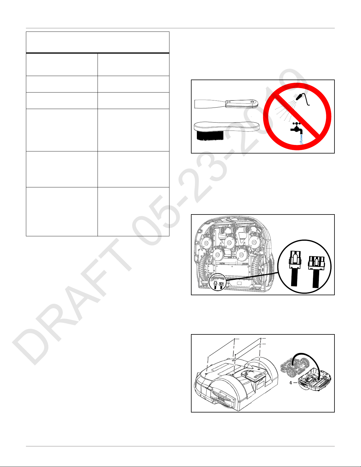
MAINTENANCE PROCEDURES
DRAFT 05-23-2019
GENERAL INSPECTION AND CLEANING
Service Inspections
(indicate condition as appropriate)
Inspect the cutting
blades, replace if dull,
cracked, or chipped.
Inspect the cutting head
motor.
Inspect the backwards
sensors.
Inspect all electrical
cables for cuts or
abrasions. Verify that all
connectors are securely
assembled. Replace
damaged cables.
Electrical box: check
cable connections,
inspect the interior for
the presence of
moisture.
Drive motor: Lubricate
the motors during every
service. Check and
replace the axle, bearing
and the seal on the
outlet of the gear unit if
necessary.
6) Use a plastic scraper, nylon brush, compressed
air, or a damp cloth to clean dirt, grass, sticks, or
obstructions.
NOTE: Do not use a high-pressure washer or running
water for cleaning. Never use solvents.
8.2 Cover and Electrical Cables
1) Clean the outside of the cover.
2) Stand the robot on end. Disconnect the two electrical cables (located in circled area).
8 Maintenance Procedures
8.1 General Inspection and
Cleaning
During periods of wet weather, perform inspection and
cleaning once per day.
1) Move the power switch to the OFF position.
2) De-energize AC power at the mains (charging
station only).
3) Remove robot from charging station (if
required).
4) Visually inspect the unit, replace damaged
components.
5) Check all electrical connectors, reconnect if
necessary.
3) Lay the robot back onto flat ground.
4) Remove the front cover screws, rear cover
screws, rear washers, and cover.
1
1 – Front cover screw (2X)
2 – Rear cover screw (2X)
3 – Rear washer (2X)
4 – Cover
2
3
4
55
Page 60

MAINTENANCE PROCEDURES
DRAFT 05-23-2019
CHARGE CONTACTS
5) Lift the cover off and turn it over.
6) Clean the inside of the cover, clean all electrical
cables.
7) Place the cover onto the chassis.
8) Assemble the cover screws and washers. Tighten
the screws to 5 lbf•ft (7 N•m).
9) Stand the robot on end.
10) Connect the electrical cables.
11) Lay the robot back onto flat ground.
8.3 Charge Contacts
Clean once per week.
8.5 Coil
Clean once per week.
1) Visually inspect the coil for damage.
2) Inspect the cable. If there are exposed wires,
replace the cable.
1 2
1 – Right side charge contact
2 – Left side charge contact
8.4 Sonar Sensors and Bumper
Clean once per week. Check that the bumper material
is intact and not cut or torn. If the bumper is damaged,
replace it.
1
1
8.6 Chassis
Clean once per week.
Remove the cover to access the chassis.
1 2
1 – Sonar sensors (5X)
2 – Bumper
56
1
1
Page 61

MAINTENANCE PROCEDURES
DRAFT 05-23-2019
FRONT AND REAR LIFT SENSORS
8.7 Front and Rear Lift Sensors
Clean once per week. Verify that the front lift sensors
move up and down with no resistance.
1
1
1
1
3
3
2
8.8 Front Wheel Assemblies
Verify that the wheels (and wheel axle) rotate easily.
Clean the front wheel assemblies once per week.
2
1
1 – Wheel
2 – Wheel axle
8.9 Rear Wheels and Rear Wheel
Brushes
2
2 3
1 – Lift sensor attachment point
2 – Front lift sensor assembly
3 – Rear lift sensor assembly
Clean the rear wheels and rear wheel brushes (if
installed) once per week.
1
1
2
2
1 – Rear wheel
2 – Wheel brush
57
Page 62

SERVICE PROCEDURES
DRAFT 05-23-2019
CUTTING HEIGHT SYSTEM
8.10 Cutting Height System
Clean the cutting height system once per week. Rotate
the lifting axle by hand and verify that the cutting heads
move up and down smoothly.
1
1 – Lifting axle
8.12 Winter Storage
• Charge the battery to 100% before storing.
• Complete all weekly, 6 month, and annual maintenance procedures.
• Schedule service procedures with an authorized
ECHO Robotics dealer (if required).
• Store the robot in a protected dry location where
the temperature is above 32° F (0° C).
At the start of a new season:
1) Move the power switch to the ON position.
2) Place the robot onto the charging station and
allow the battery to fully charge.
3) Run the robot as normal and observe for correct
operation.
9 Service Procedures
8.11 Cutting Heads
SHARP BLADES
Contact with cutting blades can result in cutting of
fingers or hands.
• Wear protective gloves when handling the robot.
Clean the cutting head assemblies once per week.
Verify that the cutting head assemblies move smoothly
up and down and the cutting discs and anti-friction
discs rotate freely. The cutting head should not have an
excessive amount of lateral movement.
1 1
1
SHARP BLADES
Contact with cutting blades can result in cutting of
fingers or hands.
• Wear protective gloves when handling the robot.
Follow all Safety and Information Symbols on the robot.
Only use an authorized ECHO Robotics dealer for
service procedures.
Genuine ECHO Robotics parts and assemblies for ECHO
Robotics products are available only from an authorized ECHO Robotics dealer. Always supply a model and
serial number when purchasing parts and assemblies.
Move the power switch to the OFF position before
starting any service procedures.
1 1
1 – Cutting head assembly (5X)
2 – Cutting disc (one per cutting head assembly)
58
2
Page 63

SERVICE PROCEDURES
DRAFT 05-23-2019
SONAR REPLACEMENT
9.1 Sonar Replacement
1) Remove the cover.
2) Disconnect the sonar cables and push the sonars
out of the cover (from inside out).
3) Insert and securely seat the replacement sonars
into the cover.
4) Remove the bumper assembly.
5) Assemble the new bumper assembly to the
cover.
6) Assemble the bumper retaining screws, tighten
to 1.5 lbf• ft (2 N•m).
7) Connect the bumper cable to the bumper.
8) Complete the Bumper Service Test.
4) Connect the sonar cables and replace the cover.
5) Complete the Sonar Sensor Service Test.
9.2 Bumper Replacement
NOTE: Left side cut-away view of cover shown.
1) Remove the cover.
2) Disconnect the bumper cable from the bumper.
3) Remove the bumper retaining screws.
2
9.3 Front Lift Cushion
Replacement
NOTE: Detail of left side shown.
1) Remove the flexible cap and the screw.
2) Remove the front lift cushion.
3) Assemble the new front lift cushion in the original location.
4) Assemble the screw, tighten to 4.5 lbf•ft
(6 N•m).
5) Replace the flexible cap.
6) Complete the Lift Sensor Service Test.
3
3
1
1 – Bumper cable
2 – Bumper retaining screw (11X)
1 – Flexible cap
2 – Screw
3 – Cushion
3
2
1
59
Page 64
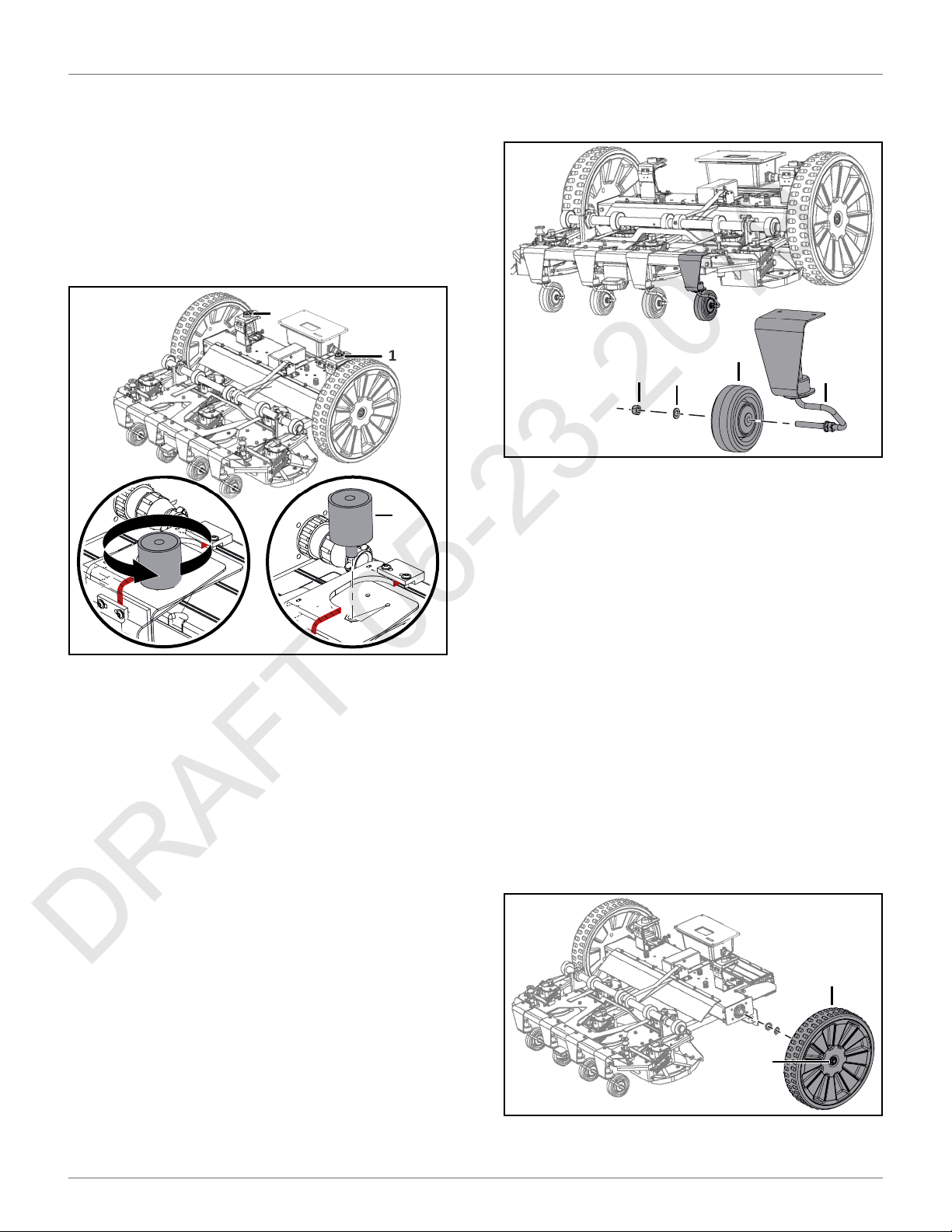
SERVICE PROCEDURES
DRAFT 05-23-2019
REAR LIFT CUSHION REPLACEMENT
9.4 Rear Lift Cushion
Replacement
1) Remove the cover.
2) Remove the rear lift cushion.
3) Assemble the new rear lift cushion.
4) Complete the Lift Sensor Service Test.
1
3) Assemble the washer and nut. Tighten the nut to
7.5 lbf•ft (10 N•m).
1
1
2
1 – Nut
1
2 – Washer
3 – Wheel
4 – Axle
3
4
1 – Rear lift cushion
9.5 Front Wheel Replacement
1) Remove the nut, washer, and wheel from the
axle.
2) Assemble the new wheel to the axle.
9.6 Rear Wheel Replacement
1) Remove the cover.
2) Loosen the wheel nut and remove the rear wheel
assembly and washers from the gear motor
output shaft. Discard the washers. The wheel nut
remains captive with the rear wheel assembly.
3) Place new washers on the gear motor output
shaft. Do not reuse old washers.
4) Apply Loctite® 243 Blue Threadlocker to the interior threads of the wheel nut. Place the rear
wheel assembly onto the gear motor output
shaft, tighten the nut to 48 lbf•ft (65 N•m).
2
1
1 – Wheel nut
2 – Wheel assembly
60
Page 65

SERVICE PROCEDURES
DRAFT 05-23-2019
GEAR MOTOR REPLACEMENT
9.7 Gear Motor Replacement
Bottom view of robot shown.
1) Remove the rear wheel and washers. Discard the
washers.
2) Remove the six screws and cover from the electrical box.
5) Remove the gear motor assembly.
1
1 – Gear motor assembly
6) Remove the four screws from the gear motor,
then remove the c-clip from the output shaft.
Remove the gear motor from the bracket
assembly.
3
4
2
1
1 – Screw
2 – Cover
3) Disconnect the gear motor cables from the traction drive card.
4) Remove the six bolts from the gear motor
support.
2
1
1 – Bolt
2 – Gear motor support
1
2
1 – Screw
2 – C-clip
3 – Gear motor
4 – Bracket assembly
7) Place new motor into the bracket assembly.
Assemble the four mounting bolts, tighten to
4.5 lbf•ft (6 N•m). Replace the clip on the output
shaft.
8) Use compressed air to remove any moisture
from the inside of the electrical box.
9) Place the new motor and bracket assembly into
the electrical box.
10) Assemble the six bolts to the gear motor support.
11) Reconnect the gear motor cables to the traction
drive card.
12) Assemble the electrical box cover onto the electrical box.
13) Place new washers on the gear motor output
shaft. Do not reuse old washers.
14) Assemble the rear wheel.
15) Complete the Drive Motor Service Test.
61
Page 66
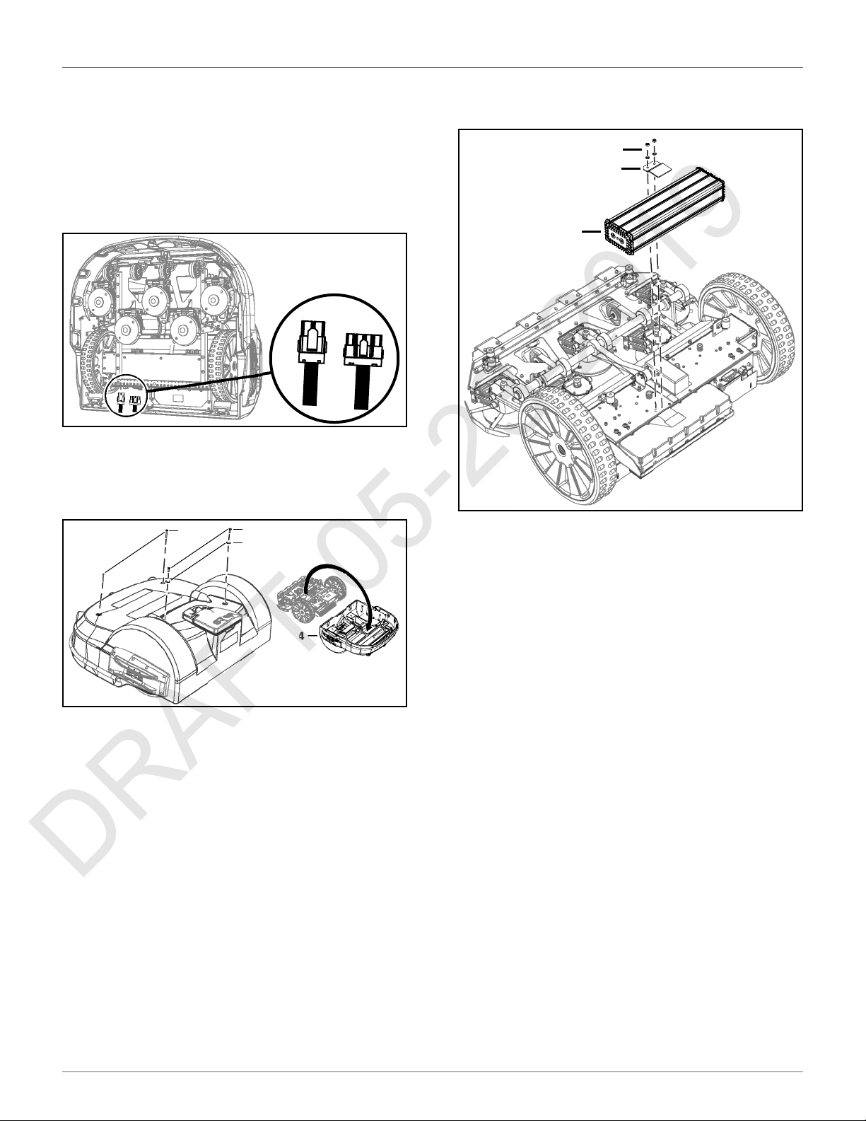
SERVICE PROCEDURES
DRAFT 05-23-2019
BATTERY REMOVAL AND INSTALLATION
9.8 Battery Removal and
Installation
NOTE: TM-2000 shown.
Removal:
1) Stand the robot on end. Disconnect the two electrical cables (located in circled area).
2) Lay the robot back onto flat ground.
3) Remove the front cover screws, rear cover
screws, rear washers, and cover.
5) Remove the battery fastener nuts, washers,
battery fastener, and battery.
1
2
3
1
1 – Front cover screw (2X)
2 – Rear cover screw (2X)
3 – Rear washer (2X)
4 – Cover
4) Disconnect the battery cable from the battery.
2
3
4
1 – Nuts, washers
2 – Battery fastener
3 – Battery
Installation:
1) Place the new battery in the robot.
2) Assemble the battery fastener, washers, and
nuts.
3) Connect the battery cable to the battery.
4) Place the cover on the robot.
5) Assemble the cover screws and washers. Tighten
screws to 5 lbf• ft (7 N•m).
6) Stand the robot on end.
7) Re-connect the two electrical cables.
8) Lay the robot back onto flat ground.
9) Complete the Charge Service Test.
62
Page 67
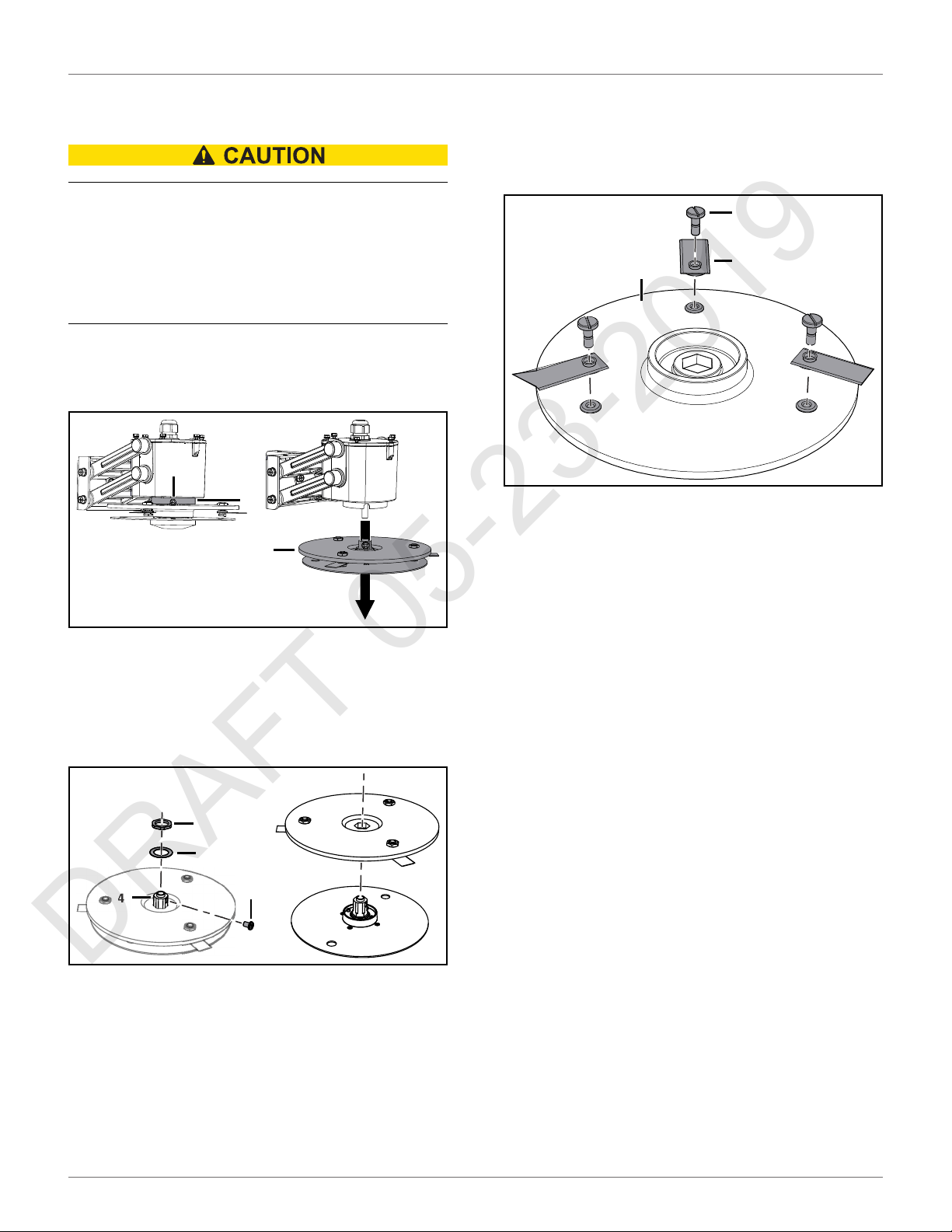
SERVICE PROCEDURES
DRAFT 05-23-2019
CUTTING DISK SERVICE
9.9 Cutting Disk Service
SHARP BLADES
Contact with cutting blades can result in cutting of
fingers or hands.
• Wear protective gloves when handling the robot.
1) Rotate the cutting head so the retention screw
aligns with the slot in the guard. Loosen the
retention screw to remove the cutting head.
1
2
3
9.10 Blade Replacement
1) Remove the blades from the upper cutting disc.
Replace the blades, tighten the screws to
1.5 lbf•ft (2 N•m).
1
3
1 – Screw
2 – Blade
3 – Upper cutting disc
2
1 – Retention screw
2 – Guard
3 – Cutting head
2) Remove the retention screw, nut, and washer
from the cutter shaft. Separate the two discs.
2
3
4
1 – Retention screw
2 – Nut
3 – Washer
4 – Cutter shaft
1
63
Page 68
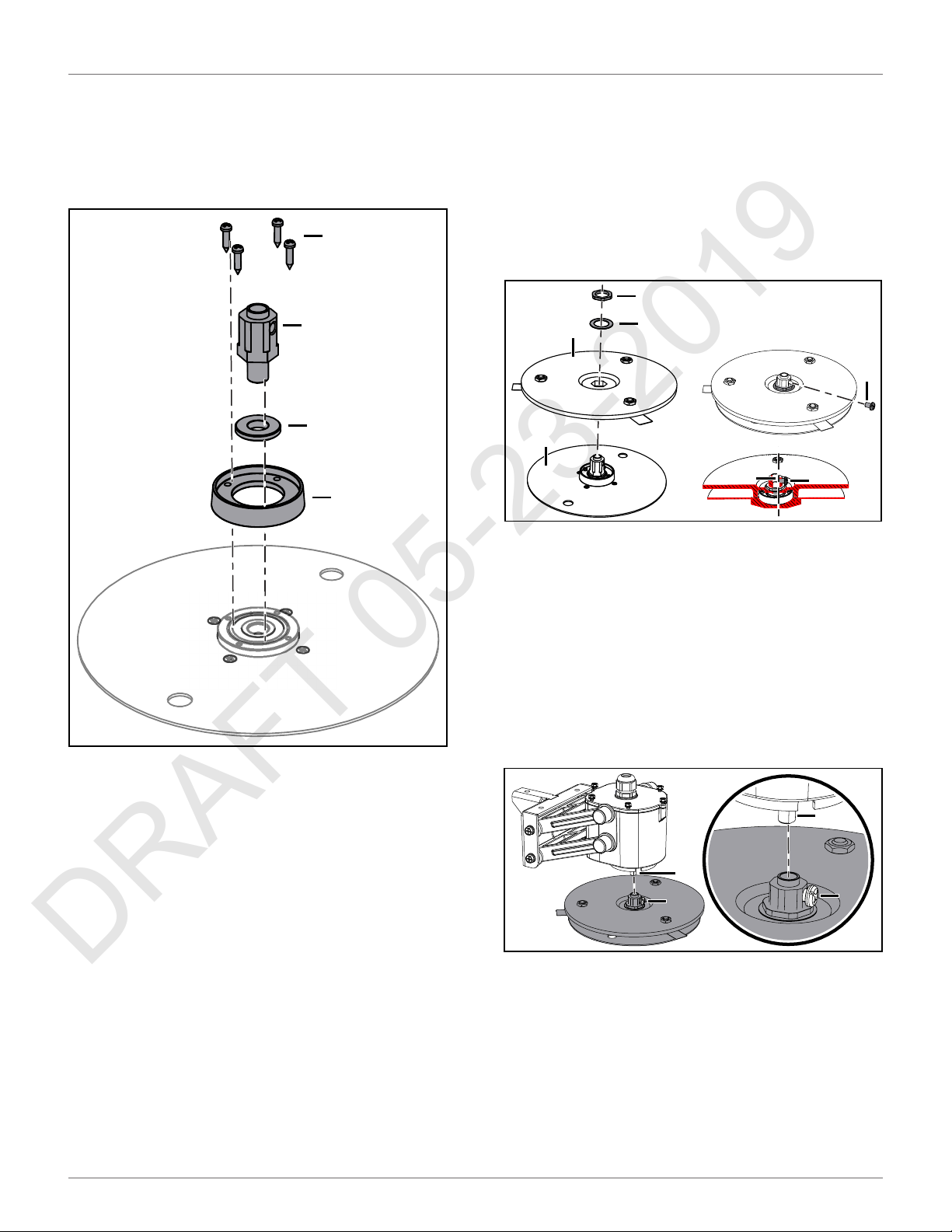
SERVICE PROCEDURES
DRAFT 05-23-2019
ALUMINUM ANTI-FRICTION DISC REPLACEMENT
9.11 Aluminum Anti-friction Disc
Replacement
1) Remove the four screws from the cap, then
remove the cutter shaft, collar, and cap.
1
3
4
2
9.12 Cutting Head Reassembly
1) Place the cutting disc onto the anti-friction disc.
2) Assemble the washer and nut onto the cutter
shaft, tighten the nut to 15 lbf•ft (20 N•m).
3) Assemble the screw to the cutter shaft.
NOTE: Do not allow the screw to extend into the
center of the cutter shaft.
4
1
2
1 – Cutting disc
2 – Anti-friction disc
3 – Washer
4 – Nut
5 – Screw
6 – Center of cutter shaft
3
5
6
5
4) Place the assembled cutting head back onto the
cutting head axle. NOTE: Align the screw with the
flat surface of the cutting head axle.
5) Tighten the screw to 4.5 lbf•ft (6 N•m).
1 – Screw
2 – Cap
3 – Cutter shaft
4 – Collar
2) Place the new disc on a flat surface.
3) Assemble the cap to the disc using the four
screws.
4) Securely seat the collar into the cap.
5) Securely seat the cutter shaft into the disc.
2
1
1 – Screw
2 – Flat surface of cutting head axle
2
1
64
Page 69

SERVICE PROCEDURES
DRAFT 05-23-2019
CUTTING MOTOR SERVICE
9.13 Cutting Motor Service
1) Remove the screws, bracket, cap, and gasket
from the motor case. NOTE: Slowly lift the cap off
from the motor case. Do not pull the wiring.
2) Inspect the interior of the motor case the cutting
drive card for condensation or water accumulation. Use compressed air to dry as necessary.
3) Reassemble the gasket, cover, bracket, and
screws to the motor case. Tighten the screws to
1.0 lbf•ft (1.5 N•m).
2
1 1
1
3
4
9.15 Correcting Stop Button Lid
Closure Problems
The stop button lid needs to be properly closed before
the robot can perform its specified missions. On occasions, even when the cover has been closed properly,
the robot does not start its mission and the message
"Lid not closed, please select option again" is displayed.
In order for the robot to be able to execute its missions
the lid needs to be shut, and to form a closed circuit
between magnets on the lid and relays on the body.
This circuit needs to be open when the lid is open.
When the lid is pressed down, it acts as the stop
button. This requires that all magnets and relays are
functioning correctly, and there is precision in their
positioning.
The next figure shows a representation of the lid, body,
magnet, and relays. There are two magnets on the lid
and two sets of relays on the body.
A - Rear view of robot with lid open.
1
1 1
7
1 – Cutting head assembly on robot (5X)
2 – Screw
3 – Bracket
4 – Cap
5 – Gasket
6 – Motor case
7 – Cutting drive card (located in motor case)
4) Complete the Cutting Motor Service Test.
9.14 Cutting Motor Cable
5
2
6
1
2
3 3
1 – Stop button lid
2 – Magnet
3 – Relays
4 – Body (cover of robot)
NO
NC
4
3
2
Replacement
1) Visually inspect the cables for cuts or abrasions.
2) Replace damaged cables.
3) Replace cable retention clips if necessary.
65
Page 70
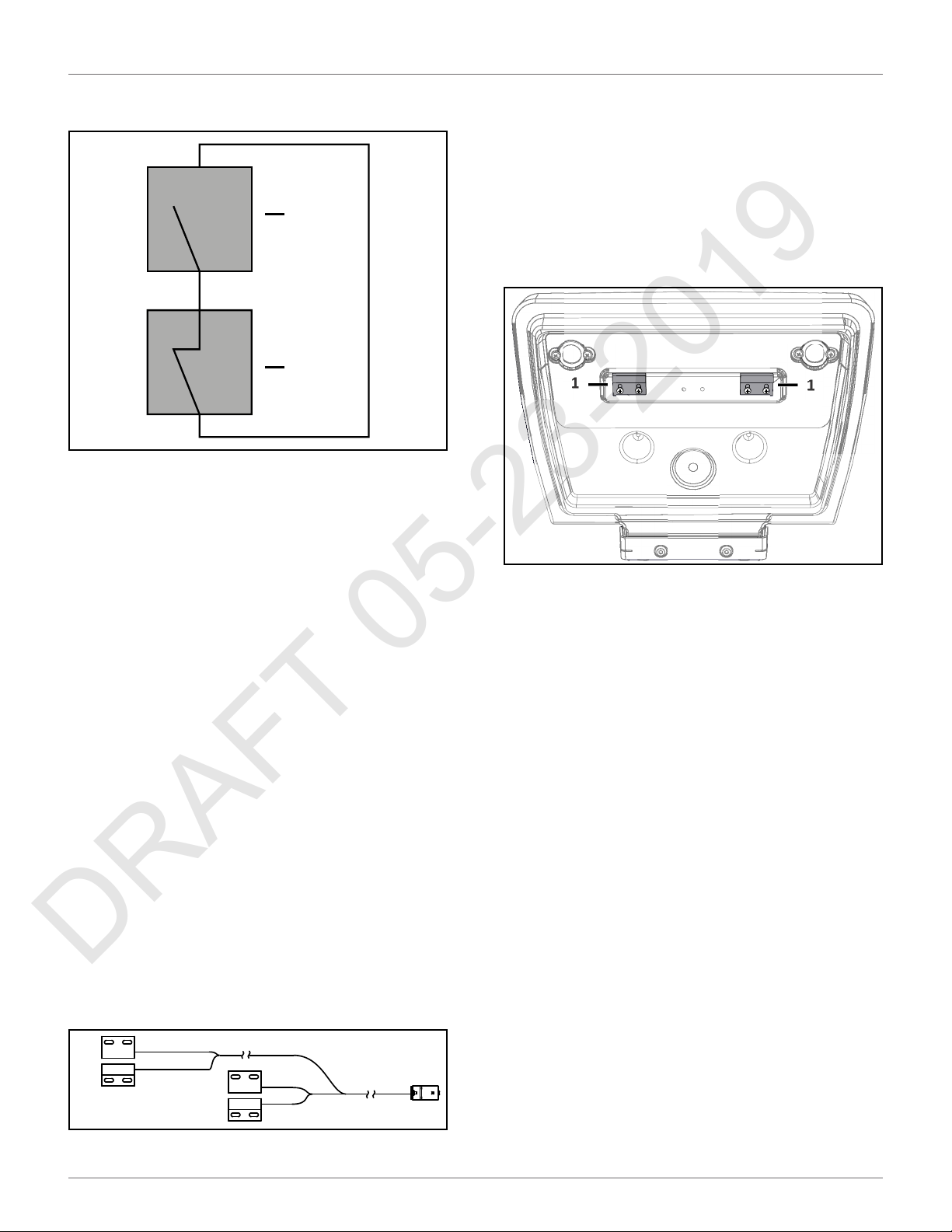
SERVICE PROCEDURES
DRAFT 05-23-2019
CORRECTING STOP BUTTON LID CLOSURE PROBLEMS
One relay is "Normally Open" (NO), the other is
"Normally Closed" (NC). The circuit is shown below.
NO
NC
1 – Relay (NO - normally open)
2 – Relay (NC - normally closed)
When the lid is closed the magnet must be in a position
to align with the reed relays on the cover. This alignment allows the circuit to close and the robot to
operate.
When the lid is open, the circuit is open, preventing the
robot from operating.
When the lid is closed and pressed down, the roles of
the two relays are reversed and the circuit is open,
preventing the robot from operating.
If there are problems with the lid closure, run a service
test. Select Service > Tests > Lid from the service menu.
1
2
When installing replacement magnets and relays, visually examine the position to ensure correct alignment.
Run the service test to ensure the relays correctly align
to the magnets. Select Service > Tests > Lid from the
service menu.
9.15.2 Magnets
Assemble the magnets to the lid at the positions shown
in the figure below.
1
1 – Magnets
The magnets must be at the correct height so that
when the lid is closed or pressed down they connect
with the correct relays. If necessary, spacers must be
placed behind the magnets. Run the service test to
ensure the magnets correctly align to the relays. Select
Service > Tests > Lid from the service menu.
1
9.15.1 Relays
The pairs of relays must be installed one above the
other in the correct order:
NO must be on top. This relay is identified as having the
digit “1” in the reference number.
NC must be on the bottom. This relay is identified as
having the digit “4” in the reference number.
NOTE: The reference numbers are etched on the
surface of the relays.
The relays are supplied as an assembly. The assembly
contains two pairs of relays and the cabling between
them.
NO
NC
66
NO
NC
Page 71
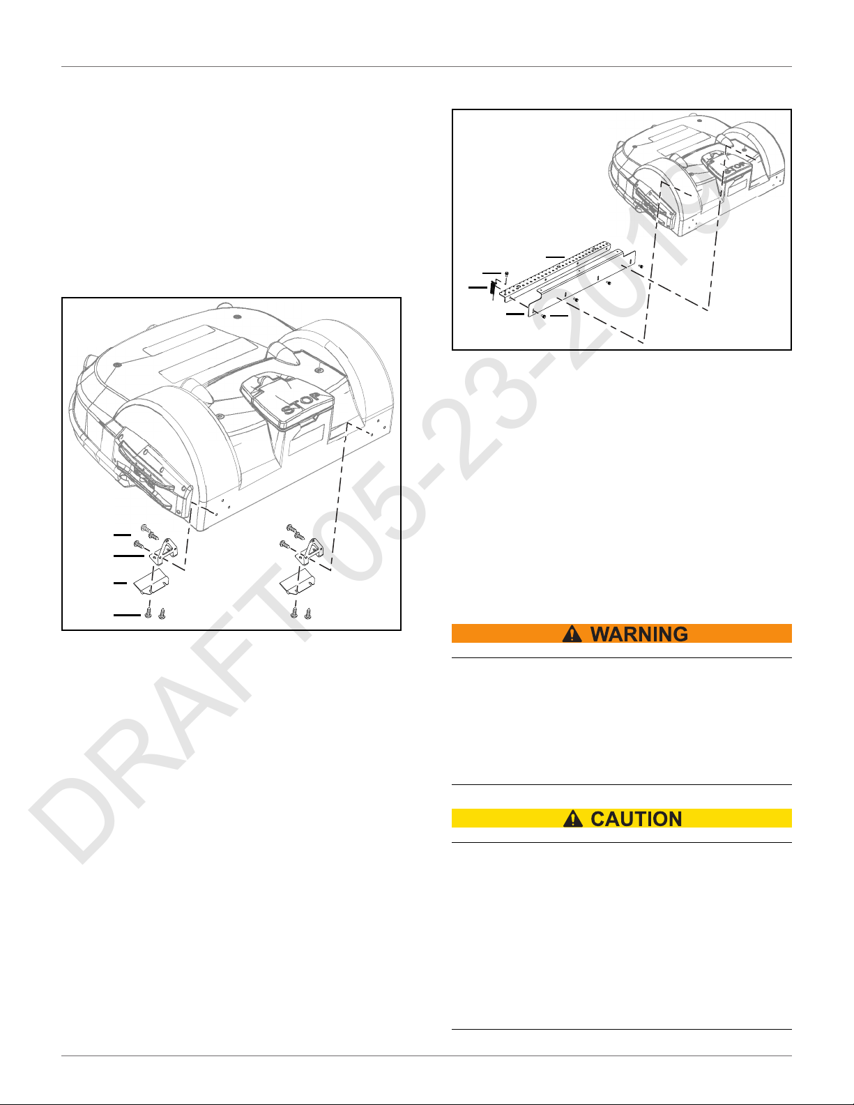
ROBOT ACCESSORIES
DRAFT 05-23-2019
WHEEL BRUSH KIT
10 Robot Accessories
10.1 Wheel Brush Kit
Assemble the wheel brush kit to the inside rear of the
cover behind each rear wheel.
1) Assemble the wheel brush to the brush holder.
2) Assemble the brush holder to the inside rear of
the cover behind each rear wheel.
2) Assemble the groomer support to the rear guard.
4
3
2
1
1 – Rear guard plate
2 – Springs (28X)
3 – Screw M6 x 16 (32X)
4 – Groomer support
3
3
2
1
3
1 – Wheel brush
2 – Brush holder
3 – Screw M6 x 16 (10X)
10.2 Groomer Kit
Assemble the groomer kit to the rear guard of the
robot. The rear guard is factory assembled to the
bottom of the robot’s chassis.
1) Assemble the springs to the support bar.
11 Battery Service and Installation
SAVE THESE INSTRUCTIONS – This document contains
important safety and operating instructions for the
Lithium-ion battery.
PERSONAL INJURY HAZARD
Failure to follow all instructions listed in this document can lead to serious personal injury.
• Read and understand all instructions prior to
servicing the battery.
RISK OF FIRE, ELECTRIC SHOCK, AND
BURNS
Do not crush, heat above 140 °F (60 °C), incinerate,
short circuit, dismantle, or immerse the battery in
any liquid. Do not charge below 32 °F (0 °C).
• Refer to the operator’s manual for battery recycling instructions. Only use the charger specified in the technical manual.
67
Page 72
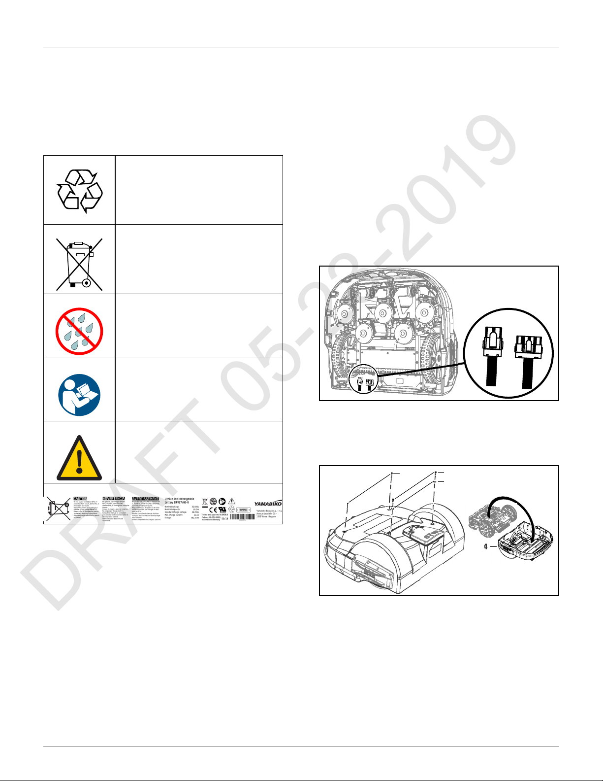
BATTERY SERVICE AND INSTALLATION
DRAFT 05-23-2019
SAFETY INFORMATION
NOTE: Federal law prohibits transport or shipment of
these batteries aboard passenger aircrafts or other
vessels. Abide by all federal and local regulations for
the safe transport of Lithium-ion batteries.
11.1 Safety Information
Recycle the battery if it is damaged
or does not operate correctly.
Li-Fe
Do not dispose of the battery in a
non-approved container.
Do not allow water on the battery.
Do not service the battery in wet
conditions.
rized ECHO Robotics Technician to check the condition
of the battery.
NOTE: It is possible to monitor the work cycles using
the portal.
Monitor the work cycles at the end of each mowing
season.
11.3 Battery Removal and
Installation
NOTE: TM-2000 shown.
Removal:
1) Stand the robot on end. Disconnect the two electrical cables (located in circled area).
Read the technical manual before
servicing the battery.
Caution: The battery can be
dangerous of misused.
NOTE: Electrolyte may leak from the battery if it is
damaged or not used properly. In the event of accidental contact:
• wash affected areas of skin with soap and water
• rinse eyes with water for a minimum of 15
minutes
To obtain a battery Material Safety Data Sheet, send an
email request to: admin@echorobotics.com.
11.2 Operation
2) Lay the robot back onto flat ground.
3) Remove the front cover screws, rear cover
screws, rear washers, and cover.
1
1 – Front cover screw (2X)
2 – Rear cover screw (2X)
3 – Rear washer (2X)
4 – Cover
4) Disconnect the battery cable from the battery.
2
3
4
The automatic operation of the robot optimizes battery
life. Allow the robot to manage its work cycles. If these
work cycles seem unusually short, contact an autho-
68
Page 73

BATTERY SERVICE AND INSTALLATION
DRAFT 05-23-2019
REMOVAL AND INSTALLATION (RP-1200)
5) Remove the battery fastener nuts, washers,
battery fastener, and battery.
1
2
3
11.4 Removal and Installation
(RP-1200)
PINCH AND CUT HAZARD
Allowing the rear panel and battery to drop freely
can pinch or cut fingers and hands.
• Hold the rear panel when removing the rear
panel retention screws. Slowly lower the rear
panel and battery after removing the screws.
Removal:
1) Remove the rear panel retention screws (3X).
2) Slowly open the rear panel and allow it to rest on
the ground.
3) Disconnect the battery cable from the battery.
4) Remove the battery bracket nuts (3X), and the
battery bracket.
1 – Nuts, washers
2 – Battery fastener
3 – Battery
Installation:
1) Place the new battery in the robot.
2) Assemble the battery fastener, washers, and
nuts.
3) Connect the battery cable to the battery.
4) Place the cover on the robot.
5) Assemble the cover screws and washers. Tighten
screws to 5 lbf• ft (7 N•m).
6) Stand the robot on end.
7) Re-connect the two electrical cables.
8) Lay the robot back onto flat ground.
9) Complete the Charge Service Test.
5) Remove the battery.
Installation:
1) Place the new battery onto the rear panel.
2) Assemble the battery bracket over the battery.
3) Assemble battery bracket nuts (3X).
4) Connect the battery cable to the battery.
5) Close the rear panel.
6) Assemble the rear panel screws (3X).
7) Complete the Charge Service Test.
11.5 Storage
Prior to storage:
• Move the robot to the charging station, allow the
battery to completely charge.
• Move the main power switch for the robot to the
OFF position.
• Disconnect the battery cable from the battery.
69
Page 74

TORQUE REFERENCES
DRAFT 05-23-2019
RECYCLING
11.6 Recycling
Li-Fe
non-operational.
non-approved container.
If there are no accredited facilities available to recycle
batteries, check with your authorized ECHO Robotics
Dealer or local government agency for proper battery
disposal procedures.
Recycle the battery if it is damaged or
Do not dispose of the battery in a
12 Torque References
IMPORTANT: The values in the following table apply
only when a specific torque for a fastener is not listed.
Size lbf•ft N•m
No. 6 0.58 - 0.83 0.8 - 1.1
No. 8 1.25 - 1.83 1.7 - 2.5
No. 10 2.0- 3.0 2.7 - 4.0
No. 12 3.0 - 4.0 4.0 - 5.4
M3 1.25 - 1.83 1.7 - 2.5
M4 2.0 - 2.9 2.7 - 4.0
M5 2.9 - 5.0 4.0 - 6.8
M6 7.0- 8.8 9.5 - 12.0
M8 14.7 - 17.0 20.0 - 23.0
M10 25.8 - 28.0 35.0 - 38.0
70
Page 75
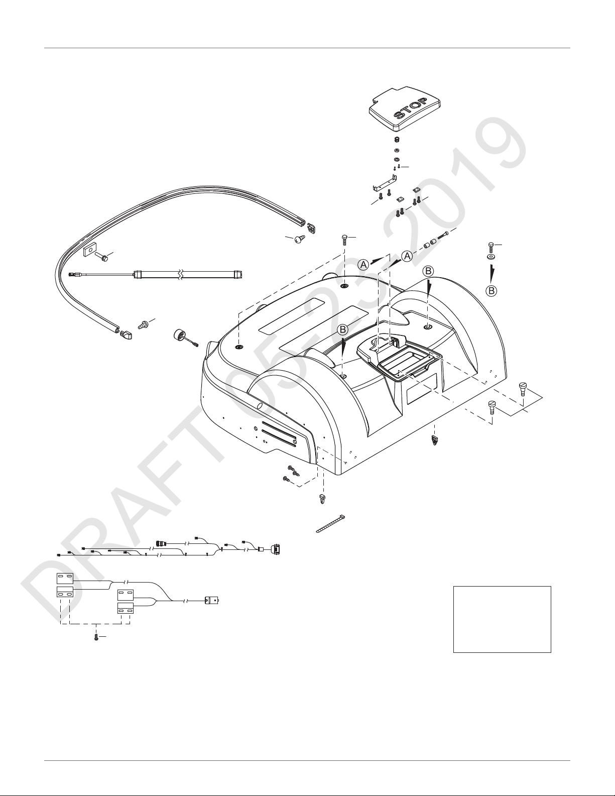
12.1 Mower Body
DRAFT 05-23-2019
1.5 lbf·Ō
(2 N·m)
1.5 lbf·Ō
(2 N·m)
1.5 lbf·Ō
(2 N·m)
1.5 lbf·Ō
(2 N·m)
†
5 lbf·Ō
(7 N·m)
<1 lbf·Ō
(<0.7 N·m)
<1 lbf·Ō
(<0.7 N·m)
1.5 lbf·Ō
(2 N·m)
TORQUE REFERENCES
MOWER BODY
†
5 lbf·Ō
(7 N·m)
<1 lbf·Ō
(<0.7 N·m)
1.5 lbf·Ō
(2 N·m)
†
Loctite 243
Blue Threadlocker
††
Loctite 2701
Green Threadlocker
†
71
Page 76

TORQUE REFERENCES
DRAFT 05-23-2019
CUTTING HEIGHT
12.2 Cutting Height
18 lbf·Ō
(3 N·m)
18 lbf·Ō
(3 N·m)
2 lbf·Ō
(3 N·m)
1-1.5 lbf·Ō
(1.5-2.0 N·m)
1 lbf·Ō
(1.5 N·m)
1-1.5 lbf·Ō
(1.5-2.0 N·m)
1 lbf·Ō
(1.5 N·m)
9 lbf·Ō
(12 N·m)
18 lbf·Ō
(3 N·m)
1 lbf·Ō
(1.5 N·m)
†
1 lbf·Ō
(1.5 N·m)
4.5 lbf·Ō
(6 N·m)
1 lbf·Ō
(1.5 N·m)
1 lbf·Ō
(1.5 N·m)
†
†
9 lbf·Ō
(12 N·m)
1 lbf·Ō
(1.5 N·m)
0.7 - 1.5 lbf·Ō
(1 - 2 N·m)
9 lbf·Ō
(12 N·m)
†
Loctite 243
Blue Threadlocker
††
Loctite 2701
Green Threadlocker
72
Page 77

12.3 Electrical Box, Battery, and Housing
DRAFT 05-23-2019
2 lbf·Ō
(3 N·m)
2 lbf·Ō
(3 N·m)
2 lbf·Ō
(3 N·m)
A
9 lbf·Ō
(12 N·m)
11 lbf·Ō
(15 N·m)
†
A
TORQUE REFERENCES
ELECTRICAL BOX, BATTERY, AND HOUSING
2 lbf·Ō
11 lbf·Ō
(15 N·m)
†
(3 N·m)
†
9 lbf·Ō
(12 N·m)
†
9 lbf·Ō
(12 N·m)
†
9 lbf·Ō
(12 N·m)
†
Loctite 243
Blue Threadlocker
††
Loctite 2701
2 lbf·Ō
(3 N·m)
Green Threadlocker
73
Page 78

TORQUE REFERENCES
DRAFT 05-23-2019
LIFT SENSORS
12.4 Lift Sensors
2 lbfÂft
(3 NÂP
†
2 lbfÂft
(3 NÂP
††
1 lbfÂft
(1.5 NÂP
4.5 lbfÂft
(6 NÂP
†
†
0.7-1.0 lbfÂft
(1-1.5 NÂP
†
†
Loctite 243
Blue Threadlocker
††
Loctite 2701
Green Threadlocker
0.7-1.0 lbfÂft
(1-1.5 NÂP
†
9 lbfÂft
(12 NÂP
1 lbfÂft
(1.5 NÂP
†
74
Page 79

12.5 Wheels, Motor and Gear Box
DRAFT 05-23-2019
9 lbf·Ō
(12 N·m)
0.75 - 1.0 lbf·Ō
(1.0 - 1.5 N·m)
†
TORQUE REFERENCES
WHEELS, MOTOR AND GEAR BOX
7.5 lbf·Ō
(10 N·m)
7.5 lbf·Ō
(10 N·m)
7.5 lbf·Ō
(10 N·m)
48 lbf·Ō
(65 N·m)
4.5 lbf·Ō
(6 N·m)
2 lbf·Ō
††
(3 N·m)
†
†
Loctite 243
Blue Threadlocker
††
Loctite 2701
Green Threadlocker
75
Page 80

12.6 Cutting Head
DRAFT 05-23-2019
1.0-1.5 lbf·Ō
(1.5-2.0 N·m)
4.5 lbf·Ō
(6 N·m)
4.5 lbf·Ō
(6 N·m)
TORQUE REFERENCES
CUTTING HEAD
A
1.5 lbf·Ō
†
(2 N·m)
1.5 lbf·Ō
†
(2 N·m)
†
15 lbf·Ō
†
(20 N·m)
††
3.7-5.0 lbf·Ō
(5-7 N·m)
3.7-5.0 lbf·Ō
(5-7 N·m)
†
†
9 lbf·Ō
(12 N·m)
4.5-6.0 lbf·Ō
(6-8 N·m)
†
0.75-1.5 lbf·Ō
(1-2 N·m)
4.5-6.0 lbf·Ō
4.5-6.0 lbf·Ō
(6-8 N·m)
(6-8 N·m)
†
†
3.5-5.0 lbf·Ō
†
Loctite 243
(5-7 N·m)
†
Blue Threadlocker
††
Loctite 2701
Green Threadlocker
A
76
Page 81
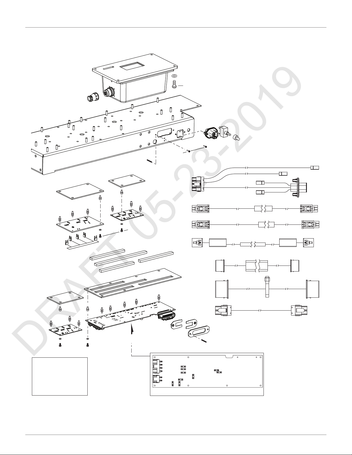
12.7 Electrical Parts
DRAFT 05-23-2019
TORQUE REFERENCES
ELECTRICAL PARTS
B
1 lbfÂft
(1.5 NÂP
2 lbfÂft
(3 NÂP
1 lbfÂft
(1.5 NÂP
†
View A
B
†
Loctite 243
Blue Threadlocker
††
Loctite 2701
Green Threadlocker
View A
77
Page 82

TORQUE REFERENCES
DRAFT 05-23-2019
MAIN FRAME
12.8 Main Frame
9 lbfÂft
(12 NÂP
1 lbfÂft
(1.5 NÂP
†
1 lbfÂft
(1.5 NÂP
†
†
9 lbfÂft
(12 NÂP
†
4.5 lbfÂft
(6 NÂP
9 lbfÂft
(12 NÂP
†
9 lbfÂft
(12 NÂP
†
†
†
Loctite 243
Blue Threadlocker
††
Loctite 2701
Green Threadlocker
78
Page 83
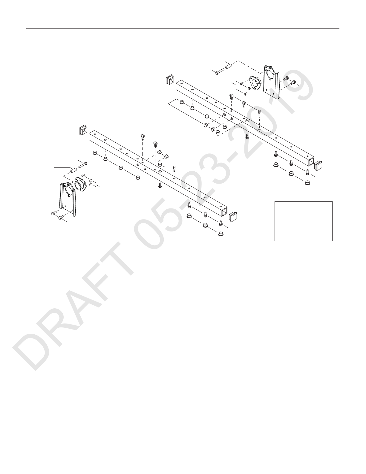
12.9 Main Bars
lbf·Ō
DRAFT 05-23-2019
4.5 lbf·Ō
†
(6 N·m)
4.5 lbf·Ō
††
(6 N·m)
1 lbf·Ō
(1.5 N·m)
TORQUE REFERENCES
MAIN BARS
1
†
1 lbf·Ō
(1.5 N·m)
††
†
†
Loctite 243
Blue Threadlocker
9 lbf·Ō
(12 N·m)
9 lbf·Ō
(12 N·m)
†
†
(1.5 N·m)
4.5 lbf·Ō
(6 N·m)
†
9 lbf·Ō
(12 N·m)
††
†
9 lbf·Ō
(12 N·m)
†
Loctite 2701
Green Threadlocker
79
Page 84
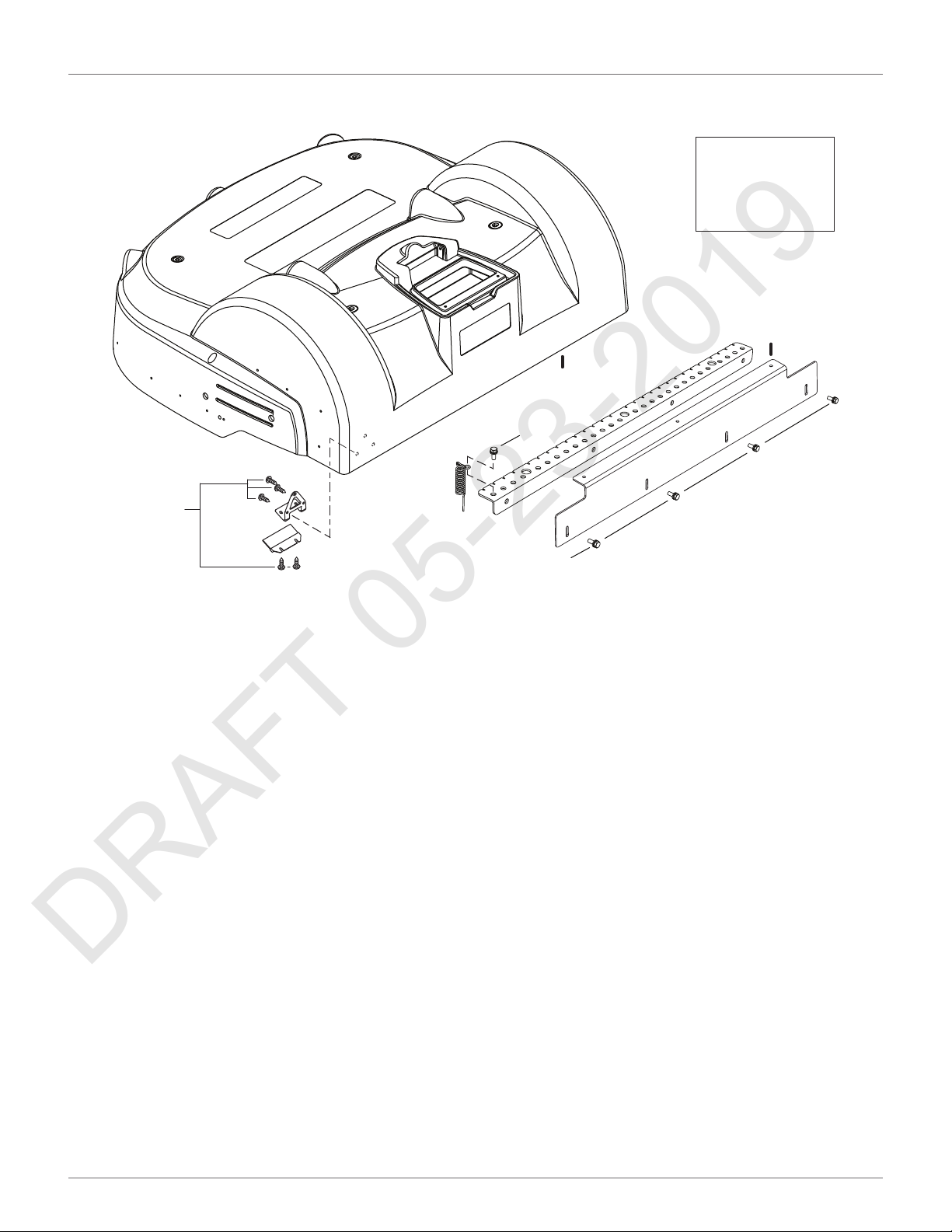
TORQUE REFERENCES
DRAFT 05-23-2019
ACCESSORIES
12.10 Accessories
5 lbf·Ō
(7 N·m)
†
Loctite 243
Blue Threadlocker
††
Loctite 2701
Green Threadlocker
A
A
†
4.5 lbf·Ō
(6 N·m)
9 lbf·Ō
(12 N·m)
†
80
Page 85
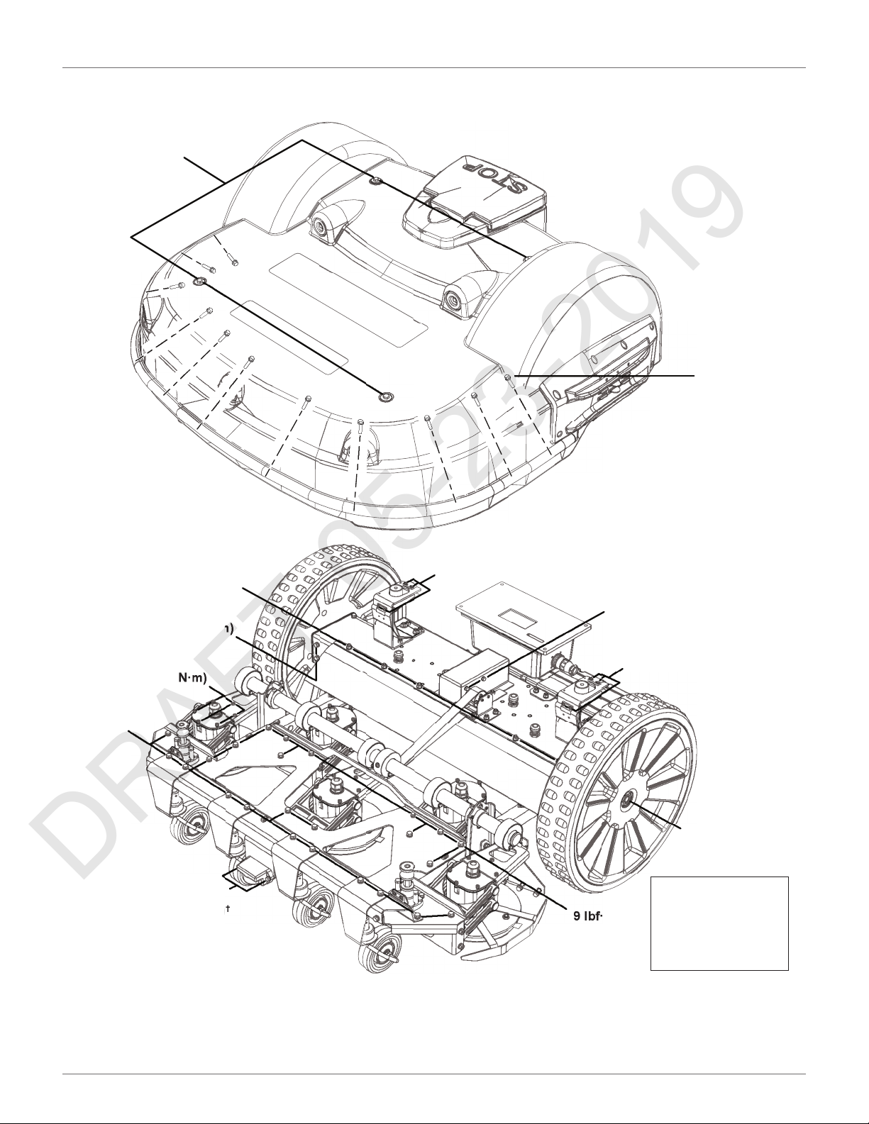
12.11 Cover and Chassis
DRAFT 05-23-2019
11 lbfÂft
(15 NÂP
TORQUE REFERENCES
COVER AND CHASSIS
5 lbfÂft
(7 NÂP
9 lbfÂft
(12 NÂP
2.25 lbfÂft
(3 NÂP
11 lbfÂft
(15 NÂP
1 lbfÂft
(1.5 NÂP
9 lbfÂft
(12 NÂP
1 lbfÂft
(1.5 NÂP
†
†
4.5 lbfÂft
(6 NÂP
9 lbfÂft
(12 NÂP
†
1 lbfÂft
(1.5 NÂP
†
48 lbfÂft
(65 NÂP
†
Loctite 243
Blue Threadlocker
††
Loctite 2701
Green Threadlocker
†
A - Rear View
B - Bottom View
81
Page 86
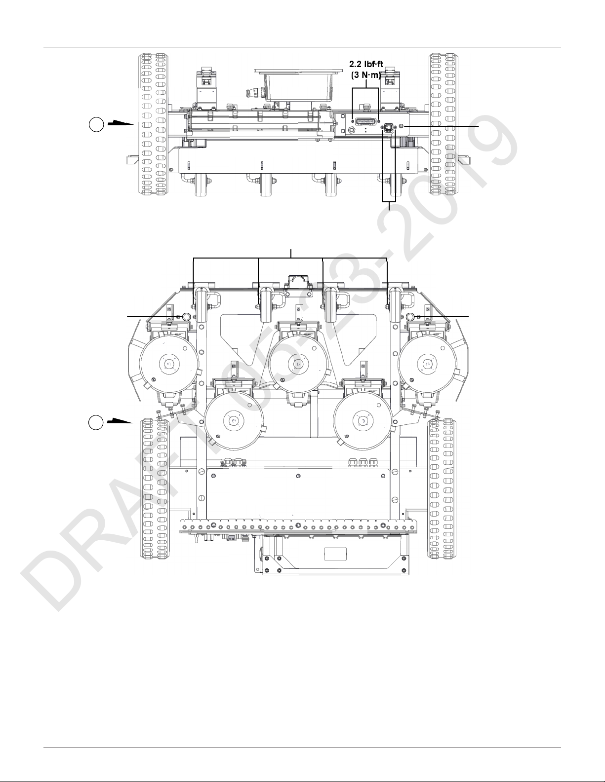
TORQUE REFERENCES
DRAFT 05-23-2019
COVER AND CHASSIS
2.2 lbfÂft
(3 NÂP
A
4.5 lbfÂft
(6 NÂP
7.5 lbfÂft
(10 NÂP
2.2 lbfÂft
(3 NÂP
2.2 lbfÂft
(3 NÂP
4.5 lbfÂft
(6 NÂP
B
82
Page 87

GEAR MOTOR, CUTTING HEAD, AND FRONT WHEEL
DRAFT 05-23-2019
12.12 Gear Motor, Cutting Head, and Front Wheel
A - Gear motor assembly.
B - Cutting head assembly.
C - Front wheel assembly.
A
TORQUE REFERENCES
4.5 lbf·Ō
(6 N·m)
4.5 lbf·Ō
(6 N·m)
2.2 lbf·Ō
(3 N·m)
B
4.5 lbf·Ō
(6 N·m)
1.5 lbf·Ō
(2 N·m)
†
†
†
†
C
9 lbf·Ō
(12 N·m)
1.0 lbf·Ō
1.5 lbf·Ō
(2 N·m)
(1.5 N·m)
7.5 lbf·Ō
(10 N·m)
†
Loctite 243
Blue Threadlocker
††
Loctite 2701
Green Threadlocker
83
Page 88

SPECIFICATIONS
DRAFT 05-23-2019
CAPACITY
13 Specifications
13.1 Capacity
Recommended mowable
1
area
Number of sports fields per
robot
Mowing width 41 in. (1033 mm)
Speed 2.2 mph (3.6 km/h)
Maximum slope 30%
1
Valid for a lawn that is rectangular, flat, without obstacles, with fertilizer and watering, being mowed
24 hours per day, seven days per week.
13.2 Cutting
Number of cutting heads 5
Number of cutting
blades
Low cut (minimum) 0.9 in. (22 mm)
High cut (maximum) 3.4 in. (100 mm)
Adjustment of cutting
heads
6 acres (20,000 m2)
1-2
15
Electronic
13.4 Weight and Dimensions
Weight 156.5 lbs. (71 kg)
Length 43.7 in. (1110 mm)
Width 50.3 in. (1278 mm)
Height 20.3 in. (466 mm)
13.5 Software and Monitoring
Security PIN code Yes
GPS positioning
APP robot management
Standard
13.6 Intelligence
Sonar detection of
obstacle
(height and diameter)
Adaptive cut
Return to station via GPS
Multiple starting zone
Multi field (optional)
Multi robot
Height 15.7 in. (400 mm)
Diameter 2.0 in. (50 mm)
In a future release
Maximum noise level <70 dB(A)
13.7 Safety
Lift sensors Yes
13.3 Battery
Reverse sensors No
Type Lithium-ion
Nominal Voltage 25.6 V
Nominal Capacity 19.2 Ah
Standard charge voltage 29.2 V
Maximum charge
current
Energy 491.5 Wh
Working temperature
range
Time to fully charge
(minimum)
Average mowing time
per charge
Average annual
consumption
19.2 A
Between -4 °F and 140 °F
(-20 °C and 60 °C)
80 minutes
110 minutes
830 kWh
Bumper Electronic
Deflectors on the cutting head Exterior
84
Page 89
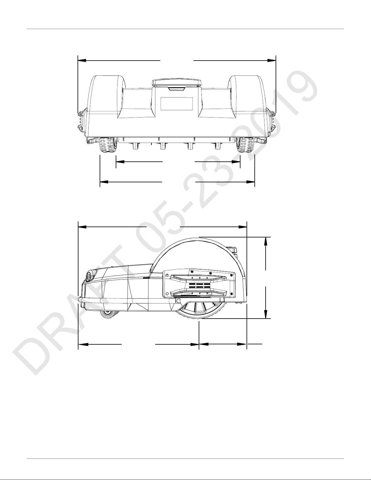
13.8 Dimensions
DRAFT 05-23-2019
SPECIFICATIONS
DIMENSIONS
50.3 in.
(1278 mm)
39.1 in.
(993 mm)
39.4 in.
(1000 mm)
(1110 mm)
31.6 in.
(804 mm)
43.7 in.
20.3 in.
(515 mm)
12.0 in.
(306 mm)
85
Page 90

ECHO Incorporated
DRAFT 05-23-2019
400 Oakwood Road
Lake Zurich, IL 60047
1-800-392-0329
www.echorobotics.com
 Loading...