

Page 1
Tiller/Cultivator
Operator's Manual
MODEL TC-210
Serial Number 05001001 - 05999999
TILLER/CULTIVATOR
OPERATOR'S MANUAL
1
W ARNING DANGER
Read rules for safe operation and instructions carefully. ECHO provides an Operator's
Manual, which must be read and understood for proper and safe operation.
X7504082800 X750005130
01/03
Page 2
2
INTRODUCTION
Welcome to the ECHO family. This ECHO product was designed and manufactured to provide
long life and on-the-job-dependability. Read and understand this manual. You will find it easy to use and
full of helpful operating tips and SAFETY messages.
THE OPERATOR'S MANUAL
Read and understand this manual before operation. Keep it in a safe
place for future reference. It contains specifications and information for
operation, starting, stopping, maintenance, storage and assembly
specific to this product.
TABLE OF CONTENTS
Introduction .............................................................. 2
- The Operator's Manual ...................................... 2
Manual Safety Symbols and Important Information. 3
Safety ......................................................................... 3
- Decals.................................................................. 3
- International Symbols .........................................4
Safety Instructions ....................................................4
- Personal Condition and Safety Equipment................ 4
- Extended Operation/Extreme Conditions .................. 5
- Equipment ................................................................. 5
- Safe Operation ........................................................... 6
Emission Control ................................................................ 6
Description ................................................................7
- Contents..............................................................7
Specifications.............................................................9
Assembly ................................................................. 10
Pre-Operation ........................................................... 11
- Fuel ................................................................... 11
Operation ................................................................. 12
- Starting Cold Engine ......................................... 1 2
- Starting Warm Engine ....................................... 1 3
- Stopping Engine ................................................ 13
- Tilling/Cultivating .............................................14
CopyRight© 2003 By Echo, Incorporated
All Rights Reserved.
Maintenance ............................................................ 15
- Skill Levels ........................................................ 15
- Maintenance Intervals ...................................... 15
- Air Filter ............................................................16
- Fuel Filter .......................................................... 16
- Spark Plug ......................................................... 1 7
- Cooling System Cleaning .................................. 17
- Exhaust System .................................................18
- Carburetor Adjustment ..................................... 1 9
- Lubrication ........................................................ 20
- Tine Removal/Cleaning/Installation ..................20
Troubleshooting ...................................................... 21
Storage..................................................................... 22
Servicing Information...............................................24
- Parts .................................................................. 24
- Service............................................................... 24
- ECHO Consumer Product Support ....................2 4
- Warranty Card ................................................... 24
- Additional or Replacement Manuals ................. 24
Specifications, descriptions and illustrative material in
this literature are as accurate as known at the time of
publication, but are subject to change without notice.
Illustrations may include optional equipment and
accessories, and may not include all standard equipment.
Page 3
SAFETY SYMBOLS AND IMPORTANT INFORMATION
Throughout this manual and on the product itself, you will find safety
alerts and helpful, information messages preceded by symbols or key
words. The following is an explanation of those symbols and key words
and what they mean to you.
TILLER/CULTIVATOR
OPERATOR'S MANUAL
IMPORTANT
3
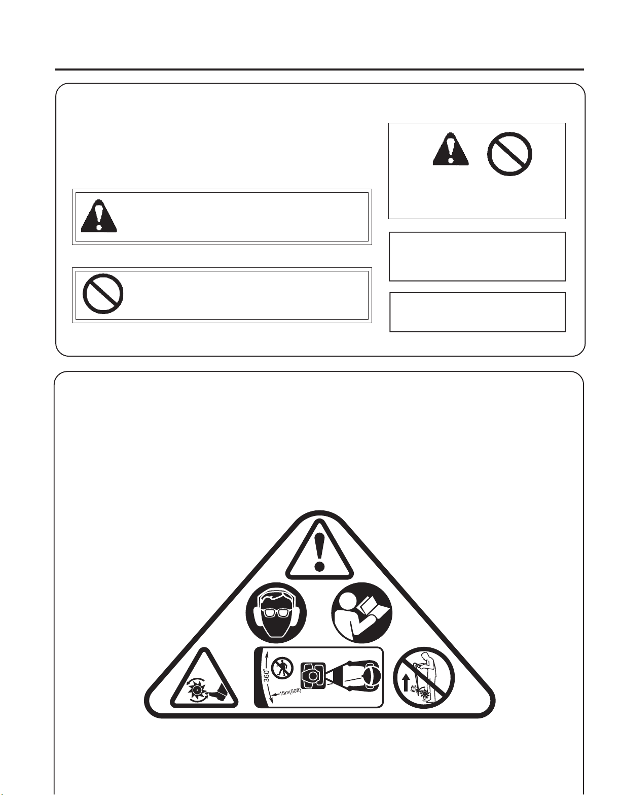
This symbol accompanied by the words WARNING
andDANGER calls attention to an act or condition that
can lead to serious personal injury to operator and
bystanders.
The circle with the slash symbol means whatever is
shown within the circle is prohibited.
IMPORTANT The enclosed
message provides information
necessary for the protection of the
unit.
NOTE This enclosed message
provides tips for use, care and
maintenance of the unit.
NOTE
SAFETY
DECALS
Locate these safety decals on your unit. The complete unit illustration found in the "DESCRIPTION" section, will help
you locate them. Make sure the decals are legible and that you understand and follow the instructions on them. If a
decal cannot be read, a new one can be ordered from your ECHO dealer. See PARTS ORDERING instructions for specific
information.
P/N X505001210
TINE GUARD
Page 4
4
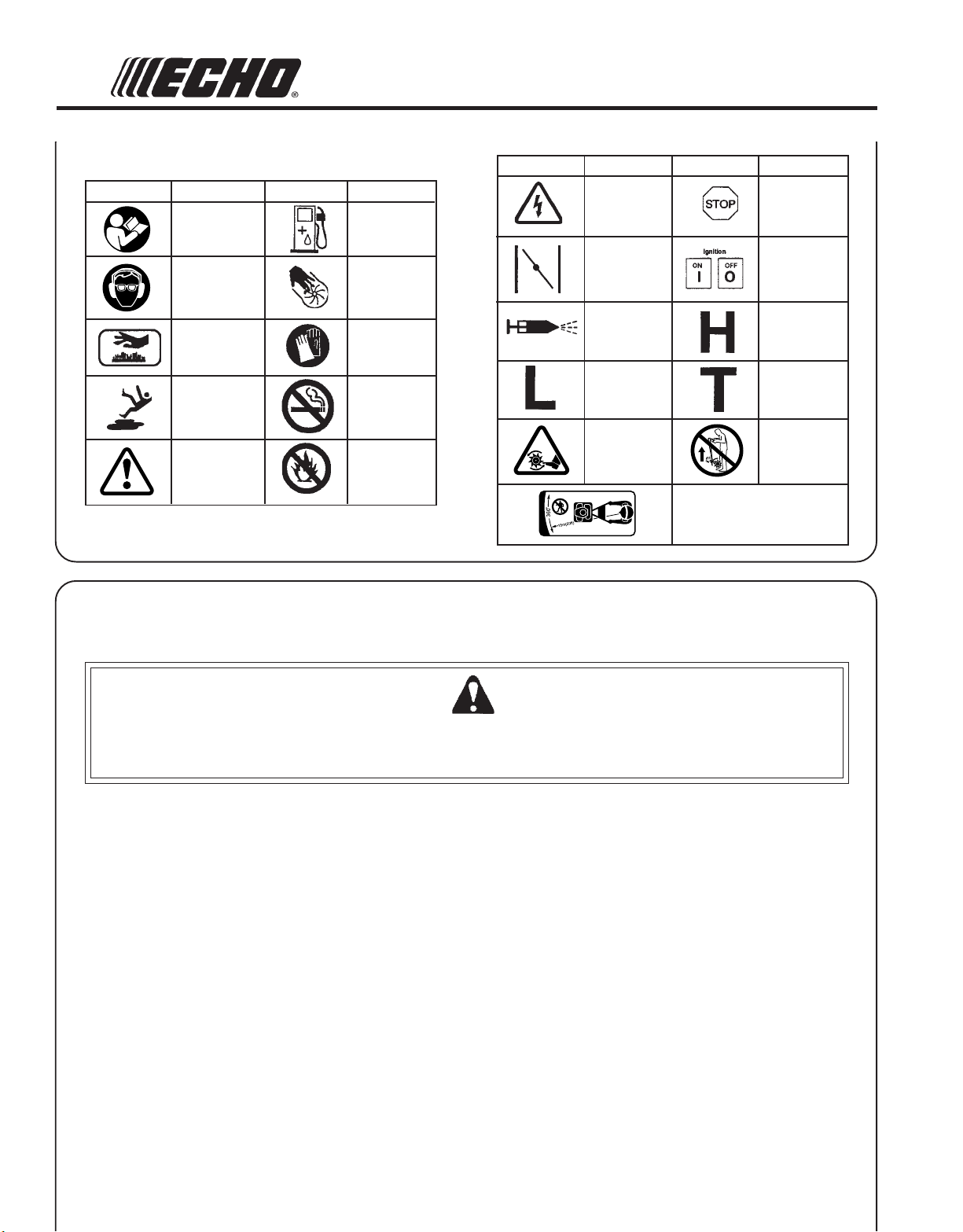
INTERNA TIONAL SYMBOLS
Symbol form/shape
Symbol
description/application
Read and understand
Operator's Manual.
Wear eye, hea and
hearing protection
Hot
Surface
Wear slip
resistant foot
wear.
Safety/Alert
Symbol form/shape
Symbol
description/application
Fuel and oil mixture
Finger Severing
Wear hand
protection. Use
two handed.
DO NOT smoke
near fuel.
DO NOT allow
flames or sparks
near fuel.
Symbol form/shape
Symbol
description/application
Avoid all power
lines. This unit is
not insulated
against electrical
current.
Engine choke
control.
Primer
bulb
Carburetor adjustment
- Low speed mixture
Keep away from
rotating tines.
Symbol form/shape
Keep bystanders a minimum of
15m (50 ft.) away while operating
Symbol
description/application
Emergency stop
Ignition
ON/OFF
Carburetor adjustment
- High speed mixture
Carburetor adjustment
- Idle speed
Carry unit with
carry handle.
unit.
SAFETY INSTRUCTION
PERSONAL
Tiller/Cultivator users risk injury to themselves and others if the tiller/cultivator is used improperly and or safety
precautions are not followed. Proper clothing and safety gear must be worn when operating a tiller/cultivator. Failure
to do so can result in serious injury.
Physical Condition --
Your judgment and physical dexterity may not be good:
- if you are sick,
- if you are taking medication,
- if you have taken alcohol or drugs.
Operate unit only if you are physically and mentally well.
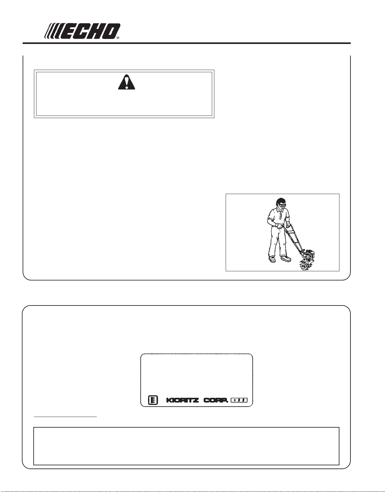
Eye Protection --
Wear Eye protection that meet ANSI Z87.1 or CE requirements whenever you operate the tiller/cultivator.
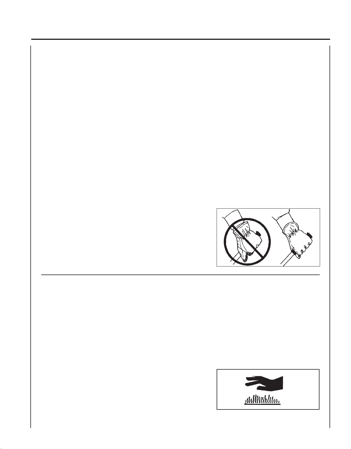
Hand Protection --
Wear no-slip, heavy duty work gloves in improve your
grip on the Tiller/Cultivator handles. Gloves also reduce
the transmission of machine vibration to your hands.
Hearing Protection --
ECHO recommends wearing hearing protection whenever
unit is used.
CONDITION AND SAFETY EQUIPMENT
W ARNING DANGER
Proper Clothing --
Wear snug fitting, durable clothing;
- Pants should have long legs, shirts with long sleeves.
- Wear hair covering to contain long hair.
- DO NOT WEAR SHORTS,
- DO NOT WEAR TIES, SCARFS, JEWELRY.
Wear sturdy work shoes with non-skid soles;
- DO NOT WEAR OPEN TOED SHOES,
- DO NOT OPERATE UNIT BAREFOOTED.
Wear no-slip, heavy duty work gloves.
Hot Humid Weather --
Heavy protective clothing can increase operator fatigue
which may lead to heat stroke. Schedule heavy work for
early morning or late afternoon hours when temperatures
are cooler.
Page 5
EXTENDED OPERATION/EXTREME CONDITIONS
Vibration and Cold --
It is believed that a condition called Raynaud’s Phenomenon, which
affects the fingers of certain individuals may be brought about by
exposure to vibration and cold. Exposure to vibration and cold may
cause tingling and burning sensations followed by loss of color and
numbness in the fingers. The following precautions are strongly
recommended because the minimum exposure which might trigger the
ailment is unknown.
• Keep your body warm, especially the head, neck, feet, ankles, hands
and wrists.
• Maintain good blood circulation by performing vigorous arm
exercises during frequent work breaks and also by not smoking.
• Limit the hours of operation. Try to fill each day with jobs where
operating the trimmer or other hand-held power equipment is not
required.
• If you experience discomfort, redness and swelling of the fingers
followed by whitening and loss of feeling, consult your physician
before further exposing yourself to cold and vibration.
Repetitive Stress Injuries --
It is believed that overusing the muscles and tendons of the fingers,
hands, arms and shoulders may cause soreness, swelling, numbness,
weakness and extreme pain in those areas. Certain repetitive hand
activities may put you at a high risk for developing a Repetitive Stress
Injury (RSI). An extreme RSI condition is Carpal Tunnel Syndrome
(CTS), which could occur when your wrist swells and squeezes a vital
nerve that runs through the area. Some believe that prolonged exposure
to vibration may contribute to CTS. CTS can cause severe pain for
months or even years.
TILLER/CULTIVATOR
OPERATOR'S MANUAL
To reduce the risk of RSI/CTS, do the
following:
• Avoid using your wrist in a bent,
extended or twisted position. Instead try
to maintain a straight wrist position.
Also, when grasping, use your whole
hand, not just the thumb and index finger.
• Take periodic breaks to minimize repetition and rest your hands.
• Reduce the speed & force in which you
do the repetitive movement.
• Do exercises to strengthen the hand and
arm muscles.
• Immediately stop using all power
equipment and consult a doctor if you
feel tingling, numbness or pain in the
fingers, hands, wrists or arms. The
sooner RSI/CTS is diagnosed, the more
likely permanent nerve and muscle
damage can be prevented.
5
EQUIPMENT
Before operation a complete check of the unit must be performed;
• Check unit for loose/missing nuts, bolts and screws. Tighten and/or
replace as needed.
• Inspect fuel lines, tank and area around carburetor for fuel leaks. DO
NOT operate unit if leaks are found.
• Inspect shield for damage and ensure that the shield is securely in
place. Replace if shield is damaged or missing.
• Check that the tines are firmly attached and in safe operating condition.
• Keep exhaust area clear of flammable debris. Avoid contact during
and immediately after operation.
Page 6
6
SAFE OPERATION
W ARNING DANGER
Do not operate this product indoors or in inadequately ventilated
areas. Engine exhaust contains poisonous emissions and can
cause serious injury or death.
TO AVOID INJURY :
• Read and understand the OPERATOR’S MANUAL.
• Know location and functions of all controls.
• Keep all Safety devices and shields in place.
• Never allow children or uninstructed adults to operate the unit
• Shut off engine before unclogging tines or making repairs.
• Keep bystanders and animals a minimum of 15m (50 ft.) away while
operating unit.
• Keep away from rotating parts.
• Always wear eye and hearing protection while operating machine.
• Do not hold or carry unit in a manner that will permit tines to contact
body parts or clothing.
• Refer to Operator’s Manual for correct carrying instructions.
• BEFORE OPERATION, refer to your Operator’s Manual for proper
operating techniques.
• If you require a replacement manual, contact ECHO, Inc. , 400
Oakwood Road, Lake Zurich, IL 60047.
• Always empty the fuel tank before carrying unit in a car or truck. To
avoid damage to engine parts always lay unit on its muffler side.
• Keep away from rotating tines. Rotating
tines cause injury.
• ALWAYS STOP THE ENGINE IF A TINE
JAM OCCURS.
• Never attempt removing the object causing
the jam if the engine is running.
• Physical injury can occur if a tine jam is
removed and the tine suddenly starts.
EMISSION CONTROL
EPA Phase 2
The emission control system for these engines are EM (Engine Modification).
ENGINE FAMILY : 3EHXS.0214ED DISPLACEMENT : 21.2cc
EMISSION COMPLIANCE PERIOD: 300 HOURS
THIS ENGINE MEETS U.S. EPA PH 2 EMISSION
REGULATIONS FOR SMALL NONROAD ENGINES. REFER
TO OWNER'S MANUAL FOR MAINTENANCE SPECIFICATIONS AND ADJUSTMENTS.
Emission Control Label (located on Engine) (EXAMPLE ONLY, information on label varies by FAMILY).
PRODUCT EMISSION DURABILITY
The 300 hour emission durability compliance period is the time span selected by the manufacturer certifying the
engine emissions output meets applicable emissions regulations, provided that approved maintenance procedures are
followed as listed in the Maintenance Section of this manual.
IMPORTANT ENGINE INFORMA TION
Page 7
TILLER/CULTIVATOR
OPERATOR'S MANUAL
DESCRIPTION
The ECHO product you purchased has been factory pre-assembled for your convenience. Due to packaging restrictions
some assembly is required.
After opening the carton, check for damage. Immediately notify your retailer or ECHO Dealer of damaged or missing
parts. Use the contents list to check for missing parts.
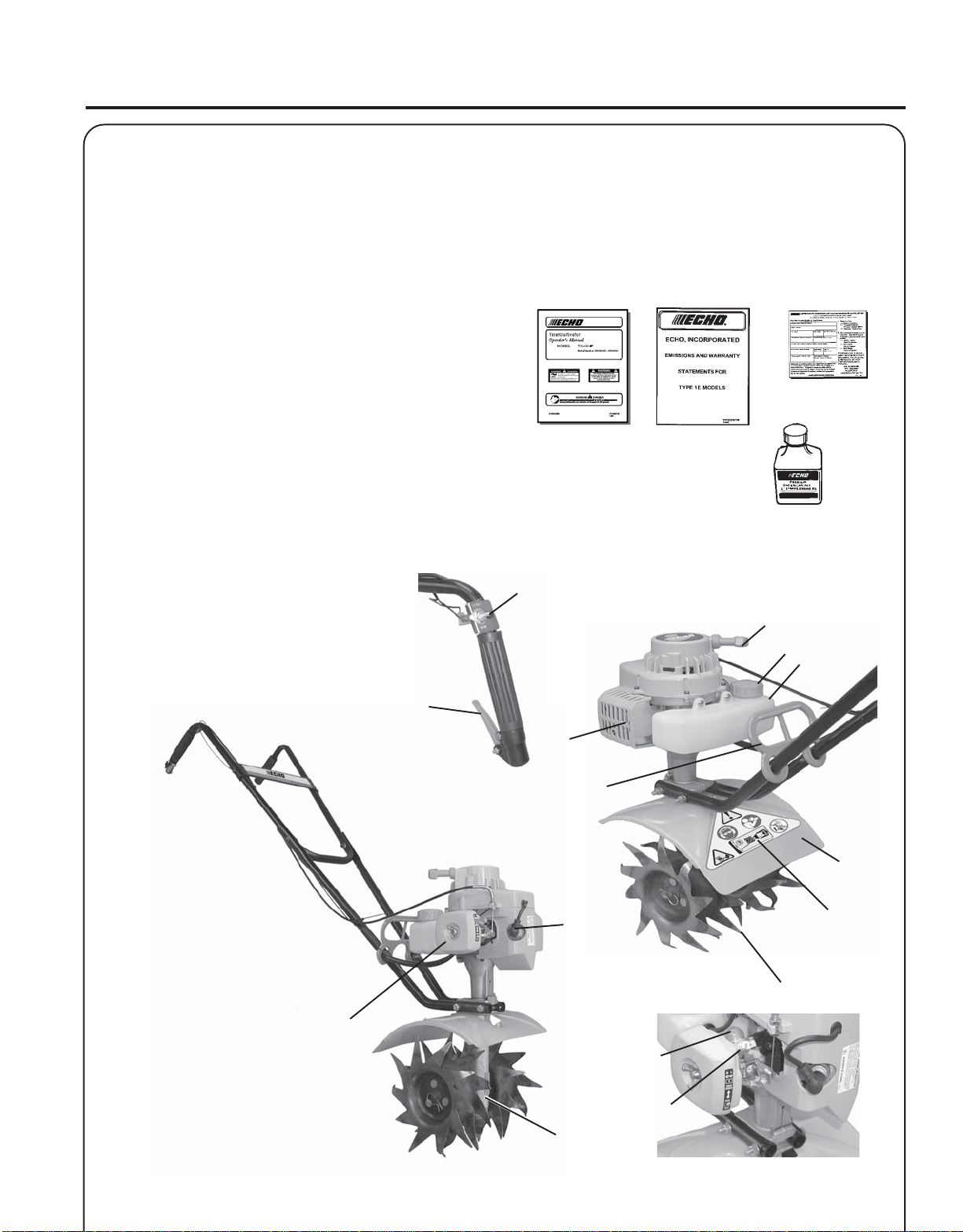
CONTENTS
____ 1 - Power Head & Shield Assembly
____ 1 - Upp e r H a n dle Assembly
____ 1 - Left Lower Handle
____ 1 - Right Lower Handle
____ 2 - Lower Handle Mounting Eye Plates
____ 1 - 1/4 in. x 3 in. Hex Head Shoulder Bolt
____ 1 - 1/4 in. x 3-1/4 in. Hex Head Shoulder Bolt
____ 2 - 1/4 in. Lock Washers
____ 2 - 1/4 in. Lock Nuts
____ 1 - Plastic Carry Handle
____ 1 - Cable Tie
____ 1 - Operator's Manual
____ 1 - Warranty Card & Limited
Warranty Statement
____ 2 - 10mm x 30mm Carriage Bolt
____ 2 - 10mm nut
____ 2 - 10mm Lock Washer
____ 1 - Bottle 2-Cycle Engine Oil
1
8
9
10
7
2
15
14
11
3
13
7
4
5
6
12
Page 8

8
1. STOP SWITCH - Toggle Switch mounted on upper right handle. Move switch forward to "Start" position to run,
back to "Stop" position to stop unit.
2. THROTTLE TRIGGER - Spring loaded to return to idle when released. When accelerating, pull trigger gradually for
best operating technique. DO NOT hold trigger when starting.
3. SPARK PLUG -
4. PRIMER BULB - Pumping primer bulb before starting engine draws fresh fuel from the fuel tank priming the
carburetor for starting. Pump primer bulb until fuel is visible and flows freely in the clear fuel tank return line. Pump
bulb an additional 4 or 5 times.
5. CHOKE - The choke control is located on the side of the air filter case. Move choke to "COLD START" to close the
choke for cold starting. Move choke to "RUN" position to open choke.
6. GEAR BOX - Houses gears for driving tines.
7. AIR CLEANER - Contains replaceable filter element.
8.
RECOIL STARTER HANDLE/ROPE - Pull recoil starter handle/rope using light pulling force, approximately 2/3
(2 ft.) of rope length. Two (2) to Six (6) pulls are required to properly tension starter spring prior to automatic engine
engagement. DO NOT let handle snap back or damage to unit will occur.
9. FUEL TANK CAP - Cover and seals fuel tank opening.
10. FUEL TANK - Contains fuel and fuel filter.
11. TINE GUARD - Used to help deflect debris away from operator and reduce accidental contact with tines.
12. SAFETY DECAL - Safety precautions - See Page 3.
Provides spark to ignite fuel mixture.
13. TINES - Special 10-tooth tines are reversible for tilling or cultivating, removable for cleaning.
14. PLASTIC CARRYING HANDLE - Use to lift and carry unit.
15. SPARK ARRESTOR - CATALYTIC MUFFLER / MUFFLER -The muffler or catalytic muffler controls exhaust noise
and emission. The spark arrestor screen prevents hot, glowing particles of carbon from leaving the muffler. Keep
exhaust area clear of flammable debris.
Page 9

TILLER/CULTIVATOR
OPERATOR'S MANUAL
SPECIFICATIONS
MODEL -----------------------------------------------------TC-210
Length------------------------------------------------------- 1130 mm (44.48 in.)
Width--------------------------------------------------------340 mm (13.36 in.)
Height -------------------------------------------------------1010 mm (39.76 in.)
Weight (dry) w/Tines -------------------------------------9.08 kg (20.0 lb.)
Engine Type ------------------------------------------------ Air cooled, two-stroke, single cylinder gasoline engine
Bore----------------------------------------------------------32.2 mm (1.268 in.)
Stroke--------------------------------------------------------26.0 mm (1.04 in.)
Displacement -----------------------------------------------21.2 cc (1.29 cu. in.)
Exhaust ------------------------------------------------------Spark Arrestor Muffler
Carburetor --------------------------------------------------Zama diaphragm model C1U w/primer bulb
Ignition System -------------------------------------------- Flywheel magneto, capacitor discharge ignition type
Spark Plug --------------------------------------------------NGK BPM-8Y Gap 0.65 mm (0.026 in.)
Fuel ----------------------------------------------------------Mixed (Gasoline and Two-stroke Oil)
Fuel/Oil Ratio -----------------------------------------------50:1 ECHO High Performance, two-stroke air cooled engine oil
Gasoline ----------------------------------------------------- 89 Octane unleaded. DO NOT use fuel containing methyl alcohol,
more than 10% ethyl alcohol or 15% MTBE.
O il ------------------------------------------------------------ 50:1 ECHO High Performance, two-stroke air cooled engine oil
Fuel Tank Capacity ----------------------------------------0.5 lit. (17.0 US fl. oz.)
Recoil Starter System -------------------------------------Clutch ------------------------------------------------------- Centrifugal Type
Gear Case --------------------------------------------------- Worm Gear Type (42:1 Ratio)
Tines -------------------------------------------------------- Special 10 Tooth Design
Tilling/Cultivating ----------------------------------------- 229 mm (9 in.) x 15-20 mm (6-8 in.)
Tine Diameter-----------------------------------------------229 mm (9 in.)
Idle Speed---------------------------------------------------2,500 - 3,100 RPM
Wide Open Throttle Speed (W.O.T.) --------------------10,000 - 10,500 RPM
- Start Automatic Rewind Starter
9
Page 10

10
ASSEMBLY
Tools Required: (2) 7/16 in. Wrenches
1. Support powerhead assembly upright on tines. Place top handle
assembly to rear.
NOTE
Make sure inside curves at handle ends are facing each other.
2 . Loosely assemble lower handles using short 1/4 in. x 3 in. long hex
head shoulder bolt (A), eye plates (B), lockwasher (C), and locknut
(D) in front handle end mounting hole as shown.
A
C,D
3. Slide lower handle assembly under power head and throttle
linkage/ignition wires, and position in mounting groove.
4 . Assemble using long 1/4 in. x 3-1/4 in. hex head shoulder bolt (E),
eye plate (B), lockwasher (C), and locknut (D) in rear handle
mounting holes. DO NOT TIGHTEN BOLTS.
5. Slide plastic carry handle onto lower handle tubes.
6 . Remove (2) 10mm x 30mm carriage bolts (F), (2) lockwashers (G),
and (2) nuts (H) from top handle assembly.
B
C,D
B
E
7. Place top handle assembly between lower handles, align mounting
holes and install (2) 10mm x 30mm carriage bolts (F), (2)
lockwashers (G), and (2) nuts (H). Carriage bolts must be installed
from the outside through square holes in the lower handle, then
through upper handle tube.
8. Securely tighten lower handle bolts first, then the upper handle
bolts.
9 . Secure throttle linkage and stop switch lead midway on right lower
handle with cable tie.
F
G, H
G, H
F
Page 11

PRE-OPERATION
FUEL
Fuel Requirements
TILLER/CULTIVATOR
OPERATOR'S MANUAL
11
Gasoline - Use 89 Octane [R+M/2] (mid grade or higher) gasoline known
to be good quality. Gasoline may contain up to 15% MTBE (methyl
tertiary-butyl ether). Gasohol containing methyl (wood) alcohol is NOT
approved.
Two Stroke Oil - A two-stroke engine oil meeting ISO-L-EGD (ISO/CD
13738) and J.A.S.O. FC Standards, must be used. Echo brand Premium
50:1 oil meets these standards. Engine problems due to inadequate
lubrication caused by failure to use an ISO-L-EGD and J.A.S.O. FC
certified oil, such as Echo Premium 50:1 Two-stroke Oil, will void the
two-stroke engine warranty. (Emission related parts only are covered
for two years, regardless of two-stroke oil used, per the statement listed
in the Emission Defect Warranty Explanation.)
IMPORTANT
Echo Premium 2-Stroke Oil may be mixed at 50:1 ratio for application in all Echo engines sold in the past regardless of ratio
specified in those manuals.
Mixing Instructions
1 . Fill an approved fuel container with half of the required amount of
gasoline.
2 . Add proper amount of 2-stroke oil to gasoline.
3 . Close container and shake to mix oil with gasoline.
4 . Add remaining gasoline and remix.
5 . Install fuel container cap and wipe any spilled fuel from container
and surrounding area.
Handling Fuel
IMPORTANT
Spilled fuel is a leading cause of
hydrocarbon emissions. Some states
may require the use of automatic fuel
shut-off containers to reduce fuel
spillage. Contact your ECHO dealer
for ordering information.
After Refueling;
• Wipe any spilled fuel from the unit.
• Move at least 3 m (10 ft.) from refueling
location before starting the engine.
After use;
• DO NOT store a unit with fuel in its tank.
Leaks can occur. Return unused fuel to an
approved fuel storage container.
Storage -
Fuel storage laws vary by locality. Contact
your local government for the laws affecting
your area. As a precaution, store fuel in an
approved, air tight container. Store in a well
ventilated, unoccupied building, away from
sparks and flames. Do not store fuel longer
than 30 days.
IMPORTANT
Stored fuel ages. Do not mix more fuel
than you expect to use in thirty (30)
days, ninety (90) days when a fuel
stabilizer is added.
W ARNING DANGER
Fuel is VERY flammable. Use extreme care when mixing, storing or
handling, or serious personal injury may result.
• Use an approved fuel container.
• DO NOT smoke near fuel.
• DO NOT allow flames or sparks near fuel.
• Fuel tanks/cans may be under pressure. Always loosen fuel caps
slowly allowing pressure to equalize.
• NEVER refuel a unit when the engine is HOT!
• NEVER refuel a unit with the engine running.
• DO NOT fill fuel tanks indoors. ALWAYS fill fuel tanks out
doors over bare ground.
• Securely tighten fuel cap after refueling.
• Inspect for fuel leakage. If fuel leakage is found, do not start or
operate unit until leakage is repaired.
IMPORTANT
Stored two-stroke fuel may separate.
ALWAYS shake fuel container thoroughly before each use.
Page 12

12
OPERATION
STARTING
COLD ENGINE
W ARNING DANGER
The tines should not move at idle. If tines move, readjust carburetor
according to "Carburetor Adjustment" instructions in this manual
or see your ECHO Dealer, otherwise serious personal injury may
result.
1. Stop Switch
Move Stop Switch (A) to "START" position.
2. Choke
Move choke (B) to "COLD START" position. Throttle must remain
at idle position for starting.
3. Primer
Pump primer bulb (C) until fuel is visible and flows freely in the
clear fuel tank return line. Pump bulb an additional 4 or 5 times.
A
C
B
NOTE
Energy is stored in the starter spring each time the handle/rope is
pulled. Generally two to six pulls, using light pulling forces, will
store enough energy to engage the starter and spin the engine. Do
not pull the rope out to end stop.
4. Recoil Starter
Gently pull recoil starter handle/rope (D) until engine fires or 2 to 3
engine engagements.
5. Choke
After engine fires or 2 to 3 engine engagements, move choke (B) to
RUN (open) position.
6. Recoil Starter
Pull recoil starter rope until engine starts.
NOTE
If engine does not start with choke in “Run” position after 5 engine
engagements, repeat instructions.
7 . After engine warm up, gradually depress throttle trigger to increase
engine RPM to operating speed.
Page 13

STARTING WARM ENGINE
The starting procedure is the same as cold start except DO NOT close
the choke (B).
NOTE
If engine does not start after 5 engine engagements, use Cold Start
Procedure.
TILLER/CULTIVATOR
OPERATOR'S MANUAL
13
1. Stop Switch
Move Stop Switch (A) to START position. Throttle trigger must
remain at idle position for starting.
2. Primer
Pump primer bulb (C) until fuel is visible and flows freely in the
clear fuel tank return line. Pump bulb an additional 4 or 5 times.
3. Choke
Be certain choke (B) is in "RUN" position.
4. Recoil Starter
Pull recoil starter rope until engine starts.
A
C
B
STOPPING ENGINE
1. Throttle Trigger
Release throttle and allow engine to return to idle before shutting
engine off.
2. Stop Switch
Move stop switch to "STOP" position (A).
W ARNING DANGER
If engine does not stop when stop switch is moved to STOP
position, close choke - COLD START position - to stall engine.
Have your ECHO dealer repair stop switch before using tiller/
cultivator again.
A
Page 14

14
TILLING/CULTIVATING
W ARNING DANGER
Do not operate this unit indoors or in inadequately ventilated
areas.
• Carry unit to tilling/cultivating area using plastic carry handle and
upper handle. Avoid contact with tines or hot engine parts.
• Check the area to be tilled or cultivated. Look for any hazards and
obstructions that could contribute to unsafe conditions.
• Remove all rocks, debris, and other materials that could become
jammed in the tines.
• Do not till or cultivate in areas where there may be hidden hazards,
such as sprinkler heads and pipes, buried power cables or gas lines,
or other similar hazards.
• Start the unit as shown in “Starting” instructions.
• Hold unit securely, using both hands to grip hand grips.
• Depress throttle trigger gradually to begin operation.
• Release throttle trigger to stop tines.
• Allow engine to return to idle, and move switch to “Stop” position to
stop engine.
TILLING – Recommended tilling depth is 6 – 8 inches
Install Tines with individual tines angled forward, toward front of unit.
(See Tine Removal/Cleaning/Installation, page 20)
• Use a forward/backward motion to till soil. Allow tines to dig into
soil, then pull unit back to break up and pulverize clumps. Tilling
depth is controlled by the number of times the forward/backward
motion is used in an area.
• Controlling tilling depth :
• Shallow tilling: Move tiller over soil surface quickly. Tines should be
in cultivating position.
• Deeper tilling: Move tiller over soil slowly. Allow tiller to work the
same area until desired depth is reached.
• Big Weeds/Tough Roots: Rock tiller back and forth over tough spot
until the tines slice through the roots or weeds.
• Digging Holes: Hold tiller in place, and allow tines to dig down into
the soil. Allow tines to dig approximately 6 – 8 inches deep, then lift
unit up and out. Remove loose soil with shovel or rake. Resume
digging with rotating tiller tines until desired depth is reached.
CULTIVATING – Recommended cultivating depth is 2 – 3 inches
Install Tines with individual tines angled rearward, toward the operator.
(See Tine Removal/Cleaning/Installation, page 20)
Allow unit to move forward slowly. Pull unit back to cut vegetation and
cultivate soil to desired depth. Repeat forward/backward motion as
needed.
TILLING
CULTIVATING
Page 15

TILLER/CULTIVATOR
OPERATOR'S MANUAL
15
MAINTENANCE
Your ECHO tiller/cultivator is designed to provide many hours of trouble free service. Regular scheduled maintenance will
help your tiller/cultivator achieve that goal. If you are unsure or are not equipped with the necessary tools, you may want
to take your unit to an ECHO Service Dealer for maintenance. To help you decide whether you want to DO-IT-YOURSELF or have the ECHO Dealer do it, each maintenance task has been graded. If the task is not listed, see your ECHO
dealer for repairs.
SKILL LEVEL
Level 1 = Easy to do. Most required tools come with unit.
Level 2 = Moderate difficulty. Some specialized tools may be required.
Level 3 = Experience required. Specialized tools are required. ECHO recommends
that the unit be returned to your ECHO Dealer for service.
ECHO offers REPOWERTM Maintenance Kits and Parts to make your maintenance job easier. Just below each task
heading are listed the various part numbers required for that task. See your ECHO dealer for these parts.
MAINTENACE INTERV ALS
/TNENOPMOC
METSYS
troPtsuahxErednilyCnobraceD/naelC/tcepsnI 3 C/I
retliFriAecalpeR/naelC/tcepsnI 1 C/I*R
ekohCnaelC/tcepsnI 2 C/I
retliFleuFecalpeR/tcepsnI 1 I*R
skael,metsySleuFecalpeR/tcepsnI 1 *I*I
metsySgnilooCnaelC/tcepsnI 2 C/I
rotserrAkrapSrelffuMecalpeR/tcepsnI 2 *I
gnisuoHraeGesaerG 2 )1(I
seniTnaelC/tcepsnI 1 C/I
ECNANETNIAM
ERUDECORP
D'QER
LLIKS
LEVEL
ROYLIAD
EROFEB
ESU
YREVE
LEUFER
serudecorPecnanetniaMflesruoY-tI-oD
3
SHTNOM
09RO
SRUOH
serudecorPecnanetniaMrelaeDohcEdednemmoceR
6
SHTNOM
072RO
SRUOH
YLRAEY
006
SRUOH
* ..noitcepsnignirudraewroegamadfognidnifehtnodesaberaecalperotsnoitadnemmocerllA
)1( OHCEylppA
epoRretratSlioceRnaelC/tcepsnI 1 *C/I
gulPkrapSnaelC/tcepsnI 2 C/I*R
stloB/stuN/swercSecalpeR/nethgiT/tcepsnI 1 *R/I
-ETONTNATROPMI deriuqerfoycneuqerfehtenimretedlliwecneirepxeruoydnaesulautcA.mumixameranwohsslavretniemiT
.ecnanetniam
MT
EBUL
®
SEDOCRETTELERUDECORPECNANETNIAM NAELC=C,ECALPER=R,TCEPSNI=I:
:SETONERUDECORPECNANETNIAM
.sruoh52yreve
Page 16

16
AIR FILTER
Level 1.
Tools required: 25-50mm (1-2 in.) medium bristle paint brush.
Parts required: 90008 REPOWER
1 . Close choke (Cold Start Position). This prevents dirt from entering
the carburetor throat when the air filter is removed. Brush accumulated dirt from the air cleaner area.
2 . Remove the air cleaner cover. Clean and inspect the element for
damage. If element is fuel soaked and very dirty, replace.
3 . If element can be cleaned and reused, be certain it:
-still seals the cavity in the air cleaner cover.
-is installed with the original side out.
NOTE
Carburetor adjustment may be needed after air filter cleaning/
replacement. See Carburetor Adjustment Section.
TM
AIR & FUEL FILTER KIT.
FUEL FILTER
Level 1.
Tools required: Fuel line hook. 200-250mm (8-10 in.) length of wire
with one end bent into a hook. Clean rag, funnel, and
an approved fuel container.
Parts required: 90008 REPOWERTM AIR & FUEL FILTER KIT
W ARNING DANGER
Fuel is VERY flammable. Use extreme care when mixing, storing or
handling, or serious personal injury may result.
1 . Use a clean rag to remove loose dirt from around fuel cap and
empty fuel tank.
2 . Use the “fuel line hook” to pull the fuel line and filter (A) from the
tank.
3 . Remove the filter (A) from the line and install the new filter.
A
Page 17

SPARK PLUG
Level 2.
Tools Required: Spark Plug socket wrench and screw driver, Feeler
gauge. Preferably a wire gauge.
Parts Required: REPOWERTM Tune-Up Kit P/N 90074
1 . Remove spark plug and check for fouling, worn and rounded center
electrode.
2 . Clean the plug or replace with a new one. DO NOT sand blast to
clean. Remaining sand will damage engine.
TILLER/CULTIVATOR
OPERATOR'S MANUAL
17
3. Adjust spark plug gap by bending outer electrode.
4 . Tighten spark plug to 145-155 kg/cm (125-135 in. lb.).
COOLING SYSTEM CLEANING
Level 2.
Tools required: Cross Head Screwdriver, 3mm Hex wrench, Pointed
Wood Stick, 25-50mm (1-2 in.) medium bristle
paint brush.
Parts Required: None.
IMPORTANT
To maintain proper engine operating temperatures, cooling air must
pass freely through the cylinder fin area. This flow of air carries
combustion heat away from the engine.
Overheating and engine seizure can occur when:
• Air intakes are blocked, preventing cooling air from reaching the
cylinder.
• Dust and grass build up on the outside of the cylinder. This build
up insulates the engine and prevents the heat from leaving.
0.65 mm
(0.026 in.)
Removal of cooling passage blockages or cleaning of cooling fins is
considered “Normal Maintenance.” Any failure attributed to lack of
maintenance is not warranted.
1. Disconnect spark plug lead. Remove spark plug and throttle cable
end from the carburetor swivel.
2 . Remove four screws from starter cover, lift the cover from the
engine and lay to the side.
NOTE
The throttle cable remains assembled to the cover.
Page 18

18
3 . Remove bottom left (A) and bottom right (B) screws from cylinder
cover.
4 . Carefully pull cylinder cover forward, disengaging muffler gasket
tabs and ignition lead, and lay aside.
5 . Use brush to remove dirt from cylinder fins.
IMPORTANT
DO NOT use a metal scraper to remove dirt from the cylinder fins.
6. Assemble components in reverse order.
NOTE
When installing the cylinder cover, be certain the muffler gasket
tabs are locked into the muffler grill slots and the stop switch lead is
seated in the relief notch.
Cylinder Exhaust Port
B
A
Level 3.
IMPORTANT
The cylinder exhaust port must be inspected and cleaned of excess
carbon every 3 months or 90 hours of operation in order to maintain
this engine within the emissions durability period. ECHO strongly
recommends that you return your unit to your ECHO dealer for this
important maintenance service.
EXHAUST SYSTEM
Spark Arrestor Screen
Level 2.
Tools Required: Cross Head Screwdriver. 3mm Hex wrench.
Soft metal brush. Wooden carbon scraper.
Parts Required: Spark Arrestor Screen P/N 14586240630,
Gasket P/N 14586642031
1. Remove starter cover and cylinder cover as shown in "Cooling
System Cleaning", pages 17 & 18.
2 . Remove screen cover (A), screen holder (B), gasket (C), and spark
arrestor screen (D) from muffler body.
3 . Clean carbon deposits from and muffler components.
4. Replace screen if it is cracked, plugged or has holes burned
through.
5. Install with new gaskets.
A
B
C
D
Page 19

CARBURETOR ADJUSTMENT
Level 2.
Tools required: Screwdriver, Tachometer (ECHO P/N 99051130017).
Parts required: None.
NOTE
Every unit is run at the factory and the carburetor is set in compliance with emission regulations. In addition, the carburetor is
equipped with HI (A) and LO (B) needle adjustment limiters that
prevent settings outside acceptable limits.
1 . Before adjusting the carburetor, clean or replace the air filter and
spark arrestor screen.
W ARNING DANGER
Sharp rotating tines! Do not allow tines to touch anything during
carburetor adjustment. Contact with revolving tines will cause
severe injury.
2. Start engine and run for several minutes to reach operating
temperature.
TILLER/CULTIVATOR
OPERATOR'S MANUAL
B
A
19
3 . Stop engine. Turn HI (A) speed needle CCW (counter clockwise)
to stop. Turn LO (B) speed needle midway between full CCW and
CW (clockwise) stops.
4. Idle Speed Adjustment.
-Start engine and turn idle speed adjustment screw (C), CW until
the tines begin to turn, then turn the screw CCW until tines stop
turning. Turn screw CCW an additional 1/4 turn.
5 . Accelerate to full throttle for 2-3 seconds to clear excess fuel from
engine then return to idle. Accelerate to full throttle to check for
smooth transition from idle to full throttle. If engine hesitates, turn
LO (B) needle CCW an additional 1/8 turn and repeat acceleration.
Continue adjusting until smooth acceleration results.
6 . Check HI (A) speed RPM at W.O.T. (Wide Open Throttle). HI
speed RPM should be set to specifications found on page 9
"Specifications" of this manual.
7 . Check idle speed and reset if necessary. If a tachometer is avail-
able, idle speed should be set to the specification found on page 9
"Specifications" of this manual.
W ARNING DANGER
When carburetor adjustment is completed, tines should not move
at idle, otherwise serious personal injury may result.
C
Page 20

20
LUBRICA TION
Level 1.
Tools Required: Crosshead Screw Driver, Clean Rag
Parts Required: ECHO® LUBETM 8 oz. (P/N 91014) or Lithium Base
Grease.
Gear Housing
1 . Remove tines (See Tine Removal/Cleaning - Installation below).
2 . Clean dirt from area around gear cover (A) and remove four (4)
crosshead screws (B). Be careful not to tear sealing gasket (C).
3 . Support tiller with exposed gear case (D) upward. Add grease until
nearly level with top of gear case (D).
IMPORTANT
Do not over fill. Too much grease will cause pressure and possible
seal failure.
TINE REMOVAL/CLEANING - INSTALLATION
(After Each Use)
NOTE
Always wear gloves to protect hands from sharp blades.
W ARNING DANGER
Stop engine and disconnect spark plug wire before removing or
installing tines. Contact with revolving tines will cause severe
injury.
D
A
C
B
1 . Remove retaining pin (E) and slide tine from shaft.
2 . Remove weeds, etc. from tines and wash dirt from unit.
3. Clean accumulated dirt and debris form gear housing and tine
shaft.
4. Select "Tilling" or "Cultivating" position, and install tines facing
forward (tilling) or rearward (cultivating) see page 14.
5 . Slide tine on shaft, long hub first. D-hole (hole with flat on one
side) goes to the outside. (D-hole in outer hub aligns with flat on
shaft.)
6 . Install retaining pin (E).
E
E
Page 21

TROUBLESHOOTING
melborPkcehCsutatSesuaCydemeR
TILLER/CULTIVATOR
OPERATOR'S MANUAL
TRAHCGNITOOHSELBUORTMELBORPENIGNE
21
roterubractaleuF
enignE
-sknarc
/drahstrats
t'nseod
trats
enignE
,snur
roseidtub
tonseod
etarelecca
ylreporp
rednilyctaleuF
dnetakrapS
eriwgulpfo
gulptakrapSkrapsoN
retlifriAytridretlifriAraewlamroNecalperronaelC
retlifleuFytridretlifleuF
tnevleuFdeggulptnevleuF
gulPkrapSnrow/ytridgulPraewlamroNecalperrotsujdadnanaelC
roterubraC
taleufoN
roterubrac
rednilyctaleufoNroterubraCrelaedohcEruoyeeS
leufhtiwtewrelffuMhcirooterutxiMleuF
krapsoN
reporpmI
tnemtsujda
roterubraC
evitcefedgulP
leufni
leufni
noitarbiVtsujdA
deggolcreniartsleuF
deggolcenilleuF
ffohctiwspotS
melborplacirtcelE
hctiwskcolretnI
tcerrocnipagkrapS
nobrachtiwderevoC
leufhtiwdeluoF
seudiser/stnanimatnoC
seudiser/stnanimatnoC
ecalpeR
ecalperronaelC
ecalperronaelC
relaedohcEruoyeeS
ekohcnepO
retlifriaecalper/naelC
roterubractsujdA
relaedohcEruoyeeS
NOothctiwsnruT
relaedohcEruoyeeS
relaedohcEruoyeeS
).ni620.0(mm56.ottsujdA
ecalperronaelC
ecalperronaelC
gulpecalpeR
ecalperronaelC
metsySgnilooC
rotserrAkrapS
neercS
enignE
d
seo
n
to
c
knar
A/NA/NmelborpenignelanretnIrelaedohcEruoyeeS
evissecxE
sirbed/trid
,dekcarcneercS
ro,deggulp
detarofrep
raewlamroNecalpeR
ninoitarepodednetxE
snoitacolytsud/ytrid
naelC
W ARNING DANGER
Fuel vapors are extremely flammable and may cause fire and/or explosion. Never test for ignition spark by grounding
spark plug against cylinder, otherwise serious personal injury may result.
Page 22

22
STORAGE
Long Term Storage (over 30 days)
W ARNING DANGER
During operation the muffler or catalytic muffler and surrounding cover become hot. Always keep exhaust area clear
of flammable debris during transportation or when storing, otherwise serious property damage or personal injury may
result.
Do not store your unit for a prolonged period of time (30 days or longer) without performing protective storage maintenance which includes the following:
1. Store unit in a dry, dust free place, out of the reach of children.
W ARNING DANGER
Do not store in enclosure where fuel fumes may accumulate or reach an open flame or spark or serious personal injury
may result.
2. Place the stop switch in the "OFF" position.
3 . Remove accumulation of grease, oil, dirt and debris
from exterior of unit.
4 . Perform all periodic lubrication and services that are
required.
5. Tighten all the screws and nuts.
6. Drain the fuel tank completely and pull the recoil
starter handle several times to remove fuel from the
carburetor.
7 . Remove the spark plug and pour 7 cc (1/4 oz.) of
fresh, clean, two-stroke engine oil into the cylinder
through the spark plug hole.
A. Place a clean cloth over the spark plug hole.
B . Pull the recoil starter handle 2-3 times to
distribute the oil inside the engine.
C. Observe the piston location through the spark
plug hole. Pull the recoil starter handle slowly
until the piston reaches the top of its travel and
leave it there.
8. Install the spark plug (do not connect spark plug
cable).
Page 23

NOTES
TILLER/CULTIVATOR
OPERATOR'S MANUAL
23
Page 24

SERVICING INFORMA TION
PARTS
Genuine ECHO Parts and ECHO REPOWER™ Parts and Assemblies for
your ECHO products are available only from an Authorized ECHO
Dealer. When you do need to buy parts always have the Model
Number and Serial Number of the unit with you. You can find these
numbers on the engine housing. For future reference, write them in the
space provided below.
Model No. _____________ SN. ____________
SERVICE
Service of this product during the warranty period must be performed
by an Authorized ECHO Service Dealer. For the name and address of
the Authorized ECHO Service Dealer nearest you, ask your retailer or
call: 1-800-432-ECHO (3246). Dealer information is also available on our
Web Site. When presenting your unit for Warranty service/repairs,
proof of purchase is required.
ECHO CONSUMER PRODUCT SUPPORT
If you require assistance or have questions concerning the application,
operation or maintenance of this product you may call the ECHO
Consumer Product Support Department at 1-800-673-1558 from 8:30 am
to 4:30 pm (Central Standard Time) Monday through Friday. Before
calling, please know the model and serial number of your unit to help
your Consumer Product Support Representative.
DEALER?
Call
1-800-432-ECHO
or
www.echo-usa.com
CONSUMER PRODUCT
SUPPORT
1-800-673-1558
8:30 - 4:30 Mon - Fri C.S.T.
W ARRANTY REGISTRATION
You may register your Echo equipment using the warranty registration
card or register on-line at www.echo-usa.com. Registering provides a
direct link between you and ECHO if we find it necessary to contact
you.
ADDITIONAL OR REPLACEMENT MANUALS
Safety Manuals in English/Spanish or English/French are available, free of charge, from your ECHO dealer or at
www.echo-usa.com.
Operator's and Parts Manuals are available by:
• Downloading free from www.echo-usa.com
• Purchasing from your Echo Dealer.
• Sending a check or money order for $2.00 per Parts Catalog or $1.50 per Operator's Manual made payable to ECHO,
INCORPORATED. State on a sheet of paper the model number and serial number of the ECHO unit you have, part
number of the manual (if known), your name and address and mail to address below.
Safety Videos are available from your Echo dealer. A $5.00 shipping charge will be required for each video.
Available Parts Catalog
TC-210 Serial Number 05001001 - 05999999 Part Number 99922203521
ECHO, INCORPORATED
400 OAKWOOD ROAD
LAKE ZURICH, IL 60047
www.echo-usa.com
 Loading...