

Page 1

OPERATOR’S MANUAL
BEDIENUNGSANLEITUNG
MANUALE D’ISTRUZIONI
SRM-4000
SRM-5000
ENGLISH
DEUTSCH
ITALIANO
GB
D
I
ACHTUNG GEFAHR
LESEN SIE DIE BEDIENUNGSANLEITUNG SORGFÄLTIG DURCH
UND BEFOLGEN SIE DIE SICHERHEITSBESTIMMUNGEN, WEIL
SONST DAS RISIKO SCHWERER VERLETZUNGEN BESTEHT.
WARNING DANGER
READ INSTRUCTIONS CAREFULLY AND FOLLOW RULES FOR
SAFE OPERATION.
FAILURE TO DO SO COULD RESULT IN SERIOUS INJURY.
AVVERTENZA PERICOLO
LEGGERE E SEGUIRE ATTENTAMENTE LE ISTRUZIONI PER
USARE IL DECESPUGLIATORE IN MANIERA SICURA.
LA MANCATA OSSERVANZA DI QUESTA AVVERTENZA
POTREBBE CAUSARE GRAVI LESIONI.
D
I
GB
Page 2

2
SRM-4000/5000
E
N
G
L
I
S
H
D
E
U
T
S
C
H
I
T
A
L
I
A
N
O
NOTE
This manual is for LOOP-HANDLE and U-HANDLE
VERSION of SRM-4000/5000.
INTRODUCTION
ECHO Grass Trimmers/Brushcutters are lightweight, highperformance, petrol engined units designed for weed
control, grass trimming and brush cutting in areas difficult
to control by any other means.
Loop handle version is designed for occasional user.
This Manual provides the information necessary for
assembly, operation and maintenance. You must read this
Manual to understand the safe and effective operation of
your ECHO product.
Das vorliegende Handbuch enthält die erforderlichen
Hinweise zu Montage, Betrieb und Instandhaltung Ihres
ECHO Grastrimmers. Um den sicheren und wirksamen
Betrieb Ihres ECHO Produkts kennen zu lernen, müssen
Sie dieses Handbuch durchlesen.
ANMERKUNG
Das vorliegende Handbuch bezieht sich auf die
Rundgriff-Version (L-Typ) und U-Griff Version des
Modells SRM-4000/5000.
ECHO Grastrimmer sind mit Benzinmotor ausgerüstete
Hochleistungsgeräte geringen Gewichts, die sich zur
Unkrautbekämpfung sowie zum Grasmähen und für leichte
Freischneidearbeiten an Stellen eignen, wo andere
Methoden unzulänglich sind.
Bedenken Sie aber bitte, daß das von Ihnen erworbene
Gerät für den Gelegenheitseinsatz konstruient und gebaut
wurde.
EINFÜHRUNG
INTRODUZIONE
I decespugliatori ECHO sono attrezzi leggeri di alte
prestazioni con motore a benzina, realizzati per tenere
sotto controllo la crescita dell’erba, per tagliare i bordi ed
eseguire un leggero disboscamento in aree difficili da
controllare con altri mezzi.
Il presente manuale contiene le istruzioni per
l’assemblaggio, l’uso e la manutenzione. È importante
leggerlo per comprendere come utilizzare con sicurezza
ed efficienza il prodotto ECHO acquistato.
N.B.
Questo è un manuale per SRM-4000/5000 versione
CON IMPUGNATURA AD ANELLO e U.
CONTENTS
Introduction ................................................................ 2
Decals and symbols................................................... 3
Rules for safe operation............................................. 6
Rules for safe operation
(with nylon line cutting head) ................................... 20
Rules for safe operation (with metal blade) ............... 26
Description ................................................................. 30
Assembling (Loop handle version) ............................ 34
Assembling (U-handle version) .................................. 40
Fuel ............................................................................ 46
Operation ................................................................... 48
Maintenance and care ............................................... 52
Trouble shooting ........................................................ 60
Storage ...................................................................... 63
Specifications............................................................. 65
Declaration “CE” of conformity................................... 68
Einführung.................................................................. 2
Symbole und Hinweisschilder.................................... 4
Richtlinien zur Betriebssicherheit .............................. 6
Richtlinien zur Betriebssicherheit
(mit Nylonfadenkopf)................................................ 20
Richtlinien zur Betriebssicherheit
(mit Metallmesser) ................................................... 26
Beschreibung ............................................................. 30
Zusammenbau (Rundgriff-Version [L-Typ]) ............... 34
Zusammenbau (U-Griff Version)................................ 40
INHALTSVERZEICHNIS
Kraftstoff.......................................................................46
Betrieb..........................................................................48
Pflege und Instandhaltung ...........................................52
Behebung von Betriebsstörungen ............................... 61
Lagerung......................................................................63
Technische Daten ........................................................ 66
EG-Konformitätserklärung ........................................... 69
Gewährleistungs- und Garantiebestimmungen für
ECHO-Motorgeräte ......................................................70
INDICE
Introduzione ............................................................... 2
Decalcomanie ............................................................ 5
Norme di sicurezza .................................................... 6
Norme di sicurezza (con testina a filo) ...................... 20
Norme di sicurezza (con disco in metallo)................. 26
Descrizione ................................................................ 30
Assemblaggio
(Versione con impugnatura ad anello)..................... 34
Assemblaggio (Versione con impugnatura ad U) ...... 40
Carburante ................................................................. 46
Funzionamento .......................................................... 48
Guida alla manutenzione ........................................... 52
Problemi tecnici ......................................................... 62
Rimessaggio .............................................................. 63
Caratteristiche tecniche ............................................. 67
Dichiarazione di conformità “CE” ............................... 68
Page 3

3
SRM-4000/5000
E
N
G
L
I
S
H
D
E
U
T
S
C
H
I
T
A
L
I
A
N
O
Usage of metal blades not
permitted
Warning, side thrust
The maximum speed of the
cutting attachment shaft in
r/min
Keep bystanders away 15
m
Petrol and oil mixture
Purge bulb
(Primer)
Carburettor adjustment
- Low speed mixture
Carburettor adjustment
- High speed mixture
Carburettor adjustment
- Idle speed
Guaranteed sound power
level
This enclosed message
provides tips for use, care
and maintenance of the
unit.
DECALS AND SYMBOLS
GB
Symbol Symbol
Symbol form/shape description/application Symbol form/shape description/application
CAUTION
NOTE
Locate this safety decal on your unit. The complete unit illustration found in the “DESCRIPTION” section, will help
you locate them. Make sure the decal is legible and that you understand and follow the instructions on them. If a
decal cannot be read, a new one can be ordered from your ECHO dealer.
Part number X505-000140 (Loop-Handle)
Part number 890617-43130 (U-Handle)
Carefully read the
operator’s manual
This symbol accompanied
by the words WARNING
and DANGER calls
attentions to an act or a
condition which can lead to
serious personal injury or
death.
Circle and slash symbol
means whatever is shown
is prohibited.
CAUTION indicates a
potentially hazardous
situation, if not avoided,
may result in minor or
moderate injury.
Wear eyes, ears and head
protection
Wear foot protection and
gloves
Emergency stop
Warning!
Thrown objects!
Usage without shield not
permitted
Page 4

4
SRM-4000/5000
E
N
G
L
I
S
H
D
E
U
T
S
C
H
I
T
A
L
I
A
N
O
Verwendung von
Metallklingen verboten!
Achtung - Seitenschub!
Maximale Drehzahl der
Schneidvorrichtungswelle
r/min
Passanten auf einen
Abstand von 15 m
fernhalten
Benzin - und Ölgemisch
Primer
(Kraftstoffansaugsystem)
Vergaserjustierung
Langsameinstellung
Vergaserjustierung
Vollasteinstellung
Vergaserjustierung
Leerlaufdrehzahl
Garantierter
Schallleistungspegel
Dieser gerahmte Hinweis
enthält Empfehlungen für
Einsatz, Pflege und
Instandhaltung des Geräts.
SYMBOLE UND HINWEISSCHILDER
D
Symbolbeschreibung/- Symbolbeschreibung/-
Symbolform anwendung Symbolform anwendung
Nummer des Zubehörteils X505-000140 (Rundgriff-Version [L-Typ])
VORSICHT
ANMERKUNG
Beachten Sie diesen Aufkleber am Gerät. Die Gerätedarstellung im Abschnitt “Beschreibung” zeigt Ihnen an
welcher Stelle er sich befindet. Versichern Sie sich, daß dieser Aufkleber leserlich und für Sie verständlich ist.
Befolgen Sie die Sicherheitshinweise darauf. Falls ein Aufkleber unleserlich geworden ist, bestellen Sie bitte einen
neuen bei Ihrem ECHO-Vertragshändler.
Nummer des Zubehörteils 890617-43130 (U-Griff Version)
Achtung Die
Bedienungsanleitung
sorgfältig durchlesen
Dieses Symbol weist in
Verbindung mit den
ACHTUNG und GEFAHR
auf eine Handlung oder
einen Zustand hin, die
schwerwiegende
Körperverleztung
verursachen können.
Kreis mit umgekehrtem
Schrägstrich bedeutet, daß
das Dargestellte nicht
zulässig ist.
Der Hinweis VORSICHT
weist auf eine potentiell
gefährliche Situation hin,
die kleinere oder schwerere
Verletzungen auslösen
kann, falls sie nicht
behoben wird.
Augen-, Ohren- und
Kopfschutz tragen
Immer Handschuhe und
Schutzschuhe tragen
NOT AUS
Achtung! Vorsicht vor
hochgeschleuderten
Gegenständen!
Einsatz ohne
Schutzschild verboten!
Page 5

5
SRM-4000/5000
E
N
G
L
I
S
H
D
E
U
T
S
C
H
I
T
A
L
I
A
N
O
Vietato l’uso
di lame metalliche
Attenzione!
Spinta laterale
Massima velocità
albero dell’apparato
di taglio (r/min)
Tenere gli astanti
a una distanza di 15 m
Miscela benzina ed olio
Primer
Regolazione carburatore
Bassi regimi
Regolazione carburatore
Alti regimi
Registrazione
minima
Livello di potenza acustica
garantito
Il messaggio qui riportato
fornisce consigli per l’uso,
la cura e la manutenzione
dell’attrezzo.
DECALCOMANIE
I
Descrizione/ Descrizione/
Forma del simbolo applicazione del simbolo Forma del simbolo applicazione del simbolo
ATTENZIONE
N.B.
Numero di parti X505-000140 (Versione con impugnatura ad anello)
Posate questa decalcomania sulla vostra macchina. l’illustrazione completa della macchina riportata nella sezione
“descrizione” vi aiuterà a vedere dove apporle. Assicuratevi che siano leggibili e di capire e seguire le istruzioni in
esse contenute. Se una decalcomania non è leggibile se ne può ordinare una di nuova dal vostro rivenditore
ECHO.
Numero di parti 890617-43130 (Versione con impugnatura ad U)
AVVERTENZA.
VEDERE IL MANUALE
DELL’OPERATORE
Questo simbolo
accompagnato dalle
diciture AVVERTENZA e
PERICOLO, richiama
l’attenzione su un’azione o
condizione che potrebbero
provocare gravi lesioni
personali o la morte.
Il cerchio con barra
obliqua proibisce l’azione
o l’uso degli oggetti
mostrati.
ATTENZIONE indica una
situazione potenzialmente
pericolosa che, se non
evitata, potrebbe causare
lesioni all’operatore.
Indossare sempre
protezioni per occhi,
orecchie e testa
Indossare scarpe robuste,
guanti e indumenti
protettivi
Arresto di emergenza
Avvertenza!
Oggetti scagliati!
Vietato l’uso
senza protezione
Page 6

6
SRM-4000/5000
E
N
G
L
I
S
H
D
E
U
T
S
C
H
I
T
A
L
I
A
N
O
UNTERWEISUNG
ACHTUNG GEFAHR
BEIM BETRIEB EINES GRASTRIMMERS
MOTORSENSE, KÖNNEN KLEINE STEINE, KIES,
GLAS-, METALL- ODER KUNSTSTOFFTEILE
SOWIE DAS ZU SCHNEIDENDE MATERIAL
HOCHGESCHLEUDERT WERDEN. LESEN SIE
DESHALB DIE VORLIEGENDEN RICHTLINIEN
ZUR BETRIEBSSICHERHEIT AUFMERKSAM UND
GRÜNDLICH DURCH. BEFOLGEN SIE DIE IN DER
VORLIEGENDEN BEDIENUNGSANLEITUNG
ENTHALTENEN ANWEISUNGEN.
TRAINING
WARNING DANGER
GRASS TRIMMERS AND BRUSHCUTTERS CAN
THROW SMALL GRAVEL, STONE, GLASS,
METAL OR PLASTIC OBJECTS AS WELL AS THE
MATERIAL BEING CUT. READ THESE “RULES
FOR SAFE OPERATION” WITH CARE. FOLLOW
INSTRUCTIONS IN THE OPERATOR’S MANUAL.
Read the Operator’s Manual carefully. Be thoroughly
familiar with the controls and proper use of the unit.
Know how to stop the unit and shut off the engine.
Know how to unhook a harnessed unit quickly.
Never allow anyone to use the unit without proper
instruction.
• If you have any questions or troubles, please contact
ECHO dealer.
RULES FOR SAFE OPERATION
RICHTLINIEN ZUR BETRIEBSSICHERHEIT
Bedienungsanleitung
NORME DI SICUREZZA
Manuale d’istruzioni
Das Gerät darf nicht ohne angemessene Unterweisung
bzw. Schutzkleidung bedient werden.
Lesen Sie die Bedienungsanleitung sorgfältig durch. Sorgen
Sie dafür, daß Sie sich im Umgang mit den
Bedienungselementen gut auskennen und wissen, wie
man das Gerät sachgemäß benutzt.
Sie müssen sich damit vertraut machen, wie man das
Gerät ausschaltet und den Motor stillsetzt.
Auch müssen Sie lernen, wie man das Gerät schnell vom
Schultergurt trennt.
Nie darf es jemandem erlaubt werden, das Gerät ohne
vorherige Unterweisung zu benutzen.
• Wenn Sie irgendwelche Fragen oder Schwierigkeiten
haben, wenden Sie sich vertrauensvoll an Ihren ECHOFachhändler.
AVVERTENZA PERICOLO
TAGLIABORDI E DECESPUGLIATORI POSSONO
SCAGLIARE PIETRUZZE, SASSI, PEZZI DI VETRO,
METALLO O PLASTICA OLTRE AL MATERIALE
TAGLIATO. LEGGERE ATTENTAMENTE QUESTE
“NORME DI SICUREZZA” ED ATTENERSI ALLE
ISTRUZIONI RIPORTATE NEL MANUALE
DELL’OPERATORE.
ADDESTRAMENTO
Leggere attentamente il manuale dell’operatore ed
acquistare dimestichezza con i comandi ed il corretto
impiego dell’attrezzo.
Imparare ad arrestare l’attrezzo e a spegnere il motore.
Imparare a sganciare rapidamente l’attrezzo spalleggiato.
Non permettere ad alcuno di utilizzare l’attrezzo senza
idoneo addestramento.
• Se avete dei dubbi o problemi, contattate il vostro
rivenditore ECHO.
Non permettere ad alcuno di azionare l’attrezzo senza
idoneo addestramento o mezzi di protezione adatti.
Operator’s manual
Do not permit operation without proper training and
protective equipment.
Page 7

7
SRM-4000/5000
E
N
G
L
I
S
H
D
E
U
T
S
C
H
I
T
A
L
I
A
N
O
AUGENSCHUTZ
Die Bedienkraft muß Augenschutz tragen, nicht nur zum
Schutz vor hochgeschleuderten Objekten, sondern auch,
weil Augeninfektionen durch Staub, Saatkörner und
Blütenstaub verursacht werden können, die in der Luft
schweben.
Eine zur Korrektur eines Sehfehlers vom Arzt verschriebene
Brille kann unter der Schutzbrille getragen werden.
Personen, die sich in der über die Gefahrenzone
hinausgehenden Risikozone befinden, müssen ebenfalls
Augenschutz tragen.
EYE PROTECTION
The operator must wear eye protection not only against
objects thrown by the unit, but also because eye infections
can be caused by airborne dust, seeds and pollen.
Prescription glasses may be worn under the safety goggles.
Eye protection should also be worn by persons in the risk
zone which extends beyond the danger zone.
GEHÖR- UND OHRENSCHUTZ
Die langfristige Einwirkung von lauten Geräuschen kann
eine Verschlechterung bzw. den Verlust des Gehörs
bewirken.
Durch kopfhörerartige Ohrenschützer bzw. Ohropax
(Ohrenstöpsel) schützen Sie sich vor störenden oder
unangenehm lauten Geräuschen.
PROTEZIONE DEGLI OCCHI
L’operatore deve proteggere gli occhi non solo da corpi
lanciati dall’attrezzo ma anche perché polvere, sementi e
polline nell’aria possono infettare gli occhi.
Gli occhiali da vista possono essere indossati sotto gli
occhiali di protezione.
Le persone che si trovano nella zona di rischio, che si
estende oltre la zona di pericolo, devono indossare mezzi
di protezione degli occhi.
Augenschutz tragen
Indossare protezioni per gli occhi
Wear eye protection
HEARING AND EAR PROTECTION
Prolonged exposure to loud noise can cause impairment
or loss of hearing.
Wear a suitable hearing protective device such as earmuffs
or earplugs to protect against objectionable or
uncomfortable loud noises.
1. Earmuffs
1. Ohrenschützer
1. Cuffie auricolari
PROTEZIONE DELL’UDITO E DELLE
ORECCHIE
La prolungata esposizione a forti rumori può danneggiare
l’udito o causarne la perdita.
Tutelare l’udito da forti rumori sgradevoli o fastidiosi
indossando idonei dispositivi di protezione, come cuffie o
tappi auricolari.
2
1
2. Earplugs
2. Ohropax
2. Tappi auricolari
Page 8

8
SRM-4000/5000
E
N
G
L
I
S
H
D
E
U
T
S
C
H
I
T
A
L
I
A
N
O
PROTECTIVE CLOTHING
Choose trousers, shirts and jackets that fit trimly and have
no strings, frills or dangling straps which could catch on the
unit or the underbrush. Do not wear ties, loose clothing or
jewellery. Keep clothing buttoned or zipped up and shirt
tails tucked in. Secure hair so it is above shoulder length.
The wearing of gloves offers some protection against
contact with skin irritants such as poison ivy. Soft leather
work gloves may also improve your grip.
SCHUTZKLEIDUNG
Es empfiehlt sich, nur solche Hosen, Hemden und Jacken
zu tragen, die glatt anliegen und keinerlei Kordeln,
Zierkanten/Rüschen oder lose herabhängende Bänder
aufweisen, welche sich am Gerät oder in der Vegetation
verfangen könnten. Keine Krawatten, lose Kleidung
bzw. Schmuck tragen. Kleidung zugeknöpft und
Reißverschlüsse geschlossen tragen, darauf achten,
daß Hemdschöße sicher in der Hose stecken.
Wenn man Handschuhe trägt, so bietet das einen gewissen
Schutz gegen Hautreizstoffe wie z.B. Giftefeu. Mit Hilfe
von Arbeitshandschuhen aus weichem Leder erhalten Sie
außerdem besseren Griff.
INDUMENTI DI PROTEZIONE
Indossare pantaloni, camicie e giacche aderenti, privi di
lacci, fronzoli o cinture penzolanti che possano impigliarsi
nell’attrezzo o nei cespugli. Non indossare cravatte,
indumenti svolazzanti o monili. Tenere gli indumenti
abbottonati o chiusi a cerniera, e i lembi della camicia nei
pantaloni. Portare i capelli raccolti oltre l’altezza delle
spalle.
I guanti proteggono la pelle dal contatto con irritanti tipo
veleno dell’edera. I guanti in pelle morbida migliorano la
presa.
ADDITIONAL PROTECTION
Hay fever (Rhinitis) sufferers may wear disposable masks
to help reduce the intake of allergenic particles.
1
2
3
4
5
6
1. Safety goggles
2. Hearing protectors
3. Head and face protection
4. Shoulder harness
1. Schutzbrille
2. Gehörschutz
3. Gehör- und
Gesichtsschutz
4. Schultergurt
1. Occhiali di protezione
2. Cuffie
3. Protezione per testa e
viso
4. Spallaccio
PROTEZIONE AGGIUNTIVA
A coloro che soffrono di allergie (Rinite) si consiglia l’utilizzo
di una mascherina aggiuntiva, che aiuti a ridurre
l’assorbimento di particelle allergeniche.
5. glatt anliegende Kleidung
6. Sicherheitshandschuhe
7. robuste Schuhe oder
Stiefel
8. lange Hosen
5. Indumenti aderenti
6. Guanti protettivi
7. Scarpe robuste o scarponi
8. Pantaloni lunghi
5. Trim-fitting clothes
6. Safety gloves
7. Sturdy shoes or boots
8. Long trousers
7
8
ZUSÄTZLICHER SCHUTZ
Bedienkräfte, die unter Heuschnupfen (Rhinitis) leiden,
können im Zubehörhandel, Drogerie oder Apotheke
sogenannte Wegwerfmasken kaufen, um das Einatmen
Allergien berbeiführender Partikel zu vermeiden.
Page 9

9
SRM-4000/5000
E
N
G
L
I
S
H
D
E
U
T
S
C
H
I
T
A
L
I
A
N
O
ACHTUNG GEFAHR
ZUSÄTZLICH ZU KOPF-, AUGEN- UND
OHRSCHUTZ SOLLTEN SIE SCHUTZKLEIDUNG
UND -SCHUHE TRAGEN, UM IHRE BEINE UND
FÜSSE VOR HOCHGESCHLEUDERTEN
OBJEKTEN ZU SCHÜTZEN UND UM AUF
SCHLÜPFRIGEN OBERFLÄCHEN BESSEREN
HALT ZU BEKOMMEN. KEINE KRAWATTEN,
SCHMUCK ODER LOSE HÄNGENDE KLEIDUNG
TRAGEN, DIE SICH IM GERÄT VERFANGEN
KÖNNTEN. KEINE OFFENEN SANDALEN TRAGEN
ODER GAR BARFUSS BZW. MIT NACKTEN
BEINEN ARBEITEN. IN BESTIMMTEN
SITUATIONEN MÜSSEN SIE SELBST
ABSCHÄTZEN, OB TOTALER GESICHTS- UND
KOPFSCHUTZ RFORDERLICH SIND. UM MIT DEM
METALLMESSER (NUR U-VERSION) SICHER ZU
ARBEITEN, IST ES EMPFEHLENSWERT
WALDARBEITER SCHUTZHOSEN ODER
ÄHNLICHE BEKLEIDUNG MIT
SCHUTZEINRICHTUNG ZU TRAGEN.
WARNING DANGER
IN ADDITION TO HEAD, EYE AND EAR PROTECTION WEAR PROTECTIVE CLOTHES, SAFETY
GLOVES AND SHOES TO PROTECT YOUR FEET
AND BODY FROM THROWN OBJECTS, AND
IMPROVE YOUR FOOTING ON SLIPPERY
SURFACES. DO NOT WEAR TIES, JEWELLY, OR
LOOSE, DANGLING CLOTHING WHICH COULD
BE CAUGHT IN THE UNIT. DO NOT WEAR OPENTOED FOOTWEAR, OR GO BARE-FOOT OR
BARELEGGED. IN CERTAIN SITUATIONS, TOTAL
FACE AND HEAD PROTECTION MAY BE
REQUIRED. FOR HEAVY BRUSH CUTTING WITH
METAL BLADE (U-HANDLE VERSION ONLY),
LOGGER’S TROUSERS OR LEG CHAPS WITH
PROTECTIVE INSERTS ARE ADDED
CONSIDERATIONS.
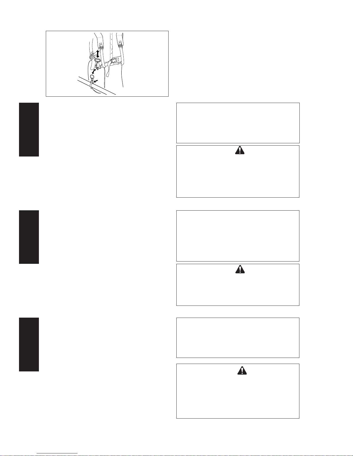
1. Harness quick-release pin
2. Suspension point
3. Ground level
Balance tool for a level
plane of cutting head
rotation
PREPARATION
Use a shoulder harness when provided or when recommended in this manual. Adjust both harness and the
suspension point on the unit so the unit hangs with the
cutting attachment a few centimetres above ground level.
The cutting attachment and shield should be level in all
directions. Harness the unit on the right side as shown.
Die Motorsense so
ausbalancieren, daß das
Arbeitswerkzeug parallel
zum Fußboden steht.
1. Spina a sgancio rapido
2. Punto di sospensione
3. Livello del suolo
Equilibrare l’attrezzo per
un taglio con rotazione
livellata
1. Schnellösseinrichtung
2. Trageöse
3. Schutzkleidung
VORBEREITUNG
Stets den Schultergurt tragen, wenn das im vorliegenden
Handbuch so empfohlen oder vorgeschrieben ist.
Sowohl das Gurtzeug als auch die Trageöse am Gerät
sind so zu justieren, daß das Gerät mit der
Schneidvorrichtung ein paar Zentimeter über dem Boden
hängt. Die Schneidvorrichtung und der Schutzschild
müssen sich in jeder Richtung auf einer Ebene befinden.
Den Tragegurt gemäß Darstellung rechts anbringen.
PREPARAZIONE
Utilizzare lo spallaccio se fornito o quando viene consigliato
dal manuale. Regolare la cintura ed il punto di sospensione
dell’attrezzo in modo che questo penzoli con l’accessorio
di taglio a pochi centimetri dal suolo. L’accessorio di taglio
e la protezione devono essere a livello in ogni direzione.
Appendere l’attrezzo sul fianco destro, come illustrato.
IN AGGIUNTA ALLE PROTEZIONI PER TESTA,
OCCHI E ORECCHIE, E’ CONSIGLIATO L’UTILIZZO
DI INDUMENTI ADERENTI, GUANTI PROTETTIVI E
SCARPE ROBUSTE CHE PROTEGGANO IL
CORPO DA EVENTUALI OGGETTI SCAGLIATI, E
CHE MIGLIORINO L’ADERENZA DEI PIEDI AL
TERRENO. NON INDOSSARE CRAVATTE,
GIOIELLI O QUALSIASI TIPO DI INDUMENTO
POCO ADERENTE CHE POTREBBE RESTARE
IMPIGLIATO NELLA MACCHINA. NON
INDOSSARE CIABATTE, SANDALI O CALZATURE
APERTE. IN ALCUNE SITUAZIONI POTREBBE
ESSERE NECESSARIO L’UTILIZZO DI UNA
PROTEZIONE TOTALE PER VISO E TESTA. PER
LAVORI DI DECESPUGLIAZIONE CON DISCO
(SOLO VERSIONE CON IMPUGNATURA AD “U”),
È DA CONSIDERARE L’UTILIZZO DI STIVALI E
PANTALONI PROTETTIVI.
AVVERTENZA PERICOLO
1
2
3
Page 10
10
SRM-4000/5000
E
N
G
L
I
S
H
D
E
U
T
S
C
H
I
T
A
L
I
A
N
O
a) Die Trageöse am Wellenrohr auf und ab bewegen, um
die richtige Balanceposition zu finden. So einstellen,
daß das Arbeitswerkzeug parallel zum Fußboden
ausgerichtet ist. Trageöse in dieser Positon arretieren.
Da es sich um einen frei beweglichen Aufhängungsring
handelt, verlagert sich das Gerät leicht seitwärts. Sie
müssen aber dennoch die Schneidvorrichtung und
den Schutzschild auf einer Achse von vorn nach
hinten nivellieren.
a) Slide suspension point up and down the tube to find
the right balance. Rotate the clamp to level the cutting
attachment and shield. Lock in position. If the
suspension point is a free-spinning type, the unit may
tend to roll over sideways, however, you should still
level the attachment and shield on the front-to-rear
axis.
a) Spingere il punto di sospensione su e giù sul tubo fino
a trovare il punto di equilibrio. Girare il fermo per
equilibrare l’accessorio di taglio, e fissarlo. Se il punto
di sospensione è del tipo a rotazione libera l’attrezzo
può tendere a sbilanciarsi lateralmente; è tuttavia
necessario livellare ugualmente l’accessorio sull’asse
anteriore-posteriore.
NOTE
A person’s size can affect the balancing adjustment.
Also the balancing procedure may not work with
some ECHO units on some persons. If the procedure
does not work for you, please ask your ECHO
servicing dealer for assistance.
WARNING DANGER
ECHO TRIMMERS AND BRUSHCUTTERS ARE
DESIGNED TO FIT A WIDE VARIETY OF BODY
SIZES, BUT MAY NOT BE ADJUSTABLE FOR
EXTREMELY TALL PERSONS.
DO NOT USE THE UNIT IF YOUR FEET CAN
REACH THE CUTTING ATTACHMENT WHEN THE
UNIT IS ATTACHED TO THE HARNESS.
AVVERTENZA PERICOLO
I TAGLIABORDI E DECESPUGLIATORI ECHO
SONO ADATTI A VARI TIPI DI CORPORATURE,
MA NON SONO SEMPRE REGOLABILI PER
PERSONE MOLTO ALTE. NON UTILIZZARE
L’ATTREZZO SE I PIEDI RAGGIUNGONO
L’ACCESSORIO DI TAGLIO QUANDO
L’ATTREZZO È MONTATO SULLO SPALLACCIO.
b) Balancing and levelling, as above, may require
relocation of the clamp and readjustment of the harness
straps. Also, each type of cutting attachment and
shield mounted on the unit may require balancing.
b) Beim oben beschriebenen Ausgleichen und Nivellieren
ist es u.U. erforderlich, die Trageöse anders zu
positionieren und die Gurte des Schultergurts anders
einzustellen. Außerdem kann es sein, daß die
verschiedenen Arten von Schneidvorrichtung und
Schutzschild am Gerät einzeln ausgeglichen werden
müssen.
b) In seguito al bilanciamento ed al livellamento può
essere necessario riposizionare il morsetto e regolare
sulla macchina lo spallaccio.
All’occorrenza riequilibrare gli apparati di taglio e la
protezione montati sull’attrezzo.
ANMERKUNG
Die Körpergröße einer Person kann sich auf die
Ausgleichjustierung auswirken.
Der Ausgleichvorgang funktioniert u.U. bei
bestimmten Personen an bestimmten ECHO Geräten
nicht. Wenn das Verfahren bei Ihnen nicht
funktioniert, wenden Sie sich bitte an den für Sie
zuständigen ECHO Vertragshändler.
ACHTUNG GEFAHR
ECHO TRIMMER UND FREISCHNEIDER SIND AUF
EINE VIELZAHL VERSCHIEDENER
KÖRPERGRÖSSEN AUSGELEGT, LASSEN SICH
ABER EVTL. FÜR BESONDERS GROSSE
PERSONEN NICHT JUSTIEREN.
N.B.
L’altezza della persona può influire sul bilanciamento.
Il procedimento di bilanciamento proposto dalla
ECHO per taluni attrezzi non è valido per tutti. Se non
dovesse funzionare nel vostro caso siete pregati di
rivolgervi al concessionario ECHO.
Page 11

11
SRM-4000/5000
E
N
G
L
I
S
H
D
E
U
T
S
C
H
I
T
A
L
I
A
N
O
e) Verschütteten Kraftstoff vom Gerät abwischen. Dann
mind. 3 m vom Auffüllpunkt weggehen, bevor Sie den
Motor anlassen.
f) Nie Kraftstoff nachfüllen, wenn Motor heiß ist oder gar
läuft.
g) Das Gerät nicht mit Kraftstoff im Tank lagern, da durch
auslaufendes Benzin ein Brand ausgelöst werden
könnte.
KÖRPERLICHE VERFASSUNG
Sie müssen körperlich und geistig gesund sein. Nicht
mit dem Gerät umgehen, wenn Sie Alkohol oder eine
Medizin bzw. eine Substanz eingenommen haben, die
Ihr Sehvermögen, Ihre Geschicklichkeit oder Ihre
Urteilsfähigkeit beeinträchtigen könnten.
MISCELA
Attenzione! Altamente infiammabile!
a) Utilizzare una tanica per carburante idonea.
b) Non fumare o avvicinare fiamme o scintille al
rifornimento di carburante.
c) Il serbatoio del carburante potrebbe essere sotto
pressione. Allentare sempre il tappo del carburante e
prima di rimuovere il tappo attendere che la pressione
compensi.
d) Riempire il serbatoio del carburante all’aperto su terreno
sgombro, e chiudere bene. Non fare rifornimento in
luoghi chiusi.
Allontanarsi dal luogo di rifornimento prima di avviare
il motore
Motor nicht dort anlassen, wo Sie Kraftstoff nachgefüllt
haben.
Do not start engine near fuelling spot
FUEL
It is highly flammable.
a) Use an appropriate type fuel container.
b) Do not smoke or bring flame or sparks near fuel
supplies.
c) The fuel tank may be under pressure. Always loosen
the fuel cap and wait for pressure to be equalized
before removing the cap.
d) Fill the fuel tank outdoors over bare ground and install
the fuel cap securely. Do not pour fuel indoors.
KRAFTSTOFF
Es ist höchst endzündbar.
a) Kraftstoffbehälter geeigneter Art benutzen.
b) In der Nähe von Kraftstoffvorräten darf nicht geraucht
werden, und es dürfen dort keine offenen Flammen
oder Funken vorkommen.
c) Der Kraftstofftank kann unter Druck stehen. Den
Kraftstoffdeckel stets etwas losschrauben und
abwarten, bis Druckausgleich besteht, bevor Sie den
Deckel abnehmen.
d) Kraftstofftank draußen auffüllen (wobei darauf zu
achten ist, daß keine feuergefährlichen Gegenstände
in der Nähe herumliegen) und den Tankdeckel fest
verschrauben. Nicht in Innenräumen mit Kraftstoff
auffüllen.
f) Non fare rifornimento se il motore è caldo, né fare il
pieno se il motore gira.
g) Non conservare l’attrezzo col carburante nel serbatoio,
in quanto una perdita di carburante potrebbe causare
un incendio.
CONDIZIONI FISICHE
L’operatore deve essere in buone condizioni di salute
mentale e fisica. Non utilizzare l’attrezzo sotto l’influenza
di alcol o farmaci o sostanze che potrebbero influire su
vista, destrezza o sulla capacità di giudicare le situazioni.
PHYSICAL CONDITION
You should be in good mental and physical health. Do not
operate if you are under the influence of alcohol or any
medication or substance which could affect your vision,
dexterity or judgement.
e) Asciugare il carburante versato sull’attrezzo, e
allontanarsi di almeno 3 m dal luogo di rifornimento
prima di avviare il motore.
e) Wipe any spilled fuel off the unit. Then move at least
3 m from the fuelling spot before starting the engine.
f) Never refuel while the engine is still hot, or fuel a
running engine.
g) Do not store the unit with fuel in its tank, because a fuel
leak could start a fire.
Page 12
12
SRM-4000/5000
E
N
G
L
I
S
H
D
E
U
T
S
C
H
I
T
A
L
I
A
N
O
AREA AND EQUIPMENT INSPECTION
Inspect the area before using the unit. Remove objects the
unit could throw. Remember where there are obstructions
to be avoided.
Inspect the unit before using it. Perform only maintenance
or adjustments for which the operator’s Manual gives
instruction. Do not try to repair the unit without proper
instruction. The unit should be serviced only by trained
ECHO dealer servicemen with the proper tools.
ISPEZIONE DELL’ATTREZZATURA E
DELL’AREA DI LAVORO
Ispezionare l’area circostante prima di utilizzare la macchina
e rimuovere corpi estranei che potrebbero essere scagliati
da questa.
Ispezionare l’attrezzo prima dell’uso. Eseguire solo la
manutenzione e le regolazioni spiegate nel manuale
istruzioni. Non tentare di riparare l’attrezzo senza adeguato
addestramento. L’attrezzo deve essere revisionato soltanto
da tecnici del concessionario ECHO, con utensili adatti.
UNTERSUCHUNG DES EINSATZGEBIETS
UND DES GERÄTS
Das Einsatzgebiet ist vor Benutzung des Geräts gründlich
zu untersuchen. Alle Objekte entfernen, die evtl. vom
Gerät hochgeschleudert werden könnten. Merken Sie
sich, wo Hindernisse sind.
Das Gerät vor dem Einsatz untersuchen. Nur diejenigen
Instandhaltungsaufgaben bzw. Justierungen vornehmen,
die in der Bedienungsanleitung vorgesehen sind.
Versuchen Sie nicht, das Gerät ohne ordnungsgemäße
Anleitung zu reparieren. Das Gerät darf nur von geschultem
Wartungspersonal des ECHO Vertragshändlers gewartet
werden, das über die entsprechenden Werkzeuge verfügt.
Folgendes sicherstellen:
a) Es läuft kein Kraftstoff aus dem Motor aus.
b) Die Befestigungselemente sind festgezogen und
vollzählig.
Verificare che:
a) Dal motore non fuoriesca carburante.
b) I dispositivi di fermo siano fissati e non ne manchi
nessuno.
Be sure that:
a) Engine does not leak fuel.
b) Fasteners are tight, and none are missing.
c) Silencer is in good condition.
d) The unit has the proper equipment-shield, handles,
harness, etc. -for the cutting attachment to be used.
e) If used on the unit, the cutting attachment is properly
tightened.
c) Der Schalldämpfer befindet sich in guter Verfassung.
d) Das Gerät ist für den Einsatz der Schneidvorrichtung
bzw. der Metallklinge -mit Schutzschild, Griffen,
Gurtzeug usw. -komplett ausgerüstet.
e) Beim Einsatz auf dem Gerät ist die Schneidvorrichtung
mittels Mutter richtig befestigt, scharf und frei von
Spannungsrissen.
c) La marmita sia in buono stato.
d) L’attrezzo sia provvisto degli accessori adatti
(protezione, impugnature, cintura, ecc.) per utilizzare
l’accessorio di taglio.
e) Se usato sulla macchina, l’accessorio di taglio è
adeguatamente fissato con un dado, è ben affilato e
non presenta incrinature dovute a colpi.
ACHTUNG GEFAHR
••
••
• WENN DIE SCHNEIDEVORRICHTIUNG
UNPASSEND MONTIERT IST, SIE KÖNNTE
LOSSPRINGEN.
••
••
• NIEMALS DEN MOTOR STARTEN, WENN DAS
ANTRIEBSGESTÄNGE NICHT MONTIERT IST, DA
ES SONST PASSIEREN KÖNNTE, DASS DER
MOTOR ZU HOCHTOURIG LÄUFT, BZW. DIE
KUPPLUNG ZERSPRINGT.
WARNING DANGER
••
••
• IMPROPER FIT WILL RESULT FLY OFF THE
CUTTING ATTACHMENT.
••
••
• NEVER START THE ENGINE IF THE POWER
TRANSMISSION SHAFT IS NOT IN PLACE TO
PREVENT THE ENGINE FROM OVER SPEEDING
OR THE CLUTCH FROM FLYING APART.
AVVERTENZA PERICOLO
••
••
• SE L’ACCESSORIO DI TAGLIO NON È BEN
FISSATO POTREBBE SALTARE.
••
••
• NON AVVIARE IL MOTORE SE L’ALBERO DI
TRASMISSIONE NON È CORRETTAMENTE
MONTATO, AL FINE DI IMPEDIRE CHE IL
MOTORE RAGGIUNGA UN REGIME ECCESSIVO
O CHE LA FRIZIONE SI STACCHI.
Page 13
13
SRM-4000/5000
E
N
G
L
I
S
H
D
E
U
T
S
C
H
I
T
A
L
I
A
N
O
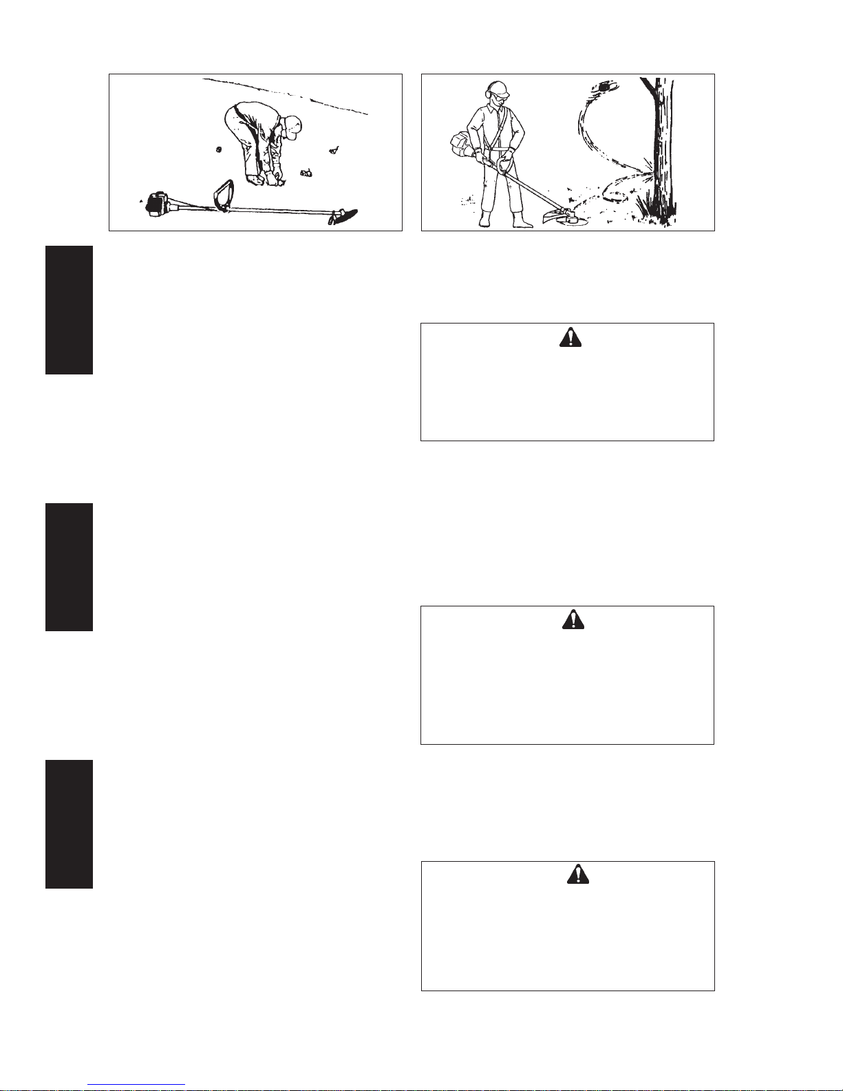
Lay the unit down on a clear area and set the controls for
starting. Be sure the cutting attachment cannot contact the
ground or any obstruction.
Hold the unit firmly down so you will not lose control during
starting. Do not start the unit in the air, or from the harness.
The unit could swing into your leg or an obstruction if you
lose control.
Start on ground with cutting attachment in the clear
Allontanarsi dal luogo di rifornimento prima di avviare
il motore
Motor nur beim am Boden liegenden Gerät starten
Posare l’attrezzo su uno spazio libero ed impostare i
comandi di avviamento. Verificare che l’accessorio di
taglio non tocchi il suolo o altri ostacoli.
Premere saldamente sulla macchina per non perdere il
controllo durante l’avviamento. Non avviarla tenendola in
aria o per lo cinghia, in quanto se si perde il controllo
potrebbe andare a sbattere contro una gamba o altro
ostacolo.
GENERAL OPERATION
Do not run the engine indoors, or where there is poor
ventilation.
Engine fumes contain deadly poisonous carbon monoxide.
Das Gerät auf einen freien Platz legen und die
Bedienungselemente zur Vorbereitung auf den Start
einstellen. Sicherstellen, daß die Schneidvorrichtung nicht
mit dem Erdboden oder einem Hindernis in Berührung
kommen kann.
Das Gerät fest in Position halten, damit Sie beim Starten
nicht die Gewalt darüber verlieren. Das Gerät darf nicht in
der Luft oder am Tragegurt hängend gestartet werden, da
es sonst auf Ihr Bein oder ein Hindernis zuschwenken
könnte, falls Sie die Gewalt verlieren.
FUNZIONAMENTO GENERALE
Non fare andare il motore in luoghi chiusi, o dove c’è
una scarsa ventilazione.
I fumi del motore contengono il letale monossido di carbonio.
ALLGEMEINE BEMERKUNGEN ZUM
BETRIEB
Niemals das Gerät in geschlossenen oder schlecht
belüftbaren Innenräumen benützen.
Die Abgase des Motors enthalten gefährliches
Kohlenmonoxyd. Das Einatmen kann tödlich sein.
Do not operate with a worn or damaged cutting attachment.
Do not run engine at full throttle without a load.
Do not hit rocks, stones, tree stumps, and other foreign
objects with the cutting attachment.
If cutting attachment strikes an obstruction, stop engine
immediately and inspect cutting attachment for damage.
Nicht mit verschlissener oder beschädigter
Schneidvorrichtung arbeiten.
Motor nicht ohne Belastung bei Vollgas laufenlassen.
Darauf achten, daß Sie keine Felsbrocken, Baumstümpfe
und anderen Fremdkörper mit dem Arbeitswerkzeug
berühren.
Wenn vom Arbeitswerkzeug ein Hindernis berührt wird,
den Motor sofort anhalten und die Schneidvorrichtung auf
Schäden überprüfen.
Non azionare il decespugliatore se il disco è consumato,
piegato, danneggiato o scalfito, o se il dado è consumato
o danneggiato.
Non azionare il motore al massimo senza carico.
Non urtare con il disco contro pietre, sassi, ceppi od altri
corpi estranei.
Se il disco colpisce un ostacolo, spegnere immediatamente
il motore e controllare se il disco è stato danneggiato.
Page 14

14
SRM-4000/5000
E
N
G
L
I
S
H
D
E
U
T
S
C
H
I
T
A
L
I
A
N
O
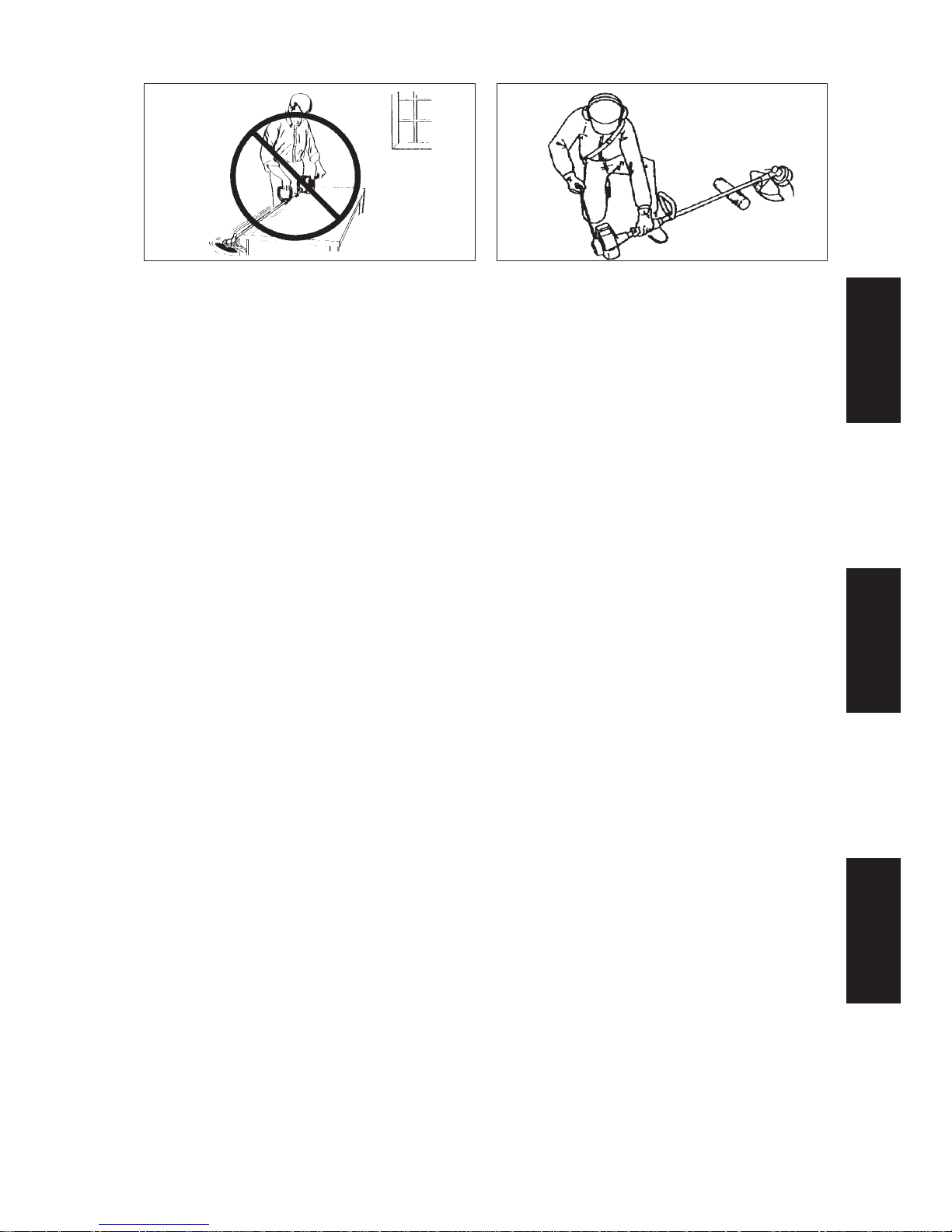
Do not raise the cutting attachment above knee height. If
raised higher, the cutting attachment will be more directly
in line with your face. Thrown objects may hit your face and
eyes.
Wear the recommended protective gear.
Never operate the unit without the proper guards, shoulder
harness and other protective devices.
Never operate the unit without good visibility and light.
Die empfohlenen Schutzvorrichtungen tragen.
Bevor Sie das Gerät starten, sollten Sie sich davon
überzeugen, daß das Nylonfadenschneidmesser an der
Schutzverlängerung angebracht ist und der Nylonfaden
nicht über das Fadenschneidmesser hinaussteht.
Das Gerät nie ohne angemessene Schutzeinrichtungen,
Schultergurt und andere Schutzmittel benutzen.
Das Gerät nie bei schlechter Sicht bzw. schlechtem Licht
einsetzen.
Non alzare l’accessorio di taglio al di sopra del livello del
ginocchio perché sarebbe più direttamente a livello con il
viso ed eventuali corpi estranei scagliati potrebbero colpire
viso ed occhi.
Indossare gli occhiali protettivi raccomandati.
Prima di avviare, controllare che la lama di taglio sia
posizionata adeguatamente nel paradisco e che il filo non
superi di molto la lama.
Non utilizzare mai l’unità senza parasassi, spallaccio e
senza gli altri dispositivi di protezione.
Non utilizzarlo o se visibilità o luce non sono buone.
15 m
Insist that persons in the RISK ZONE beyond the danger
zone wear eye protection to protect them from thrown
objects. If the unit must be used where there are unprotected
people, operate at a low throttle speed to reduce the risk.
Ensure that there are no children, bystanders, and pets in
the work area. Keep all children, bystanders and fellow
workers outside 15 m radius for brushcutters/
grasstrimmers.
Bestehen Sie darauf, daß Personen in der RISIKOZONE
(außerhalb der Gefahrenzone) ihre Augen vor
hochgeschleuderten Objekten schützen. Wenn das Gerät
in der Nähe ungeschützter Personen eingesetzt werden
muß, bei niedrigen Drehzahlen arbeiten, um das Risiko zu
mindern.
Zuschauer und Mitarbeiter sind zu warnen. Kinder und
Tiere müssen daran gehindert werden, sich bei Betrieb
von Trimmern/Motorsense auf mehr als 15 m Entfernung
zu nähern. Menschen, die in einem Radius von 15 m
arbeiten, müssen die gleiche Schutzausrüstung wie die
Bedienkraft tragen.
Accertarsi che le persone nella ZONA DI RISCHIO, oltre la
zona pericolosa, indossino mezzi di protezione per riparare
gli occhi da oggetti scagliati. Se l’attrezzo dovesse essere
utilizzato dove ci sono persone prive di mezzi di protezione,
regolare la valvola a farfalla per lavorare a velocità ridotta
al fine di ridurre il rischio.
Avvertire i presenti ed i colleghi di lavoro ed impedire che
bambini ed animali si avvicinino a meno di 15 m mentre il
tagliabordi/decespugliatore è in funzione. Coloro che
lavorano entro un raggio di 15 m devono indossare gli
stessi mezzi di protezione raccomandati per l’operatore.
Non permettere ad alcuno di entrare nella ZONA
PERICOLOSA. La zona pericolosa è un’area del raggio di
15 m.
Do not allow anyone to enter the operating DANGER
ZONE with you. The danger zone is an area of 15 m in
radius.
Erlauben Sie niemandem, Ihre GEFAHRENZONE zu
betreten. Die Gefahrenzone umfaßt einen Radius von
15 m.
Die Schneidvorrichtung nicht über Kniehöhe bringen.
Wenn sie höher gebracht wird, könnte sie leicht auf dieselbe
Höhe wie Ihr Gesicht geraten. Durch hochgeschleuderte
Objekte könnten Ihr Gesicht und Ihre Augen verletzt werden.
Page 15

15
SRM-4000/5000
E
N
G
L
I
S
H
D
E
U
T
S
C
H
I
T
A
L
I
A
N
O
Plötzliche Vibration?
Gerät sofort stillsetzen!
Vibrazioni Improvvise?
Spegnere immediatamente!
Shut down immediately if the unit starts to shake or vibrate.
A sudden vibration is a sign there may be dangerous
trouble, such as a broken flywheel, clutch or cutting
attachment, or loose parts.
Do not use the unit until the problem has been properly
diagnosed and corrected.
Falls das Gerät plötzlich zu rütteln bzw. zu vibrieren
beginnt, ist es sofort auszuschalten.
Ein plötzliches Vibrieren ist ein Hinweis darauf, daß
gefährliche Probleme wie z.B. ein beschädigtes
Schwungrad oder eine schadhafte Kupplung bzw.
Schneidvorrichtung vorliegen oder sich bestimmte Teile
gelöst haben.
Das Gerät darf erst dann wieder eingesetzt werden, wenns
Problem richtig erkannt und behoben worden ist.
Spegnere immediatamente la macchina se iniziasse ad
oscillare o vibrare.
La vibrazione improvvisa indica un probabile guasto
pericoloso, come ad esempio volano, frizione o accessorio
di taglio spezzati, o parti allentate.
Non utilizzare l’accessorio se non quando il problema sarà
stato correttamente diagnosticato e risolto.
Sudden vibration?
Shut down immediately!
Stop the engine before leaving the machine, children are
not allowed to use the machine, stop the machine between
different working places.
If you are approached, stop the engine and cutting
attachment immediately. Keep your hands and body away
from silencer to prevent heat injury while the engine is hot.
Sollte sich Ihnen eine Person nähern wollen, sofort den
Motor und das Arbeitswerkzeug zum Stillstand bringen.
Halten Sie Ihre Hände und andere Körperteile vom
Schalldämpfer fern, da Sie sonst gefährliche
Verbrennungen erleiden können, solange der Motor heiß
ist.
Se avvicinati da gualcuno, fermare subito motore e
accessorio di taglio.
Tenere le mani e la propria persona a distanza dalla
marmitta, onde evitare di ferirsi mentre il motore è caldo.
Motor abstellen, wenn Sie sich vom Gerät entfernen.
Keine Kinder mit dem Gerät arbeiten lassen. Bei
Arbeitsunterbrechung und Wechsel der Einsatzstelle Motor
abstellen.
Spegnete il motore prima di lasciare la macchina, i bambini
non devono toccare la macchina, spegnete la macchina
tra un traferimento da una zona di lavoro all’altra.
WARNING DANGER
EYE PROTECTION SHOULD BE CONSIDERED
FOR EVERYONE IN THE ZONE OF RISK. RISK OF
EYE INJURY DIMINISHES WITH DISTANCE.
ACHTUNG GEFAHR
BEACHTEN SIE BITTE, DASS ALLE PERSONEN
DIE SICH IN DER RISIKOZONE BEFINDEN EINEN
GEEIGNETEN AUGENSCHUTZ TRAGEN.
DIE GEFAHR VON AUGENVERLETZUNGEN
VERRINGERT SICH MIT ZUNAHME DES ABSTADS
ZUM GERÄT.
AVVERTENZA PERICOLO
E’ NECESSARIO CHE CHIUNQUE SI TROVI
NELL’AREA DI LAVORO INDOSSI PROTEZIONI
PER GLI OCCHI. TENERSI DISTANTI SE
POSSIBILE.
Page 16

16
SRM-4000/5000
E
N
G
L
I
S
H
D
E
U
T
S
C
H
I
T
A
L
I
A
N
O
When the unit is turned off, make sure the cutting attachment
stops before the unit is set down.
A cutting attachment can injure while it continues to spin
after the engine is shut off or throttle control is released.
If the cutting attachment rotates after throttle is returned to
idle, carburettor adjustment is required. Follow instruction
on this manual to make the adjustment yourself, or have
the carburettor adjusted by your ECHO dealer.
Keep feet and hands away until rotation stops.
Halten Sie Hände und Füße fern, solange bis das
Werkzeug stoppt.
Tenete lontani piedi e mani finché la testina non smette
di girare.
Nach Ausschalten des Motors abwarten bis die Rotation
des Arbeitswerkzeuges ganz unterbleibt, bevor Sie das
Gerät ablegen.
Wenn das Arbeitswerkzeug nach abschalten des Motors,
oder loslassen des Gashebels noch rotiert, kann dies zu
Verletzungen führen.
Sollte das Arbeitswerkzeug noch rotieren, nachdem der
Motor auf Leerlauf übergegangen ist, muß der Vergaser
justiert werden. Sie können die Justierung unter Befolgung
der vorliegenden Bedienungsanleitung selbst vornehmen,
oder den Vergaser vom Kundendienst Ihres ECHO
Vertragshändlers justieren lassen.
All maintenance and adjustments given in this manual
should be performed by you or your ECHO servicing dealer
on a timely basis.
All required service or repair must be done only by ECHO
servicing dealer. Never attempt to use an incomplete or
one fitted with unauthorized modification.
Alle in der Bedienungsanleitung aufgeführten
Instandhaltungs-und Justagearbeiten sind entweder
von Ihnen oder dem Kundendienst Ihres ECHO
Vertragshändlers auf Zeitbasis durchzuführen.
Alle erforderlichen Wartungs-oder Reparaturarbeiten
dürfen nur von geschultem Personal der ECHO
Vertragswerkstatt durchgeführt werden. Niemals eine
unvollständige Maschine bzw. eine mit nicht genehmigten
Modifikationen benutzen.
Quando l’unità è spenta, assicurarsi che l’accessorio di
taglio si fermi prima di riporla.
L’apparato di taglio può causare ferite qualora continui a
girare una volta spento il motore o con l’acceleratore
rilasciato.
Se continuasse a girare una volta rilasciato l’acceleratore,
procedere alla regolazione del carburatore. Per procedere
voi stessi alla regolazione, seguire le istruzioni contenute
in questo Manuale, oppure rivolgersi al rivenditore ECHO
più vicino.
Le operazioni di manutenzione e le regolazioni richieste,
illustrate in questo Manuale, dovrebbero essere effettuate
da Voi stessi o dal Vostro rivenditore ECHO periodicamente.
Tutte le operazioni di servizio o le riparazioni devono
essere effettuate esclusivamente da un rivenditore
autorizzato ECHO. Non usare mai un’unità incompleta o
sottoposta a modifiche non autorizzate.
Page 17

17
SRM-4000/5000
E
N
G
L
I
S
H
D
E
U
T
S
C
H
I
T
A
L
I
A
N
O
1. Quick-release pin
2. Pull out
3. Shaft tube
1. Schnellöseeinrichtung
2. Ziehen
3. Antriebsgestänge
1. Spina a sgancio rapido
2. Tirare
3. Asta
AVVERTENZA PERICOLO
IN CASO DI EMERGENZA TOGLIERE IL
DECESPUGLIATORE UTILIZZANDO IL FERMO A
SGANCIO RAPIDO SITUATO SULLA CINTURA.
ACHTUNG GEFAHR
IM NOTFALL ENTLEDIGEN SIE SICH DES
GERÄTS MIT HILFE DER
SCHNELLÖSEEINRICHTUNG TRAGEGURT.
WARNING DANGER
IN CASE OF AN EMERGENCY, USE QUICKRELEASE PIN ON HARNESS TO FREE YOURSELF
FROM UNIT.
Lavorare sempre con entrambe le mani sulle impugnature.
Non lavorare mai con una sola mano.
Le dita ed il pollice di ogni mano devono afferrare
saldamente le impugnature.
Do not operate one-handed
Non lavorare con una sola mano
Nicht einhändig arbeiten
Stets beide Hände an den Griffen halten. Nie einhändig
arbeiten.
Das Gerät stets so halten, daß Sie die Griffe mit Daumen
und Fingern umgreifen.
Always use both hands on the handles. Do not operate
one-handed.
Always hold the unit with the fingers and thumbs encircling
the handles.
3
1
2
Page 18

18
SRM-4000/5000
E
N
G
L
I
S
H
D
E
U
T
S
C
H
I
T
A
L
I
A
N
O
• Keep your body warm, especially the head and neck, feet
and ankles, and hands and wrists.
• Maintain good blood circulation by performing vigorous
arm exercises during frequent work breaks, and also by
not smoking.
• Limit the number of hours of operation.
Try to fill each day with jobs where operating the trimmer
or other hand-held power equipment is not required.
• If you experience discomfort redness and swelling of the
fingers, followed by whitening and loss of feeling, consult
your physician before exposing yourself further to cold
and vibration.
VIBRATION AND COLD
It is believed that a condition called Raynaud’s Phenomenon which affects the fingers of certain individuals may be
brought about by exposure to vibration and cold. Exposure
to vibration and cold may cause tingling and burning,
followed by loss of colour and numbness in the fingers.
The following precautions are strongly recommended
because the minimum exposure which might trigger the
ailment is unknown.
VIBRATION UND KÄLTE
Es wird vermutet, daß eine Beschwerde namens RaynaudSyndrom, die die Finger bestimmter Personen befällt,
durch Arbeit bei Vibration und Kälte herbeigeführt werden
kann. Wenn man bei Vibration und Kälte arbeitet, kann
sich ein Prickeln und Brennen bemerkbar machen, dem
sich Farblosigkeit und Gefühllosigkeit der Finger
anschließen.
Die nachstehend aufgeführten Vorkehrungen sind sehr
zu empfehlen, da die Mindestwerte, bei denen diese
Krankheit ausgelöst wird, nicht bekannt sind.
• Den Körper-insbesondere Kopf und Nacken, Füße und
Fußgelenke sowie Hände und Handgelenke warmhalten.
• Häufige Pausen einlegen, in deren Verlauf Sie den
Kreislauf durch intensive Armübungen anregen und
nicht rauchen.
• Die Betriebsstunden auf ein Minimum reduzieren. Jeden
Arbeitstag so einteilen, daß auch andere Arbeiten
verrichtet werden, bei denen kein Trimmer oder ein
anderes handgehaltenes Motorgerät eingesetzt wird.
• Wenn Ihre Finger schmerzen, rot und angeschwollen
sind, und schließlich ganz bleich und gefühllos werden,
müssen Sie den Arzt aufsuchen, bevor Sie sich wieder
der Kälte und Vibration aussetzen.
• Tenere il corpo caldo, soprattutto testa, collo, piedi,
caviglie, mani e polsi.
• Mantenere una buona circolazione del sangue facendo
vigorosi esercizi con le braccia durante frequenti pause
di lavoro, ed evitare di fumare.
• Limitare il numero di ore di impiego. Cercare di riempire
ogni giornata con lavori che non richiedano l’utilizzo di
altre macchine.
• Se si accusano disagi e disturbi, se si riscontrano
arrossamenti e gonfiore delle dita seguiti da pallore e
perdita di sensibilità, rivolgersi al proprio medico prima
di esporsi di nuovo al freddo ed alle vibrazioni.
LE VIBRAZIONI E IL FREDDO
Si ritiene che una condizione definita fenomeno di Raynaud,
che colpisce le dita di alcune persone, sia causata
dall’esposizione alle vibrazioni ed al freddo. L’esposizione
al freddo ed alle vibrazioni può causare formicolio e
bruciore seguiti da pallore e intorpidimento delle dita. Si
consiglia vivamente di osservare le seguenti precauzioni
in quanto non si conosce l’esposizione minima che causa
i disturbi.
Page 19

19
SRM-4000/5000
E
N
G
L
I
S
H
D
E
U
T
S
C
H
I
T
A
L
I
A
N
O
Painful or numb fingers?
See your doctor immediatelty!
REPETITIVE STRESS INJURIES
It is believed that overusing the muscles and tendons of the
fingers, hands, arms and shoulders may cause soreness,
swelling, numbness, weakness and extreme pain to the
areas just mentioned. Certain repetitive hand activities
may put you at a high risk for developing a repetitive stress
injury (RSI).
TENDOPERIOSTOSEN
(Ermüdungserscheinungen von Sehnen
und Knochenhaut)
Es wird angenommen, daß eine Überanstrengung der
Muskeln und Sehnen der Finger, Hände, Arme und
Schultern in den betreffenden Körperteilen Schmerz,
Schwellungen, Gefühllosigkeit, Schwäche und auch akuten
Schmerz verursachen kann. Durch bestimmte wiederholte
Handbewegungen können Sie sich einem erhöhten Risiko
der Entwicklung von Tendoperiostosen aussetzen.
Schmerzende oder gefühllose Finger?
Sofort einen Arzt aufsuchen!
Dita dolorose o intorpidite?
Rivolgersi al medico!
To reduce the risk of RSI, do the following:
• Avoid using your wrist in a bent, extended or twisted
position.
• Take periodic breaks to minimize repetition and rest your
hands. Reduce the speed and force in which you do the
repetitive movement.
• Do exercises to strengthen hand and arm muscles.
• See a doctor if you feel tingling, numbness or pain in your
fingers, hands, wrists or arms. The sooner RSI is
diagnosed, the more likely permanent nerve and muscle
damage can be prevented.
Das Risiko von Tendoperiostosen/Karpaltunnelsyndrom
wird folgendermaßen gemindert:
LESIONI DA SFORZI RIPETITIVI
Si ritiene che l’uso eccessivo dei muscoli e dei tendini di
dita, mani, braccia e spalle possa causare dolore, gonfiore,
intorpidimento, debolezza e fortissimi dolori nelle zone
menzionate. Alcune attività manuali ripetitive possono
essere causa di alto rischio per lo sviluppo di lesioni da
sforzi ripetitivi.
Per ridurre il rischio di lesioni da sforzi ripetitivi:
• Evitare di usare il polso piegato, allungato o girato.
• Fare pause ad intervalli regolari per ripetere il meno
possibile gli stessi movimenti e far riposare le mani.
• Ridurre la velocità e la forza con cui il movimento ripetitivo
viene eseguito.
• Fare esercizi per rafforzare i muscoli della mano e del
braccio.
• Consultare un medico se si accusano formicolio,
intorpidimento o dolori nelle dita, nelle mani, nei polsi o
nelle braccia. La tempestiva diagnosi delle lesioni da
sforzi ripetitivi offre maggiore possibilità di impedire
danni permanenti a nervi e muscoli.
• Achten Sie darauf, daß Sie Ihr Handgelenk nicht zu sehr
beugen, strecken oder verdrehen.
• Von Zeit zu Zeit Pausen einlegen, um
Wiederholungsbewegungen auf ein Minimum zu
beschränken. Hände ruhen lassen. Die Geschwindigkeit
und den Kraftaufwand reduzieren, mit der Sie die
Wiederholungsbewegung ausführen.
• Zwecks Stärkung der Hand- und Armmuskulatur
Übungen durchführen.
• Einen Arzt aufsuchen, wenn Sie ein Prickeln,
Gefühllosigkeit oder Schmerzen in Ihren Fingern,
Händen, Handgelenken oder Armen fühlen. Je eher
Tendoperiostosen erkannt werden, desto
wahrscheinlicher ist es, daß sich eine anhaltende
Beschädigung von Nerven und Muskeln verhindern läßt.
Page 20

20
SRM-4000/5000
E
N
G
L
I
S
H
D
E
U
T
S
C
H
I
T
A
L
I
A
N
O
RULES FOR SAFE OPERATION
(WITH NYLON LINE CUTTING HEAD)
1. Winkel zur Wand hin
2. Schneidgut
1. Angle to wall
2. Debris
The basic cutting actions pictured are:
Trimming, scything, scalping and lawn edging.
These actions are as follows:
TRIMMING: This is feeding the trimmer carefully into the
material you wish to cut. Tilt the head slightly to direct the
debris away from you. If cutting up to a barrier such as a
fence, wall or tree, approach from an angle where any
debris ricocheting off the barrier will fly away from you.
Move the line head or line disc slowly until the grass is cut
right up to the barrier, but do not jam (overfeed) the line
into the barrier. If trimming up to wire mesh or chain link
fencing, be careful to feed only up to the wire. If you go too
far, the line will snap off around the wire.
Trimming can be done to cut through weed stems one at
a time. Place the nylon line cutter near the bottom of the
weed never high up, which could cause the weed to
chatter and catch the line. Rather than cut the weed right
through, just use the very end of the line to wear through
the stem slowly.
Die hier dargestellten Schneidvorgänge sind wie folgt:
Trimmen, Mähen, Skalpieren und Kantenschneiden.
TRIMMEN: Hierbei wird der Trimmer vorsichtig an das zu
schneidende Material herangeführt. Den Fadenkopf etwas
schrägstellen, damit das Schneidgut von Ihnen weggeleitet
wird. Wenn man auf eine Barriere zuschneidet, wie z.B.
einen Zaun, eine Wand oder einen Baum, müssen Sie sich
in einem Winkel vorarbeiten, so daß von der Barriere
abprallendes Schneidgut von Ihnen weggeleitet wird.
RICHTLINIEN ZUR BETRIEBSSICHERHEIT
(MIT NYLONFADENKOPF)
Bewegen Sie den Nylonfadenkopf oder die Fadenscheibe
langsam, bis das Gras am Hindernis (Baum, Mauer...)
abgemäht ist. Wenn Sie an einem Draht- oder
Kettengliedzaun entlang Trimmarbeiten durchführen,
dürfen Sie den Nylonfaden nicht so weit vorschnellen
lassen, daß er durch Berührung mit dem Zaun reißt.
Beim Trimmen können Unkrauthalme nacheinander
durchgeschnitten werden. Die NylonfadenSchneidvorrichtung unten-nie oben-an der Pflanze
ansetzen, da sich die Pflanze sonst evtl. nur beugt und
dann wieder aufrichtet und sich in dem Nylonfaden
verfangen könnte. Anstatt das Unkraut ganz
durchzuschneiden, führen Sie das Ende des Nylonfadens
allmählich durch den Unkrauthalm.
NORME DI SICUREZZA
(CON TESTINA A FILO DI NYLON)
1. Angolo con il muro
2. Detriti
Le illustrazioni a fianco mostrano le operazioni basilari:
Ripulire i bordi, falciatura, radere al suolo e bordure.
Le azioni pertinenti sono:
RASATURA: È necessario prestare molta attenzione con
il materiale che si desidera tagliare. Scrollate leggermente
il disco per togliere i detriti. Se state per tagliare su una
barriera, come ad esemplo una palizzata, un muro o un
albero, avvicinatevi da un’angolazione tale per cui i detriti
che possono saltare non vi vengano contro.
Muovete la testina di taglio o il disco lentamente finché
l’erba non è stata tagliata fino al punto desiderato, ma non
insistete troppo con il filo perché se andate a cozzare
contro una rete, se il filo è troppo lungo va ad avvolgersi e
ad impigliarsi con la rete.
I bordi si ripuliscono anche falciando un gambo di erbacce
per volta. Mettere l’apparato di taglio con filo di nylon
accanto alla base del fascio, mai in alto dove l’erbaccia
potrebbe vibrare ed impigliarsi nel filo. Anziché falciare
completamente le erbacce, tagliare lentamente il gambo
con la punta del filo.
3. Knife side raised
4. Angle to ground
3. schräggestelltes
Arbeitswerkzeug
4. Winkel zum Boden hin
3. Lato lama alzato
4. Angolo con il suolo
1
2
3
4
Page 21

21
SRM-4000/5000
E
N
G
L
I
S
H
D
E
U
T
S
C
H
I
T
A
L
I
A
N
O
(B): Edging
SCALPING AND EDGING: Both of these are done with the
line head or line disc tilted at a steep angle. Scalping is
removing top growth, leaving the earth bare. Edging is
trimming the grass back where it has spread over a
pavement or driveway. During both edging and scalping,
hold the unit at a steep angle in a position where the debris,
and any dislodged dirt and stone, will not come back
towards you even if it ricochets off the hard surface.
Although the pictures show how to edge and scalp, every
operator must find for himself the angles which suit his
body size and cutting situation.
(A): Scalping
(A): Skalpieren
(A): Rasatura al suolo
SKALPIEREN UND KANTENSCHNEIDEN: Beides wird
mit dem Nylonfadenkopf oder der Fadenscheibe gemacht,
indem Sie steil zum Gras gekippt werden. Beim Skalpieren
wird die Vegetation so weit geschnitten, daß nur der kahle
Boden zurückbleibt. Beim Kantenschneiden wird das Gras
zurückgetrimmt, wo es über einen Fußgängerweg oder
eine Zufahrt gewachsen ist. Sowohl beim Kantenschneiden
als auch beim Skalpieren ist das Gerät in einem steilen
Winkel so zu halten, daß das Schneidgut sowie sich aus
dem Boden lösende Steine und Schmutz nicht auf Sie
zugeschleudert werden.
Obwohl Sie der Darstellung entnehmen können, wie das
Kantenschneiden und Skalpieren ablaufen, muß jede
Bedienkraft für sich selbst herausfinden, in welchem Winkel
sie ihrer Körpergröße und Schneidsituation nach am besten
arbeitet.
RIFINITURA E BORDATURA: La bordatura viene
effettuata tenendo il disco inclinato in modo tale da formare
un angolo acuto, e tale operazione è necessaria per
eliminare la crescita, lasciando solo la base di terra. Viene
effettuata anche per eliminare la crescita dell’erba da un
marciapiede o un’aiuola.
Durante l’azione di rifinitura tenete il decespugliatore in
moda che la testina filo nylon o il disco formino
un’angolazione tale che eventuali detriti non vengano a
colpirvi.
Sebbene le illustrazioni mostrino come radere il suolo ed
eseguire le bordatura, l’operatore deve trovare da sé
l’inclinazione adatta al suo corpo ed al taglio desiderato.
SCYTHING: This is the cutting or mowing of large grassy
areas by sweeping or swinging the trimmer in a level arc.
Use a smooth, easy motion. Do not try to hack or chop
down the grass. Tilt the line head or line disc to direct the
debris away from you on the scything stroke. Then return
without cutting grass for another stroke. If you are well
protected and do not care whether some debris is thrown
in your direction, you may scythe in both directions.
MÄHEN: Hierbei werden große Grasflächen durch
Schwingen des Trimmers in einem Halbkreis auf
gleichmäßiger Höhe gemäht. Es empfiehlt sich eine
gemessene, gleichmäßige Arbeitsweise. Auf keinen Fall
versuchen, das Gras durch Hackbewegungen zu
schneiden. Kippen Sie den Nylonfadenkopf oder die
Fadenscheibe so, daß das gemähte Gras weg von Ihnen
auf die bereits gemähte Fläche geworfen wird. Dann ohne Gras zu schneiden - das Gerät zurückführen, um den
nächsten sensenartigen Hub auszuführen. Wenn Sie gut
geschützt sind und es Ihnen nichts ausmacht, wenn
Schneidgut auf Sie zu geschleudert wird, können Sie in
beide Richtungen mähen.
FALCIATURA: Si tratta del taglio di aree erbose piuttosto
estese, descrivendo un arco con il decespuglistore.
Muovetelo lentamente e non a scatti, senza cercare di
appiattire o tranciare l’erba. Tenete il disco leggermente
inclinato in modo da far saltare gli eventuali detriti lontano
da voi, ripetendo il movimento ogni tanto. Se siete ben
protetti ed equipaggiati, e quindi non dovete preoccuparvi
di eventuali detriti potete falciare in ambedue le direzioni.
(B): Kantenschneiden
(B): Bordtura
(A) (B)
Page 22

22
SRM-4000/5000
E
N
G
L
I
S
H
D
E
U
T
S
C
H
I
T
A
L
I
A
N
O
Tilting the head to the wrong side will shoot the debris
toward you. If the nylon line cutter is held flat to the ground
so that cutting occurs on the whole line circle, debris will be
thrown at you, drag will slow the engine, and you will use
up a lot of line.
WARNING DANGER
USE ONLY FLEXIBLE, NON-METALLIC LINE
RECOMMENDED BY KIORITZ CORPORATION.
1. Debris
2. Cut on this side
For nearly all cutting, it is good to tilt the nylon cutter so that
contact is made on the part of line circle where the line is
moving away from you and the shield (See appropriate
picture). This results in the debris being thrown away from
you.
Nylonfadenkopf oder Fadenscheibe drehen sich
entgegen dem Uhrzeigersinn.
Das Fadenschneidemesser befindet sich links vom
Schutzschild.
Bei fast allen Schneidarbelten empfiehlt es sich, den
Nylonfadenkopf so schrägzustellen, daß der Kontakt in
dem Teil des Schneidkreises erfolgt, wo der Nylonfaden
sich von Ihnen und dem Schutzschild wegbewegt (s. die
entsprechende Abbildung). Dadurch wird das Schneidgut
von Ihnen weggeleitet.
La testina filo nylon o il disco girano in senso antiorario.
La lama si trova a sinistra della protezione.
Per quasi ogni tipo di taglio è buona pratica inclinare il filo
di nylon in modo che il contatto abbia luogo sulla sezione
del cerchio tracciato dal filo quando si sposta lontano
dall’operatore e dalla protezione (vedi pertinente
illustrazione). In questo caso i detriti vengono scagliati
lontano dall’operatore.
Inclinando la testina in direzione errata l’operatore fa
volare i detriti verso di sé. Se il filo viene tenuto piatto
rispetto al suolo in modo che la falciatura abbia luogo su
tutto il cerchio tracciato, i detriti saranno scagliati verso
l’operatore, la resistenza farà rallentare il motore e si userà
molto filo.
AVVERTENZA PERICOLO
USARE SOLO FILO FLESSIBILE NON METALLICO
CONSIGLIATO DALLA KIORITZ CORPORATION.
Wenn Sie den Fadenkopf zur falschen Seite neigen, wird
das Schneidgut auf Sie zugeschleudert. Wenn der
Nylonfadenkopf flach gegen den Boden gehalten wird, so
daß der Schneidvorgang über den gesamten Schneidkreis
erfolgt, wird das Schneidgut auf Sie zugeschleudert, die
Motordrehzahl durch den Widerstand verringert, und es
wird sehr viel mehr Nylonfaden verwendet.
ACHTUNG GEFAHR
NUR DEN VON DER FIRMA KIORITZ
CORPORATION EMPFOHLENEN FLEXIBLEN,
NICHTMETALLISCHEN NYLONFADEN
VERWENDEN.
Nylon line head or disc rotates anticlockwise.
The knife will be on the left side of the shield.
1. Schneidgut
2. Auf dieser seite Schneiden
1. Detriti
2. Tagliare da questo lato
1
2
Page 23

23
SRM-4000/5000
E
N
G
L
I
S
H
D
E
U
T
S
C
H
I
T
A
L
I
A
N
O
WARNING DANGER
USE EXTREME CAUTION WHEN OPERATING
OVER BARE SPOTS AND GRAVEL, BECAUSE
THE LINE CAN THROW SMALL ROCK PARTICLES
AT HIGH SPEEDS. THE SHIELD ON THE UNIT
CANNOT STOP OBJECTS WHICH BOUNCE OR
RICOCHET OFF HARD SURFACES.
Do not trim near cars or pedestrians.
Nicht in der Nähe von Fahrzeugen oder Fussgängern
trimmen.
Non rifinire i boroi vicino ad auto o pedoni.
ACHTUNG GEFAHR
BEIM ARBEITEN AN VEGETATIONSFREIEN
STELLEN BZW. KIESWEGEN SEHR VORSICHTIG
VERFAHREN, DA DURCH DEN NYLONFADEN
KLEINE GESTEINSBROCKEN
HOCHGESCHLEUDERT WERDEN KÖNNEN.
DER SCHUTZSCHILD KANN KEINE
FREMDKÖRPER AUFHALTEN, DIE VON HARTEM
UMTERGRUND ABPRALLEN ODER
HOCHGESCHLEUDERT WERDEN.
AVVERTENZA PERICOLO
FARE ATTENZIONE QUANDO SI LAVORA SU
TERRA NUDA O SU GHIAIA IN QUANTO IL FILO
PUÒ SCAGLIARE FRAMMENTI DI SASSI AD ALTA
VELOCITÀ. LA PROTEZIONE NON FERMA
OGGETTI CHE RIMBALZANO O SALTANO SU
SUPERFICI DURE.
Always wear proper eye protection against thrown objects.
Objects can bounce up at you from the ground under the
shield, or ricochet off any nearby hard surface.
Do not trim at high speed near roadways when there is
traffic, or in places where there are pedestrians. If you must
trim where people are in the zone of risk use a much lower
or reduced speed, by using a partial trigger setting. Do not
use full throttle.
Indossare sempre di protezione gli occhi per ripararli da
oggetti scagliati. Gli oggetti possono rimbalzare verso
l’operatore da sotto la protezione oppure da una superficie
dura.
Non ri finire i bordi ad alta velocità accanto a strade quando
vi è traffico, oppure in luoghi frequentati da pedoni. Quando
si deve lavorare in presenza di persone nella zona di
rischio usare una velocità molto più bassa o ridotta,
utilizzando una posizione intermedia della leva. Non usare
la leva del gas al massimo.
Zum Schutz vor hochgeschleuderten Gegenständen stets
angemessenen Augenschutz tragen. Gegenstände können
vom Boden her unterhalb des Schutzschildes
hochschnellen oder von nahegelegenen Objekten
zurückpralen.
Den Trimmer nicht mit hohen Drehzahlen entlang Straßen
einsetzen, wo viel Verkehr ist oder in Gegenden, wo
Passanten vorbeigehen. Wenn es sich nicht vermeiden
läßt, daß Sie dort arbeiten, wo sich in der Risikozone
Menschen befinden, den Gashebel nur leicht drücken.
Nicht mit Vollgas arbeiten.
Page 24

24
SRM-4000/5000
E
N
G
L
I
S
H
D
E
U
T
S
C
H
I
T
A
L
I
A
N
O
Avoid wire
Draht vermeiden
Evitare i filli
Avoid nylon line contact with broken wire fencing. Pieces
of wire broken off by the trimmer can be hurled at high
speeds.
Darauf achten, daß der Nylonfaden nicht mit beschädigtem
Zaundraht in Berührung kommt. Vom Trimmer
abgebrochene Drahtstücke können mit hoher
Geschwindigkeit durch die Luft geschleudert werden.
Evitare che il filo di nylon venga a contatto con rete
metallica. I pezzi di rete spezzata dal decespugliatore
possono essere scagliati ad alta velocità.
Do not push the line into tough weeds, trees, or wire
fences. Pushing the line into chicken wire, chain link
fencing or thick brush can result in snapped-off line ends
being hurled back at the operator. The proper way is to cut
right up to a barrier, such as any of those mentioned, but
never run the line into or through the obstruction. Do not cut
closely to obstruction or barrier.
Line pushed into wire fencing will snap off.
ll filo spinto nella rete metallica si spezza.
Wenn sich der Nylonfaden im Drahtzaun verfängt,
reißt er.
Den Nylonfadenkopf nicht in zähes Unkraut, Bäume oder
Zäune eindringen lassen. Wenn der Nylonfaden in
Hühnerdraht, Zäune oder dichtes Gestrüpp eindringt, kann
es vorkommen, daß abgerissene Fadenstücke gegen die
Bedienungsperson geschleudert werden. Am besten
arbeitet man sich so weit wie möglich an die jeweilige
Barriere heran, ohne den Nylonfaden je in das Hindernis
vordringen zu lassen. Nicht direkt an dem Hindernis bzw.
der Barriere schneiden.
Non spingere il filo tra erbacce robuste, alberi o reti
metalliche. Quando si spinge il filo in rete zincata leggera
o recinzioni in tessuto metallico o fitta vegetazione
l’operatore rischia di venire colpito dalle estremità spezzate
del filo. Il metodo corretto è di falciare fino ad un ostacolo
come quelli già accennati, senza mai permettere che il filo
entri o penetri nell’ostacolo. Non falciare vicino ad barriere
od ostacoli.
WARNING DANGER
ALWAYS STOP THE ENGINE WHEN A CUTTING
ATTACHMENT JAM OCCURS. DO NOT ATTEMPT
TO REMOVE AN OBJECT CAUSING A JAM IF THE
ENGINE IS RUNNING. INJURY CAN OCCUR IF A
JAM IS REMOVED AND THE CUTTING
ATTACHMENT SUDDENLY STARTS.
ACHTUNG GEFAHR
STETS DEN MOTOR ABSTELLEN, WENN SICH
DAS ARBEITSWERKZEUG FESTGESETZT HAT.
NICHT VERSUCHEN, DIE URSACHE BEI
LAUFENDEM MOTOR ZU BESEITIGEN.
ES KÖNNTEN SICH SCHWERE VERLETZUNGEN
ERGEBEN, WENN DAS ARBEITSWERKZEUG
PLÖTZLICH FREI WIRD UND ANLÄUFT.
DAS RICHTIGE ARBEITSWERKZEUG BENUTZEN.
AVVERTENZA PERICOLO
ARRESTARE SEMPRE IL MOTORE QUANDO
L’ACCESSORIO DI TAGLIO SI INCEPPA. NON
CERCARE DI RIMUOVERE LA CAUSA
DELL’INCEPPAMENTO MENTRE IL MOTORE
GIRA. SE NEL RIMUOVERE L’INCEPPAMENTO
L’ACCESSORIO DI TAGLIO SI AVVIA
IMPROVVISAMENTE SI POSSONO CAUSARE
GRAVI LESIONI.
AVVERTENZA PERICOLO
NON USARE IL DECESPUGLIATORE IN AREE IN
CUI VI SONO FILI DI RETE METALLICA
SPEZZATA. RIMUOVERE I PEZZI DI RETE
SPEZZATA OPPURE STARE LONTANIDALLA
ZONA. INDOSSARE I MEZZI DI PROTEZIONE
IDONEI. NON FALCIARE QUANDO NON SI VEDE
CIÒ CHE IL DECESPUGLIATORE TAGLIA.
ACHTUNG GEFAHR
DEN TRIMMER NICHT DORT EINSETZEN, WO
SICH BESCHÄDIGTER ZAUNDRAHT BEFINDET.
DEN BESCHÄDIGTEN DRAHT BESEITIGEN ODER
EINEN GROSSEN BOGEN UM DIE BESCHÄDIGTE
STELLE MACHEN. DIE ANGEMESSENE
SCHUTZKLEIDUNG TRAGEN. AUF KEINEN FALL
DORT SCHNEIDEN, WO SIE NICHT SEHEN
KÖNNEN, WAS VOM ARBEITSWERKZEUG
GESCHNITTEN WIRD.
WARNING DANGER
DO NOT TRIM IN ANY AREA WHERE THERE ARE
BROKEN STRANDS OF FENCING WIRE. REMOVE
THE BROKEN PIECES OF WIRE, OR GIVE THE
AREA WIDE BERTH. WEAR PROPER SAFETY
PROTECTION. DO NOT CUT WHERE YOU
CANNOT SEE WHAT THE CUTTING DEVICE IS
CUTTING.
Page 25

25
SRM-4000/5000
E
N
G
L
I
S
H
D
E
U
T
S
C
H
I
T
A
L
I
A
N
O
ACHTUNG GEFAHR
BENUTZEN SIE NUR EINEN FADEN AUS
KUNSTSTOFF.
BENUTZEN SIE NIEMALS IRGENDEINE ART VON
METALLMESSER ODER KUNSTSTOFFMESSER.
ACHTUNG GEFAHR
ÜBERSCHÜSSIGER (ZU LANGER) NYLONFADEN
WIRD VON DER AM SCHLEUDERSCHUTZ
ANGEBRACHTEN SCHNEIDVORRICHTUNG
ABGESCHNITTEN. IN AUSNAHMEFÄLLEN KANN
ES DAZU KOMMEN, DAß ABGESCHNITTENE
FADENSTÜCKE WEGGESCHLEUDERT WERDEN.
WARNING DANGER
USE ONLY NYLON LINE. DO NOT USE ANY TYPE
OF METAL BLADE.
AVVERTENZA PERICOLO
IN SEGUITO ALLA REGOLAZIONE DELLA
LUNGHEZZA DEL FILO, IL FILO DI NYLON
SUPERFLUO CHE SI ESTENDE OLTRE LA LAMA
DI TAGLIO POTREBBE VOLARE VIA QUANDO
L’ACCESSORIO DI TAGLIO CHE LO CONTIENE
INIZIA A GIRARE.
AVVERTENZA PERICOLO
USATE SOLO FILO NYLON. NON USATE NESSUN
TIPO DI LAMA IN METALLO O IN PLASTICA.
WARNING DANGER
EXCESSIVE NYLON LINE BEYOND CUT OFF
KNIFE COULD FLY OFF WHEN THE NYLON LINE
CUTTER STARTS ROTATING AFTER
ADJUSTMENT OF NYLON LINE LENGTH.
ACHTUNG GEFAHR
••
••
• DURCH FALSCHEN EINSATZ VON
ARBEITSWERKZEUGEN KÖNNEN SICH
SCHWERE VERLETZUNGEN ERGEBEN. ALLE IM
VORLIEGENDEN HANDBUCH AUFGEFÜHRTEN
VORSICHTSMASSNAHMEN LESEN UND
BEFOLGEN.
••
••
• NUR DIE VON KIORITZ CORPORATION
EMPFOHLENEN ARBEITSWERKZEUGE
VERWENDEN.
NUR ORIGINAL ECHO-WERKZEUGE
BENÜTZEN
USE CORRECT CUTTING ATTACHMENT
WARNING DANGER
••
••
• SERIOUS INJURY MAY RESULT FROM THE
IMPROPER USE OF CUTTING ATTACHMENT.
READ AND COMPLY WITH ALL SAFETY
INSTRUCTIONS LISTED IN THIS MANUAL.
••
••
• USE ONLY CUTTING ATTACHMENTS
RECOMMENDED BY KIORITZ CORPORATION.
USARE L’ACCESSORIO DI TAGLIO
ADATTO
AVVERTENZA PERICOLO
••
••
• L’USO INADATTO DELL’ACCESSORIO DI
TAGLIO PUÒ CAUSARE GRAVI LESIONI.
LEGGERE ED OSSERVARE LE ISTRUZIONI PER
LA SICUREZZA RIPORTATE NEL PRESENTE
MANUALE.
••
••
• USARE SOLO ACCESSORI DI TAGLIO
RACCOMANDATI DALLA KIORITZ
CORPORATION.
DS-5
Page 26

26
SRM-4000/5000
E
N
G
L
I
S
H
D
E
U
T
S
C
H
I
T
A
L
I
A
N
O
DAS RICHTIGE MESSER BENUTZEN
ACHTUNG GEFAHR
••
••
• BENUTZEN SIE METALLMESSER NUR MIT DER
U-VERSION DES ECHO GRASTRIMMERS UND
MIT ENTSPRECHENDER
SCHUTZVORRICHTUNG.
••
••
• SCHWERE VERLETZUNGEN KÖNNEN DURCH
UNSACHGEMÄSSEN EINSATZ VON
STAHLKLINGEN ENTSTEHEN. ALLE IM
VORLIEGENDEN HANDBUCH AUFGEFÜHRTEN
SICHERHEITSANWEISUNGEN DURCHLESEN
UND EINHALTEN.
1. Blade
RULES FOR SAFE OPERATION
(WITH METAL BLADE)
USE CORRECT BLADE
WARNING DANGER
••
••
• ALWAYS USE METAL BLADE WITH U-HANDLE
MACHINE WITH SUITABLE PROTECTION.
••
••
• SERIOUS INJURY MAY RESULT FROM THE
IMPROPER USE OF BLADES.
READ AND COMPLY WITH ALL SAFETY
INSTRUCTIONS LISTED IN THIS MANUAL.
••
••
• THE 3 CUTTER BLADE IS DESIGNED
ESPECIALLY TO CUT WEEDS AND GRASS. TO
AVOID INJURY DUE TO KICKBACK OR BLADE
FRACTURE, DO NOT USE THE 3 CUTTER
BLADE TO CUT BRUSH OR TREES.
••
••
• USE ONLY CUTTING ATTACHMENTS
RECOMMENDED BY KIORITZ CORPORATION.
RICHTLINIEN ZUR BETRIEBSSICHERHEIT
(MIT METALLMESSER)
1. Messer
1. Disco
NORME DI SICUREZZA
(CON DISCO IN METALLO)
USARE UN DISCO ADATTO
AVVERTENZA PERICOLO
••
••
• UTILIZZARE SEMPRE PROTEZIONI ADATTE
CON LE UNITÀ DOTATE DI IMPUGNATURA A
“U” CHE MONTANO DISCHI IN METALLO.
••
••
• L’USO INADATTO DEI DISCHI PUÒ CAUSARE
GRAVI LESIONI. LEGGERE ED OSSERVARE LE
ISTRUZIONI PER LA SICUREZZA RIPORTATE
NEL PRESENTE MANUALE.
••
••
• DAS DRIGEZAHNTE MESSER IST SPEZIELL ZUM
MÄHEN VON UNKRAUT UND GRAS GEDACHT.
UM VERLETZUNGEN INFOLGE RÜCKPRALLS
ODER KLINGENBRUCHS ZU VERMEIDEN, DARF
DAS DRIGEZAHNTE MESSER NICHT ZUM
SCHNEIDEN VON GESTRÜPP ODER BÄUMEN
BENUTZT WERDEN.
••
••
• NUR VON KIORITZ CORPORATION GEPRÜFTE
UND ZUGELASSENE ARBEITSWERKZEUGE
BENÜTZEN.
••
••
• IL DISCO A TRE DENTI È APPOSITAMENTE
REALIZZATO PER FALCIARE ERBACCE ED
ERBA. PER EVITARE LESIONI CAUSATE DA
CONTRACCOLPO O DALLA ROTTURA DEL
DISCO NON UTILIZZARE DISCHI A TRE DENTI
PER SEGARE CESPUGLI OD ALBERI.
••
••
• USARE SOLO ACCESSORI DI TAGLIO
RACCOMANDATI DA KIORITZ CORPORATION.
2. Cup 3. Nut
2. Auflagekappe 3. Mutter
2. Sottocoppa 3. Dado
1
2
3
Page 27

27
SRM-4000/5000
E
N
G
L
I
S
H
D
E
U
T
S
C
H
I
T
A
L
I
A
N
O
Inspect blades before use
WARNING DANGER
PIECES FROM A CRACKED METAL BLADE CAN
FLY OFF DURING OPERATION. INSPECT METAL
BLADES FOR CRACKS BEFORE EACH USE.
DISCARD CRACKED BLADES NO MATTER HOW
SMALL THE CRACK. CRACKED BLADES CAN BE
THE RESULT OF MISUSE OR IMPROPER
SHARPENING.
Metallmesser vor dem Einsatz überprüfen
ACHTUNG GEFAHR
STÜCKE VON EINER RISSIGEN METALLKLINGE
KÖNNEN BEIM BETRIEB DURCH DIE LUFT
GESCHLEUDERT WERDEN. DIE METALLMESSER
VOR DEM EINSATZ JEDESMAL AUF RISSE
UNTERSUCHEN. RISSIGE KLINGEN AUCH DANN
WEGWERFEN, WENN ES SICH UM EINEN
KLEINEN RISS HANDELT. RISSIGE KLINGEN
KÖNNEN AUF UNSACHGEMÄSSE BEDIENUNG
BZW. UNSACHGEMÄSSES SCHÄRFEN
ZURÜCKZUFÜHREN SEIN.
AVVERTENZA PERICOLO
QUANDO SI USANO LAME O DISCHI INCRINATI
POSSONO VOLARE DELLE SCHEGGE.
CONTROLLARE I DISCHI IN METALLO OGNI
VOLTA PRIMA DELL’USO, ACCERTANDO CHE
NON SIANO INCRINATI. SCARTARE I DISCHI
INCRINATI A PRESCINDERE DALLE DIMENSIONI
DELL’INCRINATURA. LE INCRINATURE
POSSONO ESSERE CAUSATE DA USO
IMPROPRIO.
Verificare il disco prima dell’uso
Wires can catch and flap around
Drähte können sich verfangen und dadurch zu
Peitschen werden
• Stets das für die betreffende Aufgabe geeignete Messer
benutzen.
• Keine Felsbrocken, Steine, Baumstümpfe oder anderen
Fremdkörper mit der Klinge berühren.
• Nicht mit dem Messer den Boden berühren.
• Trifft das Messer auf ein Hindernis, Motor sofort anhalten
und Klinge auf Schäden prüfen.
• Nicht mit einer stumpfen, verbogenen, gerissenen oder
verfärbten Klinge arbeiten.
• Motor nicht ohne Belastung auf Vollgas laufenlassen.
• Alle Fremdkörper aus dem Arbeitsbereich entfernen.
• Freischneider nicht ohne Schultergurt und Schutzschild
benutzen.
I fili possono impigliasi e dare una sferzata
• Utilizzare sempre un disco adatto al lavoro da eseguire.
• Non urtare con il disco contro pietre, sassi, ceppi od altri
corpi estranei.
• Non inserire o piantare il disco nel suolo.
• Se il disco colpisce un ostacolo, spegnere
immediatamente il motore e controllare se il disco è stato
danneggiato.
• Non azionare il decespugliatore se il disco è (uo ceelni)
consumato, piegato, fratturato o scolorito, o se il dado è
consumato o danneggiato.
• Non azionare il motore al massimo senza carico.
• Rimuovere tutti i corpi estranei dall’area di lavoro.
• Non azionare il decespugliatore senza la cinghia e la
protezione.
• Always use the blade suited for the job.
• Do not hit rocks, stones, tree stumps, and other foreign
objects with the blade.
• Do not cut into the ground with the blade.
• If blade strikes an obstruction, stop engine immediately
and inspect blade for damage.
• Do not operate with a dull, bent, fractured or discoloured
blade and worn or damaged nut.
• Do not run engine at full throttle without a load.
• Remove all foreign objects from work area.
• Do not operate brushcutter without shoulder harness
and shield.
Page 28

28
SRM-4000/5000
E
N
G
L
I
S
H
D
E
U
T
S
C
H
I
T
A
L
I
A
N
O
WARNING DANGER
ALWAYS STOP THE ENGINE WHEN A CUTTING
ATTACHMENT JAM OCCURS. DO NOT ATTEMPT
TO REMOVE AN OBJECT CAUSING A JAM IF THE
ENGINE IS RUNNING. SEVERE INJURY CAN
OCCUR IF A JAM IS REMOVED AND THE
CUTTING ATTACHMENT SUDDENLY STARTS.
ACHTUNG GEFAHR
STETS DEN MOTOR ANHALTEN, WENN SICH DIE
SCHNEIDVORRICHTUNG FESTGESETZT HAT.
NICHT VERSUCHEN, DIE URSACHE BEI
LAUFENDEM MOTOR ZU BESEITIGEN. ES
KÖNNTEN SICH SCHWERE VERLETZUNGEN
ERGEBEN, WENN DIE SCHNEIDVORRICHTUNG
PLÖTZLICH FREI WIRD UND ANLÄUFT.
AVVERTENZA PERICOLO
ARRESTARE SEMPRE IL MOTORE QUANDO
L’ACCESSORIO DI TAGLIO SI INCEPPA.
NON CERCARE DI RIMUOVERE LA CAUSA
DELL’INCEPPAMENTO MENTRE IL MOTORE
GIRA. SE NEL RIMUOVERE L’INCEPPAMENTO
L’ACCESSORIO DI TAGLIO SI AVVIA
IMPROVVISAMENTE SI POSSONO CAUSARE
GRAVI LESIONI.
SCYTHING WEEDS. This is cutting by swinging the cutting
attachment in a level arc. It can quickly clear areas of field
grass and weeds. Scything should not be used to cut large,
tough weeds or woody growths.
If a sapling or shrub binds the cutting attachment, do not
use the cutting attachment as a lever to free the bind,
because this will cause cutting attachment failure.
Instead, shut off the engine and push the sapling or shrub
to free the blades.
Do not use a cracked or damaged blade.
UNKRAUT MÄHEN. Beim Mähen wird die Klinge in einem
Halbkreis auf gleichmäßiger Höhe geschwungen. Dadurch
lassen sich in kürzester Zeit Plätze von Gras und Unkraut
befreien. Die Sensenmethode eignet sich jedoch nicht
zum Mähen hochgewachsenen zähen Unkrauts oder
holzhaltiger Vegetation.
Wenn sich in der Klinge ein Keimling oder eine Staude
verfängt, darf man die Klinge nicht als Hebel benutzen, um
den Keimling oder die Staude zu entfernen, da die Klinge
dadurch beschädigt würde.
Stattdessen den Motor ausschalten und den Keimling
bzw. die Staude von der Klinge wegschieben.
Eine Klinge mit Rissen oder sonstigen Schäden darf nicht
benutzt werden.
TAGLIO DELL’ERBA. Il taglio si esegue facendo oscillare
l’accessorio di taglio a guisa di arco sul piano orizzontale,
ed in tempi brevi si taglia erba e erbacce. Questo tipo di
taglio non è indicato per tagliare erbacce resistent o di
grosso diametro, oppure vegetazione legnosa.
Se un ramoscello o un arbusto dovessero avvolgersi
attorno all’accessorio di taglio non utilizzare quest’ultimo a
guisa di leva per districarlo, in quanto guasterebbe
l’accessorio stesso.
Arrestare invece il motore togliere il ramoscello o l’arbusto
per liberare le lame.
Non usare lame incrinate o danneggiate.
Page 29

29
SRM-4000/5000
E
N
G
L
I
S
H
D
E
U
T
S
C
H
I
T
A
L
I
A
N
O
CONTRACCOLPO. Può verificarsi quando la lama in
movimento davanti al cerchio descritto dal disco viene a
contatto con cespugli od alberi. La forza creata spinge
violentemente l’intera macchina e la lama tracciando un
arco. Il contraccolpo è pericoloso per i presenti ed è uno
shock per l’operatore.
WARNING DANGER
BE SURE YOU UNDERSTAND THE REACTION
FORCES OF PUSH AND PULL, AND KICKBACK
DESCRIBED IN THIS MANUAL, AND HOW THESE
FORCES MAY AFFECT YOUR BALANCE IN THE
OPERATION OF A UNIT.
REACTION FORCES
Anticlockwise rotation
1
2
1. Push
REAKTIONSKRÄFTE
ACHTUNG GEFAHR
SICHERSTELLEN: DASS IHNEN DIE IM
VORLIEGENDEN HANDBUCH BESCHRIEBENEN
REAKTIONSKRÄFTE SCHUB UND ZUG SOWIE
RÜCKSCHLAG VÖLLIG KLAR SIND UND IHNEN
GELÄUFIG IST, WIE SICH DIESE KRÄFTE AUF
IHR GLEICHGEWICHT BZW. DER BEDIENUNG
DIESES GERÄTES AUSWIRKEN KÖNNEN.
SCHUB. Die Bedienperson kann feststellen, wie sich das
Gerät auf sie zuschiebt, wenn sie versucht, mit dem
Arbeitswerkzeug auf der Stelle zu arbeiten, wo sich die
Zähne von ihr weg bewegen. Wenn die Bedienkraft das
Arbeitswerkzeug nicht in der Schnittfläche halten kann,
könnte sich ein Rückschlag ergeben, wenn das
Arbeitswerkzeug einen Gegenstand da berührt, wo die
Zähne in größter Entfernung von der Bedienperson
schneiden. Die Klinge schlägt dann seitwärts aus.
AVVERTENZA PERICOLO
È IMPORTANTE COMPRENDERE LE FORZE DI
REAZIONE (SPINTA, TRAZIONE E
CONTRACCOLPO) DESCRITTE NEL PRESENTE
MANUALE, E COME ESSE INFLUISCONO
SULL’EQUILIBRIO DELL’OPERATORE DURANTE
L’UTILIZZO DELLA MACCHINA.
FORZE DI REAZIONE
Drehrichtung gegen den Uhrzeigersinn
1. Schub
Rotazione antioraria 1. Spinta
Kickback
Rückschlag
Contraccolpo
SPINTA. L’operatore potrebbe avere la sensazione che la
macchina prema nella sua direzione, quando prova a
tagliare partendo da destra. In caso non riuscisse a
mantenere la lama in linea, potrebbe ricevere un
contraccolpo nel momento in cui estrae il disco e comincia
un nuovo taglio.
TRAZIONE. L’opposto della spinta: quando si lavora di
sinistra, l’operatore potrebbe avere la sensazione che
l’unità gli “scivoli” via di mano. Nonostante questo tipo di
taglio potrebbe creare segatura e scagliarla verso
l’operatore, è comunque consigliato per la sterpaglia fitta
poiché il taglio con questa tecnica risulta più “dolce” e più
stabile rispetto a quando la macchina “spinge”.
PUSH. The operator may feel the unit push toward him
when he tries to cut the object on right. If he cannot hold the
blade in the cut, a kickback may occur when the blade is
pushed out to where the teeth at the outside furthest point
from the operator are cutting. The blade will “kickback”
sideways.
PULL. The opposite of push. When object on left, the
operator may feel the unit pull away. Although this pull type
of cutting may cause sawdust to be thrown back at the
operator, it is recommended for sawing off heavy brush
because the cutting is smoother and more stable than
when the unit pushes.
KICKBACK. This may occur when the moving blade at the
front of the blade circle contacts strong brush or trees. The
force that occurs pushes the entire unit and blade violently
away in an arc. Kickback is a danger to a bystander and
also a jolting force to the operator.
ZUG. Das Gegenstück zu SCHUB. Wenn der Teil des
Arbeitswerkzeuges zum Schneiden benutzt wird, an dem
sich die Zähne in Richtung auf die Bedienperson bewegen,
ergibt sich eine Reaktion, die einen Zug von der
Bedienperson weg bewirkt. Obwohl dieser zugartige
Schneidvorgang dazu führen kann, daß die Bedienperson
mit Sägespänen bedeckt wird, empfiehlt es sich dennoch
zum Sägen wiederstandsfähigen Gestrüpps, da der
Schneidvorgang gleichmäßiger und stabiler abläuft als
wenn das Gerät einer Schubwirkung unterliegt.
RÜCKSCHLAG. Kann auftreten, wenn das
Arbeitswerkzeug vorn am Klinkenkreis auf
widerstandsfähige Büsche oder Bäume auftritt. Die sich
ergebene Kraft versetzt dem gesamten Gerät und der
Schneidvorrichtung einen heftigen Stoß, so daß sie im
Bogen weggestoßen werden. Der Rückschlag stellt eine
Gefahr für Passanten dar und übt auf die Bedienungsperson
eine Schleuderkraft aus.
2. Pull
2. Zug
2. Trazione
Page 30

30
SRM-4000/5000
E
N
G
L
I
S
H
D
E
U
T
S
C
H
I
T
A
L
I
A
N
O
10
11
7(U)
22
17
16
9(U)
6
2
5
DESCRIPTION
DESCRIZIONE
BESCHREIBUNG
19
1
ENGLISH
GB
ITALIANO
I
DEUTSCH
D
15
14
3
4
7
8
9
10
11
12
13
6
3(U)
2
4
8
18
21
20
23
24
Page 31

31
SRM-4000/5000
E
N
G
L
I
S
H
D
E
U
T
S
C
H
I
T
A
L
I
A
N
O
DESCRIPTION
10 THROTTLE TRIGGER Activated by the operator’s
finger for controlling the engine speed.
11 THROTTLE TRIGGER LOCKOUT Locks throttle
trigger in the idling position until you have a proper
grip with your right hand around the handle.
12 AIR CLEANER COVER Covers air filter.
13 FUEL TANK Contains fuel and fuel filter.
14 FUEL TANK CAP For closing the fuel tank.
15 STARTER HANDLE Pull handle to start the engine.
16 SILENCER COVER Cover the silencer not to make
operator touch to hot surface of silencer.
17 DECOMPRESSION DEVICE - Device for lowering
the compression in the cylinder, to aid starting.
18 SPARK PLUG
19 RETAINING PARTS
20 SHOULDER HARNESS An adjustable straps to
suspend unit.
21 HIP PAD To protect hip/leg and clothing.
22 BLADE COVER When transporting the unit, use the
appropriate metal blade cover.
23 SAFETY DECAL Part number X505-000140
24 SAFETY DECAL Part number 890617-43130
GB
(See page 30)
1 OPERATOR’S MANUAL Included with unit. Read
before operation and keep for future reference to
learn proper, safe operating techniques.
2 ANGLE TRANSMISSION Having two gears to
change the angle of rotating axis.
3 CUTTING ATTACHMENT Nylon line head for cutting
grass and weed.
3(U) CUTTING ATTACHMENT 3 cutter blade for cutting
grass, garden debris and weeds.
4 SHIELD Device to protect the operator from accidental
contact with the cutting head and thrown objects.
5 CUT OFF KNIFE Cut nylon line to adjust line length
to proper swath. Attach to guard plate used with
nylon line cutter.
6 SHAFT TUBE Part of the unit that provides a casing
for power transmission shaft.
7 LOOP-HANDLE Light weight, suitable for Nylon line
trimmer only.
7(U) U-HANDLE Having the configuration of a bicycle
handle bar to reduce working effort compared to a
loop-handle.
8 SUSPENSION POINT Device on which the harness
can be hooked.
9 IGNITION SWITCH “Slide Switch” mounted on top
of the Throttle Trigger Housing, move switch forward
to RUN, backward to STOP position.
9(U) IGNITION SWITCH “Slide Switch” mounted on top
of the Throttle Trigger Housing, move switch upward
to RUN, downward to STOP position.
Page 32

32
SRM-4000/5000
E
N
G
L
I
S
H
D
E
U
T
S
C
H
I
T
A
L
I
A
N
O
BESCHREIBUNG
D
(Siehe Seite 30)
1 BEDIENUNGSANLEITUNG Wird mit dem Gerät
mitgeliefert. Vor Betrieb lesen und zum Nachschlagen
sicher aufbewahren, damit Sie lernen, mit dem Gerät
sicher und ordnungsgemäß umzugehen.
2 WINKELGETRIEBE Ermöglicht es den Winkel der
Rotationsachse zu wechsein.
3 MÄHZUBEHÖR Nylonfadenkopf zum Mähen von
Gras und Unkraut.
3(U) METALLMESSER Ist bei schweren Unkraut- und
Gestrüppräumarbeiten in Verbindung mit U-Griff und
Schleuderschutz einzusetzen.
4 SCHUTZSCHILD Schützt die Bedienkraft vor
versehentlicher Berührung mit dem Schneidkopf.
5 FADENSCHNEIDMESSER Geräteteil, das als
Gehäuse für die Antriebswelle dient.
6 ANTRIEBSGESTÄNGE Geräteteil, das als Gehäuse
für die Antriebswelle dient.
7 RUNDGRIFF Mit geringem Gewicht, nur für
Nylonfaden-Trimmer geeignet.
7(U) U-GRIFF Beim Einsatz mit Metallklinge erforderlich.
8 TRAGEÖSE Eine Vorrichtung, mit deren Hilfe das
Gerät an der Schnellöseeinrichtung des
Schultergurtes befestigt wird.
9 ZÜNDSCHALTER Schiebeschalter, der oben auf
dem Gehäuse des Gashebels montiert ist. Schalter
nach vorn auf RUN (BETRIEB), nach hinten zum
Anhalten des Motors auf STOP (STOPP) stellen.
9(U) ZÜNDSCHALTER Schiebeschalter, der oben auf
dem Gehäuse des Gashebels montiert ist. Schalter
nach OBEN auf RUN (BETRIEB), nach UNTEN auf
STOP (STOPP) zum Anhalten des Motors.
10 GASHEBEL Der Gashebel ist gefedert und geht
daher, wenn man ihn losläßt, auf Leerlauf zurück.
Gashebel beim Anlassen NICHT berühren.
11 GASHEBELSPERRE Dient zum Arretieren des
Gashebels im Leerlauf, bis Sie mit der rechten Hand
den Griff ganz umgriffen haben.
12 LUFTFILTERABDECKUNG Enthält austauschbares
Filterelement.
13 KRAFTSTOFFTANK Enthält Kraftstoff und
Kraftstoffilter.
14 TANKDECKEL Dient zur Abdeckung und
Abdichtung des Kraftstofftanks.
15 STARTERGRIFF Langsam am Griff ziehen, bis der
Anlasser einrückt, dann schnell und fest am Griff
ziehen. Sobald der Motor anspringt, Griff langsam
wieder in Ausgangsstellung bringen. Griff AUF
KEINEN FALL zurückschnellen lassen, da das Gerät
dadurch beschädigt würde.
16 AUSPUFFABDECKUNG Dient zum Schutz vor
versehentlicher Berührung mit dem heißen
Schalldämpfer.
17 DEKOMPRESSIONSKNOPF- Dieser Knopf hilft
lhnen, die Maschine noch leichter zu starten.
18 ZÜNDKERZE
19 BEFESTIGUNGSTEILE
20 SCHULTERGURT Ein justierbarer Schulterriemen
und Gürtel, der beim Einsatz des Gerätes unbedingt
verwendet werden muß.
21 HÜFTPOLSTER Dient beim Einsatz des Geräts
zum Schutz von Hüfte/Bein und Kleidung.
22 MESSERABDECKUNG Abdeckung zum Schutz
der metallenen Arbeitswerkzeuge beim Transport
des Geräts.
23 AUFKLEBER
Nummer des Zubehörteils X505-000140
24 AUFKLEBER
Nummer des Zubehörteils 890617-43130
Page 33

33
SRM-4000/5000
E
N
G
L
I
S
H
D
E
U
T
S
C
H
I
T
A
L
I
A
N
O
DESCRIZIONE
I
(Far riferimento a pag. 30)
1 MANUALE DELL’OPERATORE. A corredo
dell’attrezzo. Leggere prima dell’uso e conservare
per futura consultazione al fine di imparare ad usare
l’attrezzo correttamente e con sicurezza.
2 TESTINA. Due ingranaggi per cambiare l’angolo di
rotazione dell’asse di rotazione.
3 APPARATO DI TAGLIO. Testina filo nylon per
falciare erba e erbacce.
3(U) ACCESSORIO DI TAGLIO. Disco a tre dent per
falciare erba e erbacce.
4 PROTEZIONE. La protezione di protezione
dell’apparato di taglio protegge l’operatore dal
contatto accidentale con la testina di taglio.
5 LAMA DI TAGLIO. Tagliare il filo nylon per regolare
la lunghezza del filo proporzionalmente. Collegare
alla piastrina del paradisco usata con la lama per filo
nylon.
6 ASTA. Parte dell’attrezzo che funge da tubo di
rivestimento dell’albero di trasmissione.
7 IMPUGNATURA AD ANELLO. Leggera, adatta
solamente per tagliabordi con filo di nylon.
7(U) IMPUGNATURA AD U. E’ fatta come il manubrio di
una bicicletta, per poter così ridurre la fatica
dell’operatore, rispetto all’impugnatura ad anello.
8 PUNTO DI SOSPENSIONE. Dispositivo su cui si
aggancia la cintura a bandoliera.
9 INTERRUTTORE DELL’ACCENSIONE. Interruttore
“scorrevole” montato sulla sede della leva del gas.
Spostare in avanti per AVVIARE e indietro per
ARRESTARE.
9(U) INTERRUTTORE DELL’ACCENSIONE. Interruttore
“scorrevole” montato sulla sede della leva del gas.
Spostare in avanti per AVVIARE e indietro per
ARRESTARE.
10 LEVA DEL GAS. La leva è a molla e ritorna in folle
quando viene rilasciata. Quando si accelera premere
gradualmente la leva per ottenere un controllo
ottimale. NON tenere premuta in sede di avviamento.
11 DISPOSITIVO DI BLOCCO DELLA LEVA DEL GAS.
Blocca la leva del gas in folle fin quando la mano
destra non afferra saldamente l’impugnatura.
12 CARTER FILTRO ARIA. Ricopre e proteggi il filtro
aria.
13 SERBATOIO CARBURANTE. Contiene il carburante
ed il filtro del carburante.
14 TAPPO DEL SERBATOIO CARBURANTE. Copre
e sigilla il serbatoio del carburante.
15 IMPUGNATURA DI AVVIAMENTO. Tirare
lentamente l’impugnatura fin quando il motorino di
avviamento non si innesta, quindi tirarla rapidamente
e saldamente. Rilasciarla lentamente quando il
motore si avvia. NON lasciare scattare indietro la
maniglia o si danneggerà l’attrezzo.
16 CARTER MARMITTA. Impedisce all’operatore di
toccare lo scarico che scotta.
17 VALVOLA DI DECOMPRESSIONE. Questo
comando serve ad avviare il motore senza sforzi.
18 CANDELA.
19 PIASTRINE PER ACCESSORI.
20 SPALLACCIO. Cintura regolabile e cinghia.
21 CUSCINO PROTEZIONE. Protegge fianco, gamba e
indumenti quando si utilizza l’attrezzo.
22 COPRILAMA. Dispositivo per coprire la lama quando
si trasporta l’attrezzo.
23 DECALCOMANIA. Numero di parti X505-000140
24 DECALCOMANIA. Numero di parti 890617-43130
Page 34

34
SRM-4000/5000
E
N
G
L
I
S
H
D
E
U
T
S
C
H
I
T
A
L
I
A
N
O
1. Loop handle
2. Screw M5× 35
3. Loop handle bracket
4. Nut
5. Bolt M5×25
LOOP HANDLE
Assemble loop handle and bracket to drive shaft assembly.
Fit protrusions of loop handle and bracket into the
respective concaves of cushion and make sure they
are firmly dovetailed with each other and fasten screws
(M5× 35).
Loosen bolts (M5× 25) and adjust handle to a position
that makes operation comfortable.
After adjustment fasten bolts (M5× 25) tightly to fix
handle.
1. Linker Handgriff
2. Schraube M5× 35
3. Befetigungsplatte
4. Mutter
5. Bolzen M5×25
RUNDGRIFF VERSION (L-TYP)
Rundgriff und Halterung leicht an der Antriebswelle
befestigen.
Legen Sie die Griffschalen auf die Vibrationsspuffer,
achten Sie dabei auf genaue Passung der Profile und
befedtigen Sie den Griff mit deiden Schalen.
Lockern Sie die Befestignungsschrauben und bringen
Sie den Griff in die für Sie bequeme Lage.
Danach ziehen Sie die Schrauben wieder
ausreichend fest.
IMPUGNATURA AD ANELLO
Montare l’impugnatura e la staffa senza stringere
sull’albero motore.
Fate coincidere le protuberanze dell’impugnatura e
del supporto sulle rispettive scanalature
dell’ammortizzatore e assicuratevi che combacino.
Quindi fissate le viti (M5× 35).
Allentate la vite e regolate l’impugnatura in una
posizione che renda il lavoro confortevole.
Dopo la regolazione fissate la bulloni (M5× 25)
saldamente per bloccare l’impugnatura.
1. Impugnatura anteriore
2. Vite M5× 35
3. Supporto
4. Dado
5. bullone M5×25
ASSEMBLING
(LOOP HANDLE VERSION)
ZUSAMMENBAU
(RUNDGRIFF-VERSION [L-TYP])
ASSEMBLAGGIO
(VERSIONE CON IMPUGNATURA AD ANELLO)
INSTALLATION OF BRACKET
Fit bracket to mounting portion of angle transmission and
fix the bracket by holding fitting plate pressed from beneath
and tightening 4 bolts (M5× 25) lightly.
1. Bracket
2. Bolt M5× 25
3. Convex of fitting plate
Get notches and convexes of fitting plate to face
corresponding convexes and concaves of bracket, and fix
bracket tightening 4 bolts (M5× 25) securely.
1. Supporto
2. Bullone M5× 25
3. Convesso della piastra
di raccordo
1. Runge
2. Schraube M5× 25
3. Fixierungspunkt in der
Befestigungsplatte
ZUSAMMENBAU DER RUNGE
Befestigen Sie die Runge am Winkelgetriebe indem Sie
die Befestigungsplatte von unten dagegen drücken und
die 4 Schrauben (M5× 25) leicht anziehen.
Bringen Sie die Kerbe und den Fixierpunkt der
Befestigungsplatte auf das entsprechende Gegenstück
der Runge und ziehen Sie die 4 Schrauben (M5× 25) fest.
MONTAGGIO DEL SUPPORTO
Adattate il supporto alla parte di montaggio della testina e
fissate il supporto tenendo la piastra di raccordo premuta
verso il basso e stringendo le 4 bulloni (M5× 25), ma non
troppo.
Fate combaciare gli incavi e i convessi della piastra di
raccordo in modo che convessi e concavi del supporto
corrispondano e fissate il supporto stringendo bene le 4
bulloni (M5× 25).
4. Fitting plate
5. Notch of fitting plate
4. Befestigungsplatte
5. Kerbe in der
Befestigungsplatte
4. Piastra di raccordo
5. Incavo della piastra
di raccordo
1
2
3
4
5
6. Cushion
7. Concaves of cushion
8. Protrusions of loop handle
9. Protrusions of bracket
6. Vib-Puffer
7. Vib-Puffer mit Profil
8. obere Griffschale mit Profil
9. untere Griffschale mit
Profil
6. Ammortizzatore antivibrante
7. Scanalature
dell’Ammortizzatore
8. Protuberanza dell’impugnatura
9. Protuberanza del supporto
1
2
3
4
5
5
6
7
8
7
9
Page 35

35
SRM-4000/5000
E
N
G
L
I
S
H
D
E
U
T
S
C
H
I
T
A
L
I
A
N
O
There are two types of shields: namely one used exclusively
for Nylon line and another one used exclusively for steel
blade. When Nylon line is used, use the shield for Nylon
line. When steel blade is used, use the shield for steel
blade.
METHOD TO CHANGE SHIELD
Remove screw (M5× 18) on the right side of the shield and
slide the shield to the left and remove it. Put shield of
another type into groove and slide it to the right until it stops
and be sure to fasten with the removed screw (M5× 18).
Es gibt zwei unterschiedliche Schutzschilde: Der eine
Schultzschild wird bei Verwendung des Nylonfadenkopfes,
der Andere bei Verwendung von Metallblättern eingesetzt.
Wenn Sie mit dem Nylonfadenkopf arbeiten, verwenden
Sie den Schutzschild für den Nylonfadenkopf. Wenn Sie
Metallblätter einsetzen verwenden Sie den Schutzschild
für Metallblätter.
WECHSELN DES SCHUTZSCHILDES
Entfernen Sie die Schraube (M5× 18) an der rechten Seite
des Schutzschildes, schieben Sie den Schutzschild nach
links und nehmen ihn ab. Den andere Schutzschild in der
Führung nach rechts bis Anschlag schieben und mit der
Schraube (M5× 18) sichern.
Ci sono due tipi di protezione per i decespugliatori: quella
utilizzata esclusivamente con testina a filo di nylon, e
quella utilizzata solo per il taglio con disco. Si raccomanda
quindi di utilizzare le protezioni in abbinamento con
l’apparato di taglio adeguato.
SOSTITUZIONE DELLA PROTEZIONE
Allentare e rimuovere la vite (M5× 18) sul lato destro della
protezione, facendola scorrere in avanti fino allo sgancio
definitivo. Quindi posizionare la nuova protezione nello
stesso punto, facendola scorrere sulla destra fino in fondo,
assicurandosi che sia correttamente in posizione prima di
serrare nuovamente la vite (M5× 18) rimossa in precedenza.
1
2
3
4
5
1. Bracket
2. Shield
3. Screw M5× 18
4. Cut off knife
5. Screw 5× 12
1. Runge
2. Schutzschild
3. Schraube M5× 18
4. Fadenschneidmesser
5. Schraube 5× 12
1. Supporto
2. Protezione
3. Vite M5× 18
4. Coltello taglia filo
5. Vite 5× 12
INSTALLING NYLON LINE CUTTING
ATTACHMENT
Insert locking tool into a hole located on the right side of
angle transmission while forcing retainer spring to the left
side. Insert locking tool further into blade retainer fixing slot
to fix output shaft.
1. Blade retainer fixing slot
2. Blade retainer
3. Washer
4. Nylon line cutting attachment
1
2
3
4
INSTALLIEREN DER NYLONFADENSCHNEIDVORRICHTUNG
Stecken Sie das Arretierwerkzeug in das Loch auf der
rechten Seite des Winkelgetriebes.
Drücken Sie dabei die Rückhaltefeder nach links.
Stecken Sie das Blocklerwerkzeug in das Arretierungsloch
der Fixierplatte, um den Werkzeugaufnahmebolzen zu
blockieren.
1. Arretlerungsloch-Fixierplatte
2. Fixierplatte
3. Scheibe
4. Schneidvorrichtung
MONTAGGIO DELLA TESTINA CON FILO
DI NYLON
Inserite la chiave a perno ferma-disco nel foro sulla parte
destra della testina, tirando la molla porta disco a sinistra.
Inserire ulteriormente il perno di bloccaggio nella
scanalatura della piasrina porta-disco per bloccare
l’alberino.
1. Scanalatura della piastrina porta-disco
2. Piastrina porta-disco
3. Anello
4. Apparato di taglio
Page 36

36
SRM-4000/5000
E
N
G
L
I
S
H
D
E
U
T
S
C
H
I
T
A
L
I
A
N
O
NYLON LINE CUTTING ATTACHMENT
Type: DS-5
Thread: Left-hand thread M10 × 1.25 pitch
NYLONFADEN-SCHNEIDVORRICHTUNG
Typ: DS-5
Linksgewinde, Gewindegang M10 × 1.25
TESTINA CON FILO DI NYLON
Tipo: DS-5
Filettatura: Sinistrorsa M10 × passo 1,25
1. Locking tool
2. Nylon line cutting attachment
1. Arretierwerkzeug
2. Schneidvorrichtung
1. Chiave a perno ferma-disco
2. Apparato di taglio
CAUTION
Fasten output shaft using locking tool securely in
order to avoid the possibility of output shaft
rotating when mounting nylon line cutting
attachment.
Thread cutting attachment onto shaft (anticlockwise) until
it is tight.
Remove locking tool.
ATTENZIONE
Fissate bene l’alberino di uscita con una chiave di
fissaggio onde evitare la possibilità che l’alberino
stesso ruoti montando la testina a filo nylon.
Infilare l’apparato di taglio (girando in senso antiorario) fin
quando è serrato.
Rimuovere l’utensile di bloccaggio.
VORSICHT
Hindern Sie den Werkzeug-Aufnahmebolzen sich
zu drehen, indem Sie das Arretierwerkzeug
benutzen während Sie den Fadenkopf montieren.
Den Nylonfadenkopf (durch Drehen entgegen dem Uzs.)
auf die Welle aufschrauben, von Hand gut festziehen.
Das Arretierwerkzeug entferen.
ADJUSTING NYLON LINE
• Make sure there is no bystander within 15 m radius and
pay enough attention to objects in the surroundings
before starting operation.
• Do not rotate the cutting head at more than 10000 r/mim.
• Do not hit the cutting head against hard foreign matters
such as rocks, concrete, tree stub and bottle etc.
• When releasing Nylon line from spool hit tap knob of
spool against the ground surface lightly at rotation speed
lower than 4500 r/min.
1. Auslöseknopf
2. Auslöseknopf leicht gegen den Boden tippen.
3. Fadenführung
1. Pomello di battuta
2. Colpite leggermente il terreno con il pomello di battuta.
3. Il filo esce.
EINSTELLUNG DER FADENLÄNGE
• Vergewissern sie sich, dass sich keine Zuschauer
innerhalb eines Umkreises von 15 m aufhalten und
beachten Sie die Objekte in Ihrer Umgebung, bevor Sie
mit der Arbeit beginnen.
• Den Fadenkopf nicht mit mehr als 10000 U/Min.
einsetzen.
• Den Fadenkopf nicht gegen harte Fremdkörper wie
Steine, Beton, Holzstücke oder Flaschen schlagen.
• Um den Nylonfaden nachzustellen, den Fadenkopf bei
unter 4500 U/Min. leicht auf den Boden aufschlagen.
REGOLAZIONE DEL FILO DI NYLON
• Assicuratevi che nessuno sia presente entro un raggio di
15 m e verificate che vi non siano oggetti estranei nella
zona d’operazione, prima di iniziare a lavorare.
• Non fate girare la testina a più di 10000 r/min.
• Prestate attenzione a non battere il pomello contro
materiali duri quali rocce, calcestruzzo, tronchi d’albero,
bottiglie ecc.
• Tenete la velocità di rotazione a meno di 4500 r/min poi
date un leggero colpo contro il terreno con il pomello ed
il filo avanzerà automaticamente.
1. Tap knob
2. Hit knob against the ground surface lightly
3. Nylon line comes out
1
2
3
1
2
Page 37

37
SRM-4000/5000
E
N
G
L
I
S
H
D
E
U
T
S
C
H
I
T
A
L
I
A
N
O
• Cut off knife on the guard adjusts cutting swath to 43 cm
automatically by cutting nylon lines evenly when
attachment starts rotating.
• When operating with less than maximum cutting swath
(43 cm), cut two nylon lines in equal lengths.
VORSICHT
Nur den von KIORITZ CORPORATION
empfohlenen flexiblen, metallfreien Nylonfaden
verwenden.
ATTENZIONE
Usare solo il filo flessibile non metallico
consigliato dalla KIORITZ CORPORATION.
CAUTION
Use only flexible, non-metallic line recommended
by KIORITZ CORPORATION.
• Il taglio della lama sul parasassi regola automaticamente
il filo a 43 cm, tagliando uniformente il filo nylon quando
l'accessorio inizia a girare.
• Lavorando con una lunghezza inferiore alla massima di
taglio di 43 cm i fili nylon devono essere tagliati alla
stessa lunghezza.
• Das an der Schutzverlängerung montierte
Fadenschneidmesser begrenzt die maximale
Schnittbreite automatisch auf 43 cm durch gleichmäßiges
abschneiden der Nylonfäden nachdem der Fadenkopf
zu rotieren beginnt.
• Wenn Sie mit weniger als der maximalen Schnittbreite
(43 cm) arbeiten, die beiden Nylonfäden in gleicher
Länge abschneiden.
REPLACING NYLON LINE
WARNING DANGER
SHUT DOWN TRIMMER ENGINE WITHOUT FAIL
AND MAKE SURE CUTTING HEAD HAS STOPPED
ROTATING BEFORE STARTING REPLACEMENT
PROCEDURE.
ACHTUNG GEFAHR
BEVOR SIE MIT DEM ERSETZEN DES
NYLONFADENS BEGINNEN, DEN MOTOR
ABSTELLEN UND WARTEN BIS SICH DER
FADENKOPF NICHT MEHR DREHT.
NYLONFADEN ERSETZEN
AVVERTENZA PERICOLO
PRIMA DI INIZIARE A SOSTITUIRE IL FILO,
SPEGNETE IL MOTORE E CONTROLLATE CHE LA
TESTINA SI SIA FERMATA COMPLETAMENTE.
SOSTITUZIONE DEL FILO DI NYLON
(1) Press “retaining pawls” (at two places) inward and lift
cover to remove it.
It is easier to remove one after another.
(2) Remove spool.
(3) When Nylon line on the spool is almost exhausted,
remove remaining line from spool and wind “new line”
according to the procedures (4) and beyond.
When the line on the spool is “melted and stuck”
remove the entire line while peeling off the “melted
and stuck” portion and wind the “removed line” anew
according to procedures (4) and beyond.
(1) Rückhaltestifte (an beiden Seiten) nach innen drücken
und Deckel anheben um ihn abzuziehen.
Es ist leichter ein Teil nach dem Andern zu entfernen.
(2) Fadenspule entfernen.
(3) Wenn der Nylonfaden auf der Spule verbraucht ist,
den restlichen Faden entfernen und den “neuen
Faden” der folgenden Anleitung entsprechend
aufwickeln. Wenn der Nylonfaden auf der Spule
geschmolzen ist und feststeckt, den Faden ganz
entfernen, das beschädigte Fadenstück
herausschneiden und den “verbleibenden Faden”
der folgenden Anleitung entsprechend wieder
aufwickeln.
(1) Spingete in dentro i “cricchetti di bloccaggio” (sui due
lati) e alzate il coperchio per estrarlo.
E’ più semplice se togliete uno dopo l’altro.
(2) Smontaggio della bobina.
(3) Quando il filo di nylon sulla bobina è quasi esaurito,
togliete il filo residuo ed avvolgete del “nuovo” filo
seguendo le procedure indicate al punto (4) e seguenti.
Quando il filo sulla bobina si è “fuso e incollato”, levate
tutto il filo, asportate e pulite completamente i residui
dalla bobina e quindi montate del filo nuovo seguendo
le istruzioni del paragrafo (4) e seguenti.
(1)
(2)
(3)
1
2
3
4
1. Tap knob
2. Cover
3. Housing
4. Spool
1. Auslöseknopf
2. Deckel
3. Gehäuse
4. Fadenspule
1. Pomello di battuta
2. Coperchio
3. Corpo testina
4. Bobina
Page 38

38
SRM-4000/5000
E
N
G
L
I
S
H
D
E
U
T
S
C
H
I
T
A
L
I
A
N
O
(4) Bend the line at the point 15 cm away from the middle
of whole length and hook the bent portion into the
“notch” of the intermediate separator.
(5) Wind the line firmly into groove of the spool following
“winding direction for the line LH”.
(6) When the line is wound to the end hook both line ends
into respective notch of spool for retaining tentatively
the line while leaving line ends approximately 10 cm
beyond notch.
(7) Put spool into housing with the marked side visible.
15 cm
1
2
45
6
1. Intermediate separator
2. Bent portion
3. Notch Nylon line
4. Winding direction for the line
5. If wound unfirmly, the line loosens.
6. Wind firmly into respective groove.
(6) (7)(4) (5)
(4) Den Faden durch das Loch in der Fadenspule ziehen,
dabei beachten, dass das Ende der einen Seite ca. 15
cm länger ist als die Anderen.
(5) Wickeln Sie den Nylonfaden fest, in Wickelrichtung,
auf die Fadenspule “LH”.
1. Dazwischenliegender Abschneider
2. Gebogener Teil
3. Loch für den Nylonfaden
4. Wickelrichtung des Nylonfadens
5. Wenn Sie nicht fest wickeln, lockert sich der Faden.
6. Wickeln Sie den Faden fest auf die Spule.
(4) Piegate il filo a 15 cm circa dalla metà della sua intera
lunghezza ed agganciate la parte piegata nella
“feritoia” del separatore intermedio.
(5) Avvolgete il filo nella scanalatura della bobina in
modo che sia aderente, seguendo la “direzione di
avvolgimento filo LH”.
1. Separatore intermedio
2. Parte piegata
3. Ferotoia per il filo
4. Direzione avvolgimento filo
5. Se il filo non è avvolto sufficientemente stretto, si
allenta.
6. Avvolgete il filo in modo che esso aderisca nella
rispettiva scanalatura.
(6) Wenn Sie beim Aufwickeln des Faden ans Ende
kommen, klemmen Sie die beiden Fadenenden
vorläufig so in die Schlitze der Fadenspule ein, dass
noch ungefähr 10 cm Faden überstehen.
(7) Führen Sie die Fadenspule mit der Ihnen zugewandten
Seite, welche beschriftet ist, in das Gehäuse ein.
(6) Quando il filo è stato avvolto completamente,
agganciate entrambe le estremità nella rispettiva
feritoia sulla bobina per bloccarle provvisoriamente,
lasciando circa 10 cm di filo oltre la feritoia.
Feritoia per bloccare provvisoriamente il filo.
(7) Montate la bobina sul corpo testina con il lato marcato
visibile.
3
Page 39

39
SRM-4000/5000
E
N
G
L
I
S
H
D
E
U
T
S
C
H
I
T
A
L
I
A
N
O
(8) Pull out the line from housing.
(A) Remove the line from “respective notch for tentative
line retention” and (B) pass the line through “groove
of respective eyelet”.
(9) Fit cover and housing together.
(C) Align “slot mark for useful life” with “groove of
eyelet” and (D) press pawls of housing into respective
window of cover until the pawls are firmly fitted into the
windows.
WARNING DANGER
MAKE SURE EACH OUTER PERIPHERY OF
PAWLS OF HOUSING SPREADS ALMOST FULLY
UP TO THE OUTER PERIPHERY OF RESPECTIVE
WINDOW OF COVER.
IF THEY ARE LOOSELY FITTED AND THE
CUTTING HEAD IS TURNED, COVER OR INSIDE
COMPONENTS CAN FLY OFF WHICH IS
DANGEROUS.
(8)
(B)
(C) (D)(9)
(8) Faden aus dem Gehäuse ziehen.
(A) Den Faden aus den entsprechenden, zum
vorläufigen Halt des Fadens, vorhanden Schlitzen
der Fadenpule lösen und (B) durch die
Fadendurchführungen führen.
(9) Deckel und Gehäuse zusammenbauen.
(C) Ordnen Sie den Graben des Dechels über die
Fadenösen des Gehäuses an und (D) drücken Sie
die zwei weißen Zapfen des Gehäuses ganz in die
Aussparung der Fadenspule, bis diese fest in die
Fenster einrasten.
ACHTUNG GEFAHR
VERGEWISSERN SIE SICH, DASS DIE ZAPFEN
FEST IN DEN ÖFFNUNGEN DER FADENSPULE
EINGERASTET SIND.
SOLLTEN DIESE NUR LEICHT
ZUSAMMENGESTECKT SEIN, KANN ES
VORKOMMEN, DASS, WENN SICH DER
FADENKOPF ZU DREHEN BEGINNT, DIESE SICH
LÖSEN UND DAVONFLIEGEN, WAS SEHR
GEFÄHRLICH IST.
(8) Tirate fuori il filo dal corpo testina.
(A) Tirate fuori il filo dalla “rispettiva feritoia per il
provvisorio bloccaggio del filo” e (B) fatela passare
attraverso “la scanalatura del rispettivo occhiello”.
(9) Montate assieme coperchio e corpo testina.
(C) Allineate la “scanalatura livello usura” con la
“scanalatura dell’occhiello”, (D) spingete in dentro i
cricchetti del corpo testina nelle loro rispettive finestre
fino a farli scattare.
AVVERTENZA PERICOLO
VERIFICATE CHE I CRICCHETTI CHE BLOCCANO
IL COPERCHIO AL CORPO TESTINA SIANO BEN
FISSATI E SCATTINO PERFETTAMENTE NEL
LORO ALLOGGIO.
SE NON DOVESSERO ESSERE BEN FISSATI LA
TESTINA RUOTANDO POTREBBE PROIETTARE IL
COPERCHIO O COMPONENTI INTERNI ADDOSSO
ALL’OPERATORE.
(A)
Page 40

40
SRM-4000/5000
E
N
G
L
I
S
H
D
E
U
T
S
C
H
I
T
A
L
I
A
N
O
ASSEMBLING
(U-HANDLE VERSION)
ZUSAMMENBAU
(U-GRIFF VERSION)
ASSEMBLAGGIO
(VERSIONE CON IMPUGNATURA AD U)
1
2
4
5
6
3
1
2
3
4
To eliminate loosening of throttle wire fix it to shaft tube
(2 places) with wire fixing clips.
Assembling U-handle
Install handle assembling bracket (upper) in handle
assembling bracket (lower) and fix handle by tightening
handle assembling bolt (8 mm).
Impugnatura di motare
Montate il supporto impugnatura (superiore) nel supporto
impugnatura (inferiore) e fissate l’impugnatura sinistra
stringendo il bullone di montaggio impugnatura (8 mm).
Zusammenbau des U-Griffs
Setzen Sie den oberen Griff-Befestigungsbacken auf den
unteren und fixieren Sie das linke Griffrohr indem Sie den
Haltebolzen anziehen.
1. Handle assembling bolt (8 mm)
2. Washer
3. Handle assembling bracket (upper)
4. Left handle
5. Handle assembling bracket (lower)
6. To engine
1. Griffhaltebolzen (8 mm)
2. Scheibe
3. Griffbefestigungsbacken (oben)
4. linkes Griffrohr
5. Griffbefestigungsbacken (unten)
6. zum Motor
1. Bullone impugnatura (8 mm)
2. Anello
3. Supporto (superiore) impugnatura
4. Impugnatura sinistra
5. Supporto impugnatura (inferiore)
6. Al motore
1. Right hand U-handle
2. Shaft tube
3. Throttle wire
4. Wire fixing clip
1. Impugnatura destra ad U
2. Tubo albero trasmissione
3. Cavo acceleratore
4. Fermo cavo acceleratore
Per evitare l’allentamento del cavo acceleratore fissatelo
al tubo dell’albero (2 posizioni) con i fermi di fissaggio.
1. Rechter Handgriff
2. Kabelhülle
3. Gaszug
4. Kabelklemme
Um zu verhindern, daß sich der Gaszug löst, fixieren Sie
ihn am Schaft mit 2 Kabelklemmen wie obenstehend
abgebildet.
Page 41

41
SRM-4000/5000
E
N
G
L
I
S
H
D
E
U
T
S
C
H
I
T
A
L
I
A
N
O
2
3
4
1
2
3
Adjust U-handle
Loosen 4 right handle assembling bolts and handle
assembling bolt (8 mm).
1. Right hand U-handle
2. Right handle assembling bracket
3. Right handle assembling bolt
4. Handle assembling bolt (8 mm)
Stellen Sie U-Griff
Lösen Sie die 4 Haltebolzen des rechten Handgriffs und
Griffhaltebolzen (8 mm).
1. rechter Handgriff
2. Halterung des rechten Handgriffs
3. Haltebolzen des rechten Handgriffs
4. Griffhaltebolzen (8 mm)
Regolate dell’impugnatura
Svitate le 4 viti montaggio impugnatura destra e bullone
impugnatura (8 mm).
1. Impugnatura destra ad U
2. Supporto impugnatura destra
3. Vite montaggio impugnatura destra
4. Bullone impugnatura (8 mm)
1. Adjustment of right handle inclination (forward/
backward)
2. Adjustment of left handle inclination (forward/
backward)
3. To engine
Adjust each inclination of right and left handles to adequate
position (easy to operate) and tighten firmly handle
assembling bolt (8 mm) and 4 right handle assembling
bolts.
Determine “Easy to operate” position seeing illustration
above.
1. Einstellung der Handgriffneigung (vorwärts/
rückwärts)
2. Einstellung der Handgriffneigung links (vorwärts/
rückwärts)
3. zum Motor
Stellen Sie die Neigung des linken und des rechten
Handgriffes in die entsprechende Position (so daß sie
leicht zu bedienen sind). Ziehen Sie den Griffhaltebolzen
(8 mm) und die 4 Haltebolzen des rechten Handgriffes fest
an.
Wie Sie die ideale Bedienungsposition ermitteln,
entnehmen Sie bitte der oben Darstellung.
1. Regolazione inclinazione impugnatura destra
(in avanti e indietro)
2. Regolazione inclinazione impugnatura sinistra
(in avanti e indietro)
3. Al motore
Regolate l’inclinazione dell’impugnatura destra e sinistra
nella posizione adeguata (comoda per il lavoro) e stringete
bene una bullone montaggio impugnatura (8 mm) e le 4
bulloni montaggio impugnatura.
Stabilite la posizione “facile d’uso” facendo riferimento
all’illustrazione che sopraindicata.
1
Page 42

42
SRM-4000/5000
E
N
G
L
I
S
H
D
E
U
T
S
C
H
I
T
A
L
I
A
N
O
CAUTION
After assembly, adjust the play of wire end on
carburettor side to 1 mm - 2 mm.
VORSICHT
Nach dem Zusammenbau muß das Endstück des
Kabels am Vergaser auf Spiel geprüft werden: 1 2 mm Spiel.
ATTENZIONE
Dopo l’assemblaggio, regolate il gioco della parte
finale del cavo sul lato del carburatore da 1 mm a
2 mm.
1. Wire end
2. Nuts
3. Carburettor
1. Endstück des Kabels
2. Muttern
3. Vergaser
1. Finale del cavo
2. Dadi
3. Carburatore
1
2
3
1 - 2 mm
Page 43

43
SRM-4000/5000
E
N
G
L
I
S
H
D
E
U
T
S
C
H
I
T
A
L
I
A
N
O
INSTALLATION OF BRACKET
Fit bracket to mounting portion of angle transmission and
fix the bracket by holding fitting plate pressed from beneath
and tightening 4 bolts (M5× 25) lightly.
Get notches and convexes of fitting plate to face
corresponding convexes and concaves of bracket, and
fix bracket tightening 4 bolts (M5× 25) securely.
3
4
5
1
2
1. Bracket
2. Bolt M5× 25
3. Convex of fitting plate
1. Supporto
2. Bullone M5× 25
3. Convesso della piastra
di raccordo
MONTAGGIO DEL SUPPORTO
Adattate il supporto alla parte di montaggio della testina e
fissate il supporto tenendo la piastra di raccordo premuta
verso il basso e stringendo le 4 bulloni (M5× 25), ma non
troppo.
Fate combaciare gili incavi e i convessi della piastra di
raccordo in modo che convessi e concavi del supporto
coprispondano e fissate il supporto stringendo bene le 4
bulloni (M5× 25).
ZUSAMMENBAU DER RUNGE
Befestigen Sie die Runge am Winkelgetriebe indem Sie
die Befestigungsplatte von unten dagegen drücken und
die 4 Schrauben (M5× 25) leicht anziehen.
Bringen Sie die Kerbe und den Fixierpunkt der
Befestigungsplatte auf das entsprechende Gegenstück
der Runge und ziehen Sie die 4 Schrauben (M5× 25) fest.
4. Fitting plate
5. Notch of fitting plate
4. Piastra di raccordo
5. Incavo della piastra di
raccordo
1. Runge
2. Schraube M5× 25
3. Fixierungspunkt in der
Befestigungsplatte
4. Befestigungsplatte
5. Kerbe in der
Befestigungsplatte
METHOD TO CHANGE SHIELD
Remove screw (M5× 18) on the right side of the shield
and slide the shield to the left and remove it. Put shield of
another type into groove and slide it to the right until it
stops and be sure to fasten with the removed screw
(M5× 18).
When using Nylon line, use the shield for Nylon line (see
Page 35). Fit cut off knife to the shield for Nylon line using
screw (5× 12).
WECHSELN DES SCHUTZSCHILDES
Entfernen Sie die Schraube (M5× 18) an der rechten Seite
des Schutzschildes, schieben Sie den Schutzschild nach
links und nehmen ihn ab. Den andere Schutzschild in der
Führung nach rechts bis Anschlag schieben und mit der
Schraube (M5× 18) sichern.
Wenn Sie mit dem Nylonfadenkopf arbeiten, verwenden
Sie das Schutzschild für den Nylonfadenkopf (siehe Seite
35). Befestigen Sie den Fadenschneidmesser am
Schutzschild für den Nylonfadenkopf mit Schrauben (5× 12).
There are two types of shields: namely one used
exclusively for Nylon line and another one used
exclusively for steel blade. When Nylon line is used, use
the shield for Nylon line. When steel blade is used, use
the shield for steel blade.
Es gibt zwei unterschiedliche Schutzschilde: Der eine
Schultzschild wird bei Verwendung des Nylonfadenkopfes,
der Andere bei Verwendung von Metallblättern eingesetzt.
Wenn Sie mit dem Nylonfadenkopf arbeiten, verwenden
Sie den Schutzschild für den Nylonfadenkopf. Wenn Sie
Metallblätter einsetzen verwenden Sie den Schutzschild
für Metallblätter.
Ci sono due tipi di protezione per i decespugliatori: quella
utilizzata esclusivamente con testina a filo di nylon, e
quella utilizzata solo per il taglio con disco. Si raccomanda
quindi di utilizzare le protezioni in abbinamento con
l’apparato di taglio adeguato.
SOSTITUZIONE DELLA PROTEZIONE
Allentare e rimuovere la vite (M5× 18) sul lato destro della
protezione, facendola scorrere in avanti fino allo sgancio
definitivo. Quindi posizionare la nuova protezione nello
stesso punto, facendola scorrere sulla destra fino in fondo,
assicurandosi che sia correttamente in posizione prima di
serrare nuovamente la vite (M5× 18) rimossa in precedenza.
Quando si utilizza la testina a filo, munire il decespugliatore
di protezione apposita per questo tipo di apparato di taglio
(Vedi pag. 35). Posizionare il coltello taglia filo sulla
protezione per testina, utilizzando la vite in dotazione
(5× 12).
1
2
3
1. Bracket
2. Shield
1. Runge
2. Schutzschild
1. Supporto
2. Protezione
3. Screw M5× 18
3. Schraube M5× 18
3. Vite M5× 18
Page 44

44
SRM-4000/5000
E
N
G
L
I
S
H
D
E
U
T
S
C
H
I
T
A
L
I
A
N
O
CAUTION
Fasten output shaft using locking tool securely in
order to avoid the possibility of output shaft
rotating when mounting cutting blade which will
prevent the cutting blade fastening nut from
being tightened sufficiently.
1. Blade
2. Locking tool
1. Messer
2. Arretierwerkzeug
1. Disco
2. Chiave a perno ferma-disco
Inserite la chiave a perno ferma-disco nel foro sulla parte
destra della testina, tirando la molla porta disco a sinistra.
Inserire ulteriormente il perno di bloccaggio nella
scanalatura della piasrina porta-disco per bloccare
l’alberino.
ATTENZIONE
Fissate l’alberino di uscita usando la chiave a
perno ferma-disco per evitare che l’albero ruoti
quando si monta il disco, altrimenti il dado di
fissaggio del disco potrebbe non essere serrato
sufficientemente.
VORSICHT
Hindern Sie Werkzeug-Aufnahmebolzen sich zu
drehen, indem Sie das Arretierwerkzeug
benutzen, während Sie das Messer montieren.
Dies verhindert, daß sich der Aufnahmebolzen
von selbst dreht.
Insert locking tool into a hole located on the right side of
angle transmission while forcing retainer spring to the left
side. Insert locking tool further into blade retainer fixing slot
to fix output shaft.
Stecken Sie das Arretierwerkzeug in das Loch auf der
rechten Seite des Winkelgetriebes.
Drücken Sie dabei die Rückhaltefeder nach links.
Stecken Sie das Blocklerwerkzeug in das Arretierungsloch
der Fixierplatte, um den Werkzeugaufnahmebolzen zu
blockieren.
12
INSTALLING BLADE
Inspect blades before installation. Check for sharpness.
Dull blades increase the risk of blade kickback reactions.
Small cracks can develop into fractures resulting in a piece
of blade flying off during operation.
Discard cracked blades no matter how small the crack.
Blade retainer, blade, lower blade retainer, cup and nut
finger tight.
MONTAGGIO DEL DISCO
Verificare i dischi prima di montarl. Controllarne l’affilatura.
Le lame usurate aumentano il rischio di reazioni di
contraccolpo. Lievi incrinature possono svilupparsi in
fratture, ed un pezzo di lama potrebbe staccarsi durante
l’utilizzo.
Scartare le lame incrinate, a prescindere dalle dimensioni
dell’incrinatura.
Piastrina porta-disco, disco, piastrina ferma disco,
sottocoppa e dado.
MESSER INSTALLIEREN
Klingen vor Installation nachprüfen. Auf Schärfe überprüfen.
Bei stumpfen Messern erhöht sich das Risiko eines
Rückschlages der Klinge. Kleine Risse können sich zu
Brüchen entwicken, die bewirken, daß sich ein
Klingenfragment beim Betrieb losreißt.
Rissig Klingen wegwerfen, auch wenn der Riß noch so
klein ist.
Fixierplatte, Messer, untere Druckplatte und Auflagekappe
zusammenstecken und Mutter fingerfest anziehen.
1. Blade retainer fixing slot
2. Blade retainer
3. Blade
1. Scanalatura della
piastrina porta-disco
2. Piastrina porta-disco
3. Disco
1. Arretlerungsloch-Fixierplatte
2. Fixierplatte
3. Messer
4. Lower blade retainer
5. Cup
6. Nut
4. untere Druckplatte
5. Auflagekappe
6. Mutter
4. Piastrina ferma-disco
5. Sottocoppa
6. Dado
1
2
3
4
5
6
Page 45

45
SRM-4000/5000
E
N
G
L
I
S
H
D
E
U
T
S
C
H
I
T
A
L
I
A
N
O
Tighten the nut (turn anticlockwise) using a socket wrench.
Never fasten while applying your weight. Otherwise the
thread of nut could be broken.
Replace nut and cup with new ones no matter how small
the wear is.
CAUTION
Wear gloves to reduce the risk of injury caused
by unintentional contact with the blade.
Die Mutter mittels Steckschlüssel (entgegen dem
Uhrzeigersinn) festziehen.
Niemals mit voller Kraft anziehen. Das Gewinde der
Mutter könnte beschädigt werden.
Ersetzen Sie gebrauchte Muttern und Auflage durch neue,
egal wie lange sie benutzt wurden.
VORSICHT
Handschuhe tragen, um das Risiko einer
Verletzung durch Berührung mit der Klinge zu
vermeiden.
Serrare il dado (girare in senso antiorario) utilizzando una
chiave a tubo.
Non fissare mai mentre applicate il vostro peso,
altrimenti la filettatura del dado potrebbe danneggiarsi.
Sostituire il bullone e il coperchieito con due pezzi nuovi,
senza tenere conto delle dimensioni delle stesse e
dell’usura.
ATTENZIONE
Mettere i guanti per ridurre il pericolo di
infortunarsi a causa di contatto involontario con il
disco.
WARNING DANGER
IF WORN NUT AND CUP FOR BLADE ARE USED,
THERE IS A DANGER OF BLADE GETTING
LOOSE. REPLACE THEM WITH NEW ONES.
ACHTUNG GEFAHR
WIRD GEBRAUCHTE MUTTER UND AUFLAGE
ZUR BEFESTIGUNG DES SCHNEIDBLATTS
VERWENDET, BESTEHT DIE GEFAHR, DAß SICH
DIE MUTTER LÖST.
AVVERTENZA PERICOLO
SE VENISSERO UTILIZZATI BULLONI E
COPERCHI USATI, CI SAREBBE PERICOLO DI
ALLENTAMENTO O PERDITA DEL DISCO.
SOSTITUITELI CON PEZZI NUOVI.
1. Socket wrench
2. Blade
1. Steckschlüssel
2. Messer
1. Chiave a tubo
2. Disco
2
1
Page 46

46
SRM-4000/5000
E
N
G
L
I
S
H
D
E
U
T
S
C
H
I
T
A
L
I
A
N
O
KRAFTSTOFF
CARBURANTE
FUEL
FUEL
• Fuel is a mixture of regular grade petrol and an aircooled 2-stroke engine oil of reputable brand name.
Minimum 89 Octane unleaded petrol is
recommended. Do not use fuel containing methyl
alcohol or more than 10 % of ethyl alcohol.
• Recommended mixture ratio; 50 : 1 (2 %) for ISO-L-
EGD Standard (ISO/CD 13738), JASO FC, FD grade
and ECHO Premium 50 : 1 oil.
NOTE
Stored fuel ages. Do not mix more fuel than you
expect to use in thirty (30) days. Do not mix directly in
fuel tank.
- Do not mix directly in engine fuel tank.
- Avoid spilling petrol or oil. Spilled fuel should always
be wiped up.
- Handle petrol with care, it is highly inflammable.
- Always store fuel in approved container.
KRAFTSTOFF
• Bei dem Kraftstoff handelt es sich um ein Gemisch von
Normalbenzin und einem renomierten Markenöl für einen
luftgekühlten Zweitaktmotor. Unverbleit, 89 Oktan min.,
keinen Kraftstoff mit Methylalkohol oder mehr als 10 %
Ethylalkohol verwenden.
• Mischverhältnis ISO-L-EGD Standard (ISO/CD 13738),
JASO FC, FD und ECHO Premium 50 : 1 Öl; 50 : 1 (2 %).
ANMERKUNG
Gelagerter Kraftstoff altert. Nicht mehr Kraftstoff
anmischen, als Sie innerhalb von 30 Tagen
aufbrauchen können. Nicht direkt im Kraftstofftank
mischen.
- Den Mischvorgang nicht direkt im Kraftstofftank
durchführen.
- Darauf achten, dass kein Benzin oder Öl verschüttet
wird. Verschütteter Kraftstoff ist stets aufzuwischen.
- Benzin mit Vorsicht behandeln. Es ist äußerst entzündbar.
- Benzin stets im genehmigten Behälter lagern.
CARBURANTE
• Il carburante è una miscela di benzina di grado
normale e olio normale a 2 tempi; se disponibile,
usate un olio per motore a 2 tempi raffreddato ad aria
di buona marca. Senza piombo a 89 ottani, non usate
carburante con alcol metilico o più del 10 % di alcol
etilico.
• Rapporto di miscelazione ISO-L-EGD Standard (ISO/CD
13738), JASO FC, FD e ECHO Premium 50 : 1 olio; 50
: 1 (2 %).
N.B.
Il carburante riposto per lungo tempo invecchia. Non
miscelate più carburante di quanto prevedete di
usarne in 30 giorni. Non miscelatelo direttamente nel
serbatoio miscela.
- Non miscelare direttamente nel serbatoio del
carburante.
- Evitare di versare benzina o olio. Il carburante
fuoriuscito dovrebbe sempre essere ripulito.
- Maneggiare la benzina con dovuta cura. È altamente
infiammabile.
- Conservare sempre il carburante in un contenitore
apposito.
Page 47

47
SRM-4000/5000
E
N
G
L
I
S
H
D
E
U
T
S
C
H
I
T
A
L
I
A
N
O
KRAFTSTOFF-HANDHABUNG
TRASPORTO DEL CARBURANTE
HANDLING FUEL
• Never smoke or allow flame or sparks near fuel.
• Always fill the fuel tank outdoors. Never pour fuel indoors.
• In unmittelbarer Nähe von Kraftstoff darf nie geraucht
werden; auch Funkenbildung ist unter allen Umständen
zu vermeiden.
• Das Gerät immer im Freien betanken. Kraftstoff nie in
Innenräumen nachfüllen.
• Non fumare vicino al carburante, né accostarlo a fiamme
o scintille.
• Riempire sempre il serbatoio del carburante all’aperto.
Non versare mai il carburante in ambienti chiusi.
WARNING DANGER
AFTER REFUELLING TIGHTEN FUEL CAP FIRMLY
AND CHECK FOR LEAKAGE. IN CASE OF FUEL
LEAKAGE REPAIR BEFORE STARTING
OPERATION SINCE THERE IS A DANGER OF
FIRE.
ACHTUNG GEFAHR
NACH DER TANKBEFÜLLUNG DEN DECKEL
FESTDREHEN UND VERSCHÜTTETES BENZIN
ENTFERNEN. SOLLTE EIN TANKLECK
AUFGETRETEN SEIN, DANN DARF DIE
MOTORSÄGE WEGEN BRANDGEFAHR NICHT
GESTARTET WERDEN. DER TANK MUSS
AUSGEWECHSELT WERDEN.
AVVERTENZA PERICOLO
DOPO IL RIFORNIMENTO, SERRARE BENE IL
TAPPO DEL SERBATOIO, CONTROLLANDO CON
A TTENZIONE CHE NON VI SIANO FUORIUSCITE DI
CARBURANTE. IN CASO DI PERDITE,
SISTEMARE PRIMA DI METTERE IN FUNZIONE LA
MACCHINA, PER EVITARE IL RISCHIO DI
INCENDIO.
• Always remove the fuel cap slowly to relieve any pressure
buildup in the tank.
• Never refuel the engine when it is hot or running.
• Always use an approved, safe fuel container.
• It is not permitted to fill fuel above the shoulder level of fuel
tank.
• After fuelling, always wipe away spilled fuel.
• Always move at least 3 m away from the fuelling spot
before starting the engine.
• Never store the unit with fuel in the tank a fuel leak could
start a fire.
• Den Deckel des Einfüllstutzens stets langsam
abschrauben, um evtl. Druckausgleich abzuwarten.
• Nie Kraftstoff nachfüllen, wenn Motor heiß ist oder gar
läuft.
• Stets einen genehmigten, sicheren Kraftstoffbehälter
(Kanister) benutzen.
• Es ist nicht zulässig Kraftstoff bis über den Ansatz des
Einfüllstutzens zu füllen.
• Verschütteten Kraftstoff nach dem Auffüllen stets
abwischen.
• Stets mind. 3 m vom Auffüllpunkt weggehen, bevor Sie
den Motor anlassen.
• Den Trimmer nie mit Kraftstoff im Tank lagernauslaufender Kraftstoff könnte einen Brand auslösen.
• Togliete sempre il tappo serbatoio miscela lentamente
onde evitare l’eventuale pressione accumulatasi nel
serbatoio.
• Non rabboccare mai se il motore è caldo o in moto.
• Usare sempre una tanica per carburante approvata e
sicura.
• Non è permesso riempire il serbatoio sopra il livello.
• Dopo il riempimento asciugare sempre il carburante
versato.
• Prima di avviare il motore spostarsi almeno 3 m dal punto
di riempimento.
• Non conservare l’attrezzo lasciando del carburante nel
serbatoio: una perdita potrebbe causare un incendio.
1
2
1. Fuel tank
2. Shoulder level
1. Kraftstofftank
2. Ansatz des Einfüllstutzens
1. Serbatoio carburante
2. Livello
Page 48

48
SRM-4000/5000
E
N
G
L
I
S
H
D
E
U
T
S
C
H
I
T
A
L
I
A
N
O
OPERATION
STARTING COLD ENGINE
WARNING DANGER
WHEN ENGINE STARTS, THE CUTTING
ATTACHMENT MAY ROTATE, EVEN WITH
THROTTLE TRIGGER IN LOW-SPEED POSITION.
FUNZIONAMENTO
START BEI KALTEM MOTOR
ACHTUNG GEFAHR
WENN DER MOTOR ANSPRINGT, ROTIERT DIE
SCHNEIDVORRICHTUNG MÖGLICHERWEISE,
SELBST WENN DER GASHEBEL AUF NIEDRIGE
GESCHWINDIGKEIT EINGESTELLT IST.
AVVIAMENTO A MOTORE FREDDO
AVVERTENZA PERICOLO
QUANDO IL MOTORE SI AVVIA L’ACCESSORIO DI
TAGLIO PUÒ GIRARE ANCHE CON LA LEVA DEL
GAS IN POSIZIONE DI BASSA VELOCITÀ I.
1. Zündschalter
2. Gashebel
3. Gashebelsperre
BETRIEB
1. Kraftstoffpumpe
2. Choke-hebel
3. Starten (geschlosse)
4. Sägen (offen)
5. Startergriff
1. Purge bulb
2. Choke lever
3. Start (CLOSE)
4. Run (OPEN)
5. Starter handle
WARNING DANGER
WHEN STARTING ENGINE USING THROTTLE
LATCH, CUTTING ATTACHMENT ROTATES.
AFTER ENGINE STARTS, PULL THROTTLE
TRIGGER SLIGHTLY TO RELEASE THROTTLE
LATCH IMMEDIATELY. NEVER USE THROTTLE
LATCH FOR OPERATION.
ACHTUNG GEFAHR
WIRD DER HALBGASKNOPF BEIM STARTEN
GEDRÜCKT, DREHT SICH DAS
SCHNEIDEWERKZEUG MIT. WENN DER MOTOR
LÄUFT, DEN GASGRIFF LEICHT DRÜCKEN UM
DEN HALBGASKNOPF SOFORT ZU LÖSEN.
NIEMALS DEN HALBGASKNOPF WÄHREND DER
ARBEIT BENUTZEN.
1. Ignition switch
2. Throttle trigger
3. Throttle trigger lockout
4. Throttle latch
4. Halbgasknopf
AVVERTENZA PERICOLO
QUANDO AVVIATE IL MOTORE INSERENDO IL
FERMO ACCELERATORE, IL GRUPPO DI TAGLIO
GIRA.
DOPO CHE IL MOTORE È PARTITO, TIRATE
LEGGERMENTE LA LEVA DELL’ACCELERATORE
PER SBLOCCARE IMMEDIATAMENTE IL FERMO
ACCELERATORE. NON USARE MAI IL FERMO
ACCELERATORE PER L’UTILIZZO NORMALE.
1. Interruttore di accensione
2. Leva del gas
1. Pompetta di adescamento
2. Comando della farfalla
3. AVVIAMENTO (Chuiso)
4. INMOTO (Aperto)
5. Impugnatura avviamento
3. dispositivo di blocco
della leva del gas
4. Fermo acceleratore
1
2
3
1
2
3
4
4
3
4
1
2
5
Page 49

49
SRM-4000/5000
E
N
G
L
I
S
H
D
E
U
T
S
C
H
I
T
A
L
I
A
N
O
1. Ignition switch
2. Throttle trigger
3. Throttle trigger lockout
1. Zündschalter
2. Gashebel
3. Gashebelsperre
4. Throttle latch
4. Halbgasknopf
• Bevor Sie den Motor starten, vergewissern sie sich,
dass das Schneidwerkzeug weder den Boden noch
sonstige Gegenstände berührt.
• Zündschalter auf “START” stellen.
• Before starting engine make sure cutting attachment is
not in touch with ground or other objects.
• Place ignition switch in “START” position.
• Prima di avviare il motore, assicuratevi che il gruppo
di taglio non sia in contatto con il terreno o con altri
oggetti.
• Spingere verso l’alto l’interruttore di accensione, in
posizione “START”.
1. Purge bulb
2. Choke lever
3. Start (CLOSE)
4. Run (OPEN)
5. Starter handle
1. Kraftstoffpumpe
2. Choke-hebel
3. Starten (geschlosse)
4. Sägen (offen)
5. Startergriff
1. Pompetta di adescamento
2. Comando della farfalla
3. AVVIAMENTO (Chuiso)
4. INMOTO (Aperto)
5. Impugnatura avviamento
1. Interruttore di accensione
2. Leva del gas
3. dispositivo di blocco
della leva del gas
4. Fermo acceleratore
1
2
3
1
2
3
4
4
• Push purge bulb until fuel is visible in clear fuel return line.
• Press the decompression device.
• Move choke lever to CLOSE position.
• Pull starter handle until first firing sound.
• Move choke lever to OPEN position.
• Restart engine and allow to warm up.
• When engine is hard to start, use throttle latch. (Pull
throttle trigger fully and lower throttle latch while pressing
throttle trigger lockout and release throttle trigger to
activate throttle latch. After engine starts, pull throttle
trigger slightly to release throttle latch immediately.)
• Kraftstoffpumpe mehrfach drücken, bis Kraftstoff in der
durchsichtigen Kraftstoff-Rücklaufleitung sichtbar wird.
• Drücken Sie den Dekompressionsknopf.
• Choke schließen (Kaltstart) und am Startergriff mehrfach
ziehen, bis derMotor zündet.
• Choke öffnen.
• Motor wieder anlassen und warmlaufen lassen.
• Wenn sich der Motor schwer starten lässt, verwenden
Sie den Halbgasknopf. (Gashebel ganz durchdrücken,
Halbgasknopf leicht drücken, während Sie den Gashebel
wieder langsam loslassen rastet der Halbgasknopf ein.
Wenn der Motor läuft, den Gasgriff leicht drücken um
den Halbgasknopf sofort zu lösen.)
• Spingere il bulbo di spurgo finché il carburante non è
visibile nel filo ritorno carburante.
• Premere il pulsante della valvola di decompressione.
• Chiudere la farfalla (avviamento a freddo) e tirare la
maniglia di avviamento fin quando il motore si avvia.
• Aprire il comando della farfalla.
• Avviare di nuovo il motore e lasciare che si riscaldi.
• Quando il motore è difficoltoso da avviare, utilizzate il
fermo acceleratore. (Premete completamente il grilletto
dell’acceleratore e il fermo acceleratore inferiore, mentre
premete il dispositivo di blocco della leva del gas e
rilasciate il grilletto per attivare il fermo acceleratore.
Dopo che il motore è partito, tirate leggermente la leva
dell’acceleratore per sbloccare immediatamente il fermo
acceleratore.)
WARNING DANGER
WHEN ENGINE IS STARTED, CONFIRM IF THERE
IS NOT ANY ABNORMAL VIBRATION OR SOUND.
IF THERE IS ABNORMAL VIBRATION OR SOUND,
ASK YOUR DEALER TO REPAIR.
ACHTUNG GEFAHR
ÜBERPRÜFEN SIE, NACHDEM DER MOTOR
GESTARTET WURDE, DASS KEINE
UNGEWÖHNLICHEN VIBRATIONEN ODER
GERÄUSCHE AUFTRETEN. SOLLTEN SIE
UNGEWÖHNLICHE VIBRATIONEN ODER
GERÄUSCHE BEMERKEN, BITTEN SIE IHREN
ECHO-FACHHÄNDLER DIESE ZU BEHEBEN.
AVVERTENZA PERICOLO
QUANDO IL MOTORE È ACCESO, VERIFICARE
CHE NON CI SIANO VIBRAZIONI O RUMORI
ANOMALI. SE SI RILEVANO RUMORI O
VIBRAZIONI ANOMALE CONSULTATE UN
RIVENDITORE AUTORIZZATO PER LA
RIPARAZIONE.
3
4
1
2
5
Page 50

50
SRM-4000/5000
E
N
G
L
I
S
H
D
E
U
T
S
C
H
I
T
A
L
I
A
N
O
N.B.
• Prima dell’avviamento verificare che non vi
siano dadi, bulloni o viti allentati.
• Prima di iniziare il lavoro sgomberare sempre
l’area di lavoro rimuovendo corpi estranei.
• Tenere sempre l’attrezzo saldamente sul suolo.
• Quando si usa la maniglia di avviamento tirare
sempre con brevi colpi pari di 1/2 a 2/3 la
lunghezza della fune.
• Non lasciare che la maniglia di avviamento scatti
indietro contro la sede.
NOTE
• Check unit for loose nuts, bolts and screws before
starting.
• Always clear work area of debris before starting
operation.
• Always hold the unit firmly on the ground.
• When pulling starter handle, use short pulls, 1/2 to
2/3 of rope length.
• Do not allow the starter handle to snap back against
the housing.
ANMERKUNG
• Gerät vor dem Start auf lose Muttern,
Schraubbolzen und Schrauben überprüfen.
• Vor dem Arbeitsbeginn alle Fremdkörper aus der
Arbeitszone entfernen.
• Das Gerät stets fest auf dem Boden halten.
• Beim Ziehen am Startergriff das Seil immer nur
kurze Stücke, d.h. auf 1/2 bis 2/3 der Seillänge,
herausziehen.
• Den Anlassergriff nicht gegen das Gehäuse
zurückschnellen lassen.
STARTING WARM ENGINE
• Place ignition switch in “START” position.
• Move choke lever to OPEN position.
• Press the decompression device.
• If tank is not empty, pull starter handle.
• If fuel tank is empty, after refilling, push the purge bulb
(until fuel is visible in clear fuel return line). Pull starter
handle.
AVVIAMENTO A MOTORE CALDO
• Spingere l’interruttore verso l’alto in posizione “START”.
• Verificare che il comando della farfalla si trovi in posizione
APERTO.
• Premere il pulsante della valvola di decompressione.
• Se il serbatoio non è vuoto, tirare la maniglia di
avviamento.
• Se il serbatoio è vuoto, spingere il bulbo di spurgo
(finché il carburante non è visibile nel filo ritorno
carburante). Tirare la maniglia di avviamento.
N.B.
Se il motore non si avvia dopo 4 tiri usare la procedura
di avviamento a freddo.
START BEI WARMGELAUFENEM MOTOR
• Zündschalter auf “START” nach oben schieben.
• Sicherstellen, daß Choke geöffnet ist.
• Drücken Sie den Dekompressionsknopf.
• Falls sich Kraftstoff im Tank befindet kann der Motor
jetz gestartet werden.
• Falls kein Kraftstoff im Tank ist - nachtanken und die
kraftstoffpumpe mehrfach drücken, bis der Kraftstoff in
der Kraftstoffrücklaufleitung wieder zu sehen ist. Am
Startergriff ziehen bis der Motor läuft.
1
1. Decompression device
1. Dekompressionsknopf
1. Valvola di decompressione
1. Purge bulb
2. Choke lever
1. Kraftstoffpumpe
2. Choke-hebel
1. Pompetta di adescamento
2. Comando della farfalla
3. AVVIAMENTO (Chuiso)
3. Start (CLOSE)
4. Run (OPEN)
5. Starter handle
3. Starten (geschlosse)
4. Sägen (offen)
5. Startergriff
4. INMOTO (Aperto)
5. Impugnatura avviamento
NOTE
If engine does not start after 4 pulls, use Cold Starting
Procedure.
ANMERKUNG
Wenn der Motor nach viermal ziehen nicht anspringt,
Kaltstartverfahren anwenden.
3
4
1
2
5
Page 51

51
SRM-4000/5000
E
N
G
L
I
S
H
D
E
U
T
S
C
H
I
T
A
L
I
A
N
O
USING SHOULDER HARNESS
Buckle waist belt. Belt should be snug.
Attach grasstrimmer/brushcutter to harness.
Check for correct adjustment by moving cutting attachment
along ground.
Re-adjust position of suspension point if necessary.
USO DELLO SPALLACCIO
Allacciare la cinghia, che deve essere aderente.
Allacciare il tagliabordi/decespugliatore alla cintura.
Mettere a punto la regolazione spostando l’accessorio di
taglio sul suolo.
All’occorrenza regolare di nuovo la staffa.
ANLEGEN DES SCHULTERGURTES
Taillengurt festschnallen. Dieser Gurt muß ziemlich eng
anliegen.
Den Trimmer/Freischneider mittels der Trageöse am
Gurt aufhängen.
Die richtige Einstellung überprüfen, indem man das Gerät
über den Boden führt.
Halterung ggf. nachstellen.
STOPPING ENGINE
• Release throttle trigger and allow engine to idle.
• Place ignition switch in “STOP” position.
WARNING DANGER
IF ENGINE DOES NOT STOP, CLOSE CHOKE TO
STALL ENGINE. HAVE YOUR ECHO DEALER
INSPECT AND REPAIR IGNITION SWITCH
BEFORE USING THE UNIT.
Always disconnect the spark plug wire from the spark plug
to ensure the engine cannot be started before you work on
the unit or leave it unattended.
1. Spark plug wire
2. Spark plug
1. Zündkabel
2. Zündkerze
1. Cavo candela
2. Candela
ARRESTO
• Rilasciare la leva del gas e lasciare che il motore giri al
minimo.
• Spostare l’interruttore di accensione in posizione “STOP”.
AVVERTENZA PERICOLO
SE IL MOTORE NON SI ARRESTA CHIUDERE IL
COMANDO DELLA VALVOLA A FARFALLA PER
FERMARE IL MOTORE. FARE CONTROLLARE E
RIPARARE L’INTERRUTTORE DI ACCENSIONE
DAL CONCESSIONARIO ECHO PRIMA DI USARE
DI NUOVO LA MACCHINA.
Sobald Sie Montage-oder Wartungsarbeiten an dem
Gerät vomehmen möchiten, sollten Sie immer das
Zündkabel von Zündkerze trennen, damit ein
unbeabsichtigtes Starten des Motors ausgeschlossen ist.
Scollegare sempre il filo dalla candela in modo che il
motore non venga avvitato prima di lavorare con la macchina
o se la si lascia incustodita.
MOTOR ABSTELLEN
• Gashebel loslassen und Motor auf Leerlauf übergehen
lassen.
• Zündschalter auf “STOP” stellen.
ACHTUNG GEFAHR
WENN MOTOR NICHT ANHÄLT, CHOKE
SCHLIESSEN, UM MOTOR STILLZUSETZEN.
ZÜNDSCHALTER VON IHREM ECHO
VERTRAGSHÄNDLER PRÜFEN BZW.
REPARIEREN LASSEN, BEVOR SIE DEN
TRIMMER WIEDER BENUTZEN.
Place shoulder harness over both shoulders and adjust
straps so the connecting point latch as shown.
Schultergurt über beide Schultern legen, die Gurte so
einstellen dass der Verschluss so sitzt wie es das Bild
zeigt.
Posizionare le cinghie a spalla sulle spalle e regolare gli
straps così che il punto di connessione si aggancia
come mostrato nel di segno.
2
1
Page 52

52
SRM-4000/5000
E
N
G
L
I
S
H
D
E
U
T
S
C
H
I
T
A
L
I
A
N
O
MAINTENANCE AND CARE
PFLEGE UND INSTANDHALTUNG
GUIDA ALLA MANUTENZIONE
1. Fuel filter
2. Fuel line
REPLACING FUEL FILTER
• Use a piece of steel wire or the like to pick up fuel filter
through fuel tank opening.
• Pull old filter from fuel line.
• Install new fuel filter.
1. Kraftstoffilterelement
2. Kraftstoffleitung
1. Filtro del carburante
2. Tubo del carburante
SOSTITUZIONE DEL FILTRO DEL
CARBURANTE
• Sollevare il filtro del carburante attraverso il serbatoio del
carburante con un filo d’acciaio o un mezzo simile.
• Estrarre il vecchio filtro dal tubo del carburante.
• Montare il nuovo filtro.
KRAFTSTOFFILTERELEMENT
AUSTAUSCHEN
• Mit Hilfe eines Stücks Stahldraht das Kraftstoffilterelement
über die Kraftstofftanköffnung herausziehen.
• Das alte Filterelement von der Kraftstoffleitung abziehen.
• Das neue Filterelement installieren.
1
1. Air filter
2. Air cleaner cover
CLEANING AIR FILTER
• Close choke. Loosen screws and remove air cleaner
cover.
• Remove air filter (air filter is located inside air cleaner
cover).
• Brush dirt from filter or clean with compressed air. Do not
wash the air filter.
• Reinstall air filter with cover, after installing air filter to
cover.
• Tighten screws.
1. Luftfilter
2. Luftfilterdeckel
1. Filtro aria
2. Coperchio filtro aria
PULIZIA DEL FILTRO DELL’ARIA
• Chiudere il comando della farfalla e rimuovere il coprifiltro
dell’aria.
• Rimuovere il filtro dell’aria (situato all’interno del
coprifiltro).
• Togliete lo sporco dal filtro con una spazzola o pulite con
aria compressa. Non lavare il filtro dell’aria.
• Reinstallare il filtro aria con il coperchio, dopo
l’installazione del filtro sul coperchio.
• Fissare le viti.
REINIGUNG DES LUFTFILTERS
• Choke schließen und Luftfilterabdeckung beseitigen.
• Filterelement abnehmen (das Filterelement befindet sich
in der Luftfilterabdeckung).
• Schmutz vom Filterelement abwischen oder mittels
Druckluft reinigen. Den Luftfilter nicht auswaschen.
• Setzen Sie den Luftfilter in den Luftfilterdeckel ein und
montieren Sie diesen.
• Schrauben festziehen.
N.B.
Se il filtro fosse eccessivamente sporco o non
potesse più essere reinserito in modo appropriato,
sostituitelo.
ANMERKUNG
Filter ersetzen, wenn dieser stark verschmutzt oder
beschädigt ist.
NOTE
If filter is excessive dirty or no longer fits properly,
replace it.
• If you have any questions or troubles, please contact
ECHO dealer.
• Wenn Sie irgendwelche Fragen oder Schwierigkeiten
haben, wenden Sie sich vertrauensvoll an Ihren ECHOFachhändler.
• Se avete dei dubbi o problemi, contattate il vostro
rivenditore ECHO.
2
1
2
Page 53

53
SRM-4000/5000
E
N
G
L
I
S
H
D
E
U
T
S
C
H
I
T
A
L
I
A
N
O
T : Idle speed adjuster
CARBURETTOR ADJUSTMENT
Every unit is test run at the factory and the carburettor is
fine tuned for maximum performance.
Before adjusting carburettor, clean or replace air filter, start
engine and run several minutes to bring it to operating
temperature.
WARNING DANGER
WHEN CARBURETTOR ADJUSTMENT IS
COMPLETED, CUTTING ATTACHMENT SHOULD
NOT MOVE AT IDLE, OTHERWISE SERIOUS
PERSONAL INJURY MAY RESULT.
T : Leerlaufanschlagschraube
VERGASERJUSTIERUNG
Jedes Gerät wird Werksseitig einem Probelauf unterzogen,
und der Vergaser wird zwecks maximaler Leistung
eingestellt.
Vor der Vergasereinstellung, Filter reinigen/wechseln,
Motor soll vorher einige, Minuten warmlaufen.
ACHTUNG GEFAHR
NACH ERFOLGTER VERGASEREINSTELLUNG
DARF SICH DAS SCHNEIDVORRICHTUNG IM
LEERLAUF NICHT BEWEGEN. ANSONSTEN
GEFAHR SCHWERER VERLETZUNGEN.
T : Regolazione del minimo
Ciascun attrezzo viene testato in fabbrica ed il carburatore
viene messo a punto per conseguire prestazioni ottimali.
Prima di mettere a punto il carburatore pulire o sostituire
il filtro dell’aria, avviare il motore e farlo girarla per alcuni
minuti finché non raggiunge la temperatura di esercizio.
REGOLAZIONE DEL CARBURATORE
AVVERTENZA PERICOLO
QUANDO AVETE COMPLETATO LA
REGOLAZIONE DEL CARBURATORE IL TAGLIO
NON DOVREBBERO GIRARE AL MINIMO,
ALTRIMENTI SI RISCHIANO GRAVI INFORTUNII
PERSONALI.
1. Idle Speed Adjustment.
Start engine and turn “idle” speed adjustment screw
clockwise until the cutting attachment begins to turn,
then turn the screw anticlockwise until the cutting
attachment stops turning. Turn screw anticlockwise an
additional 1/4 turn.
2. Accelerate to full throttle for 2 to 3 seconds to clear
excess fuel from engine then return to idle. Accelerate
to full throttle to check for smooth transition from idle
to full throttle.
CAUTION
When starting, idle speed adjuster should be
adjusted not to rotate the cutting attachment.
When there is some trouble with the carburettor,
contact your dealer.
1. Regolazione del minimo.
Avviate il motore e girate la vite di regolazione del
minimo in senso orario finché di taglio non iniziano a
girare, poi girate la vite in senso anti-orario finché di
taglio non smettono di girare. Girate la vite in senso
anti-orario di un altro quarto di giro.
2. Accelerate a pieno acceleratore per 2 a 3 secondi per
eliminare la miscela in eccesso dal motore e poi
tornate al minimo. Accelerate a pieno acceleratore
per controllare se la transizione dal minimo a pieno
acceleratore è fluida.
ATTENZIONE
Quando avviate il motore, la regolazione del
minimo dovrebbe essere regolata in modo da non
far girare il taglio.
Quando ci sono problemi con il carburatore
consultante il vs rivenditore.
1. Leerlaufeinstellung:
Motor starten und Leerlaufschraube im Uhrzeigersinn
einschrauben bis sich die Schneidvorrichtung in Gang
setzt. Dann zurückdrehen bis die Schneidvorrichtung
stehen bleibt. Aus dieser Position eine weiter 1/4
Umdrehung herausdrehen (entgegen Uhrzeigersinn).
2. 2-3 sekunden Vollgas geben, um überschüssigen
Kraftstoff aus dem Vergaser zu entfernen. Dann auf
Leerlauf zurück. Wiederum Vollgas geben, um den
gleichmäßigen Drehzahlanstieg aus dem Leerlauf
auf Höchstdrehzahl zu prüfen.
VORSICHT
Vor Arbeitsbeginn Leerlaufdrehzahleinstellung so
einstellen, dass die Schneidvorrichtung sich nicht
dreht.
Sollten Sie dabei Schwierigkeiten haben, wenden
Sie sich an Ihren ECHO-Fachhändler.
T
Page 54

54
SRM-4000/5000
E
N
G
L
I
S
H
D
E
U
T
S
C
H
I
T
A
L
I
A
N
O
MANUTENZIONE DELL’IMPIANTO DI
RAFFREDDAMENTO
IMPORTANTE
Per mantenere la giusta temperatura di esercizio
del motore l’aria refrigerante deve passare
liberamente attraverso le alette del cilindro.
Questo flusso d’aria porta via dal motore il calore
causato dalla combustione.
Il surriscaldamento e il grippaggio del motore si
verificano quando:
••
••
• Le prese d’aria sono bloccate ed impediscono
all’aria di raffreddamento di raggiungere il
cilindro,
oppure
••
••
• Polvere ed erba si accumulano all’esterno
del cilindro. Questo deposito isola il motore ed
impedisce la dispersione del calore.
La rimozione dell’ostruzione del passaggio
dell’aria di raffreddamento o la pulizia delle alette
del cilindro sono considerati “manutenzione
ordinaria”. Eventuali guasti causati da mancanza
di manutenzione sono esclusi dalla garanzia.
• Rimuovere polvere e sporco dalle alette.
••
••
• Die Luftzufuhröffnungen sind blockiert,
wodurch keine Kühlungsluft die Zylinder
erreichen kann,
oder
••
••
• Staub und Gras haben sich außen am Zylinder
angesammelt. Durch diese Ablagerung wird
der Motor isoliert, und die Hitze kann nicht
entweichen.
Die Beseitigung von Hindernissen aus
Kühlungsluft-Durchgängen bzw. die Reinigung
von Zylinderrippen gilt als “Normale Pflege und
Instandhaltung”. Eine sich aus mangelhafter
Pflege und Instandhaltung ergebende Störung
fällt nicht unter die Garantieerklärung.
• Staub und Schmutz zwischen den Rippen entfernen.
1. Cylinder fins
2. Air intake
INSTANDHALTUNG DES KÜHLSYSTEMS
WICHTIG
Um die angemessene Motorbetriebstemperatur
aufrecht zu erhalten, muß Kühlungsluft
ungehindert den Zylinderrippenbereich
durchfließen können.
Durch diesen Luftstrom wird die
Verbrennungshitze vom Motor wegtransportiert.
Unter folgenden Umständen kann es passieren,
daß der Motor heißläuft und sich festfrißt:
1. Alette del cilindro
2. Presa dell’aria
1. Zylinderrippen
2. Kühlungsluft
2
1
COOLING SYSTEM MAINTENANCE
IMPORTANT
To maintain proper engine operating temperature,
cooling air must pass freely through the cylinder
fin area. This flow of air carries combustion heat
away from the engine.
Overheating and engine seizure can occur when:
••
••
• Air intakes are blocked, preventing cooling air
from reaching the cylinder,
or
••
••
• Dust and grass build up on the out side of the
cylinder. This build-up insulates the engine and
prevents the heat from leaving.
Removal of cooling passage blockages or
cleaning of cylinder fins is considered “Normal
Maintenance”. Any resultant failure attributed to
lack of maintenance is not warranted.
• Remove dust and dirt from between fins.
• Before each use, remove accumulated debris from bottom
engine intake grille located between the fuel tank and
starter.
Page 55

55
SRM-4000/5000
E
N
G
L
I
S
H
D
E
U
T
S
C
H
I
T
A
L
I
A
N
O
CLEANING SILENCER AND EXHAUST
PORT
• Remove silencer cover.
• Remove silencer and heat shield.
• Place piston at top dead centre. Clean deposits from
silencer and cylinder exhaust port.
1. Heat shield
2. Silencer
1. Wärmeschutzschild
2. Schalldämpfer
REINIGUNG DES SCHALLDÄMPFERS UND
DES AUSPUFFKANALS
• Schalldämpfer deckel abnehmen.
• Schalldämpfer und Wärmeschutzschild abnehmen.
• Ablagerungen von Schalldämpfer und Auspuffkanal
entfernen.
ANMERKUNG
Darauf achten, daß der Zylinder bzw. der Kolben
beim Reinigen des Auspuffkanals nicht verkratzt
werden.
• Wärmeschutzschirm nachprüfen und ggf. austauschen.
• Wärmeschutzschirm und Schalldämpfer installieren.
• Schalldämpfer deckel und Zündkerzenleitung
installieren.
PULIZIA DEL SILENZIATORE E DEL FORO
DI SCARICO
• Rimuovere il carter silenziatore.
• Rimuovere il silenziatore e lo schermo termico.
• Mettere il pistone al punto morto superiore. Rimuovere
i depositi dal silenziatore e dal foro di scarico del cilindro.
• Verificare lo schermo termico e sostituirla se fosse
danneggiata.
• Montare lo schermo termico e il silenziatore.
• Montare il carter silenziatore ed il cappuccio.
1
2
3
1. Parascintille schermo termico
2. Silenziatore
3. Carter silenziatore
• Inspect heat shield, replace if damaged.
• Install heat shield and silencer.
• Install silencer cover.
NOTE
Be careful not to scratch the cylinder or piston when
cleaning the cylinder exhaust port.
3. Silencer cover
3. Schalldämpfer deckel
N.B.
Attenzione a non scalfire il cilindro o il pistone
durante la pulizia del foro di scarico del cilindro.
CHECK FUEL SYSTEM
• Check before every use.
• After refuelling make sure fuel does not leak or exude
from around fuel pipe, fuel grommet or fuel tank cap.
• In case of fuel leakage or exudation there is a danger of
fire. Stop using the machine immediately and request
your dealer to inspect or replace.
KRAFTSTOFFSYSTEM KONTROLLIEREN
• Vor jedem Einsatz.
• Nach jeder Betankung kontrollieren, dass Kraftstoff weder
an den Benzinleitungen, deren Dichtungen noch am
Tankdeckel austritt.
• Falls Benzin oder Benzindämpfe austreten besteht
Brandgefahr. Stellen sie sofort den Betrieb des Gerätes
ein und suchen sie einen Fachhändler auf, um das
Kraftstoffsystem zu überprüfen und gegebenenfalls
instand setzen zu lassen.
CONTROLLARE IL SISTEMA DI
ALIMENTAZIONE CARBURANTE
• Controllare prima di ogni utilizzo.
• Dopo il rifornimento assicuratevi che il carburante non
fuoriesca dalla parte intorno al tubo, dall'anello di tenuta
o dal tappo del serbatoio.
• In caso di perdite di carburante c'e pericolo di incendio.
Smettete immediatamente di usare la macchina e
richiedete al vostro rivenditore di ispezionarla o di
sostituirla.
Page 56

56
SRM-4000/5000
E
N
G
L
I
S
H
D
E
U
T
S
C
H
I
T
A
L
I
A
N
O
ANGLE TRANSMISSION
• Remove plug from angle transmission.
• Add grease, if necessary, using low pressure pump.
NOTE
Use good quality lithium multi grease. DO NOT
overfill housing.
• Reinstall plug.
1. Angle transmission
2. Plug (Bolt)
1. Winkelgtriebe
2. Stopfen
1. Coppia conica
2. Tappo
COPPIA CONICA
• Rimuovere il tappo dalla coppia conica.
• Aggiungere del grasso, all’occorrenza, con una pompa
a bassa pressione.
N.B.
Usare grasso multiuso al litio di buona qualità. NON
riempire troppo la sede.
WINKELGETRIEBE ÜBERPRÜFEN
• Stopfen aus dem Winkelgetriebe herausnehmen.
• Gegebenenfalls mittels Fettpresse neues Fett hinzufügen.
ANMERKUNG
Ein gutes Lithium-Mehrzweck-Fett benutzen, wobei
darauf zu achten ist, daß das Gehäuse NICHT
übermäßig gefüllt wird.
• Stopfen wieder einsetzen.
CHECK SPARK PLUG
• Check plug gap. Correct gap is 0.6 to 0.7 mm.
• Inspect electrode for wear.
• Inspect insulator for oil or other deposits.
• Replace plug if needed and tighten to 15 - 17 N·m
(150 to 170 kgf·cm).
VERIFICA DELLA CANDELA
• Verificare la distanza tra gli elettrodi. La giusta distanza
è di 0,6 a 0,7 mm.
• Verificare l’usura dell’elettrodo.
• Verificare l’isolatore per eventuali depositi di olio od
altro.
• All’occorrenza sostituire la candela e serrare di 15 a 17
N·m (di 150 a 170 kgf·cm).
ZÜNDKERZE ÜBERPRÜFEN
• Elektrodenabstand nachprüfen. Der richtige
Elektrodenabstand beträgt um 0.6 bis 0.7 mm.
• Elektrode auf Verschleiß prüfen.
• Isolierkörper auf Öl oder andere Ablagerungen prüfen.
• Zündkerze ggf. austauschen und auf Drehmoment von
15 bis 17 N·m (von 150 bis 170 kgf·cm) festziehen.
0.6 - 0.7 mm
1
2
• Montare il tappo.
LUBRICATING DRIVE SHAFT
• Inspect the drive shaft every 100 hours of use and
replenish grease if it is insufficient.
NOTE
Use good quality lithium multi grease.
ANTRIEBSWELLE SCHMIEREN
• Antriebswelle alle 100 Betriebsstunden kontrollieren
und, falls erforderlich, schmieren.
ANMERKUNG
Ein gutes Lithium-Mehrzweck-Fett benutzen.
LUBRIFICAZIONE DELL’ASTA
• Controllate l’albero motore ogni 100 ore di utilizzo e
aggiungete del grasso se questo è insufficiente.
N.B.
Usare grasso multiuso al litio di buona qualità.
Page 57

57
SRM-4000/5000
E
N
G
L
I
S
H
D
E
U
T
S
C
H
I
T
A
L
I
A
N
O
CHECKING THE BLADE
(U-handle Version)
• Use only the blade designated for this model by the
manufacturer.
• When a crack is noticed on the blade, do not use it but
replace with a new one.
• Ensure that the blade is correctly fitted in accordance with
the instructions.
FUNZIONE DEL DENTE
(Versione con impugnatura ad U)
• Usare solo la lama indicata per questo modello dal
fabbricante.
• Non usare lame incrinate, sostituire con lame nuove.
• Verificare che la lama sia correttamente montata in
conformità alle istruzioni.
NACHPÜFEN DER MESSER
(U-Griff Version)
• Nur die vom Hersteller für das Modell spezifizierte Klinge
verwenden.
• Eine Klinge, an der ein Riß bemerkt wird, ist sofort aus
dem Verkehr zu ziehen und durch eine neue Klinge zu
ersetzen.
• Sicherstellen, daß das Messer den Anweisungen
entsprechend richtig befestigt ist.
30°
• When the cutting blade becomes dull due to wear reverse
it for further use.
• When chip or bend occurs on the blade, vibration will
increase.
Replace with a new one.
• When filing the blade file 3 cutting edges evenly using a
flat file as shown in the illustration.
Otherwise, the balance will be lost and vibration will
increase.
• Sind die Schneidkanten des 3-Zahnmessers stumpf,
dann drehen Sie das Messer um und benützen die
scharfe Gegenseite.
• Ist das Schneidmesser aus irgend einem Grund verformt
bzw durch einen Riss defekt, dann muss es dringend
ausgewechselt werden.
• Schärfen Sie das 3-Zahnmesser mit einer Flachfeile an
jeder Schneide gleichmässig.
Ungleichmässiges Schärfen verursacht erhoete
Vibrationen und führt zu erhoehtem Verschleiss.
• Quando la lama perde affilatura a causa dell’usura,
girarla per poterla usare ancora.
• Quando la lama viene danneggiata o piegata, il livello
di vibrazioni è destinato ad aument are.
Sostituirla con una nuova.
• Quando affilate la lama, affilare tre denti con l’apposita
lima piatta come mostrato nell’illustrazione.
Altrimenti, si perderà in bilanciamento e ne deriverà un
maggior numero di vibrazioni.
Page 58

58
SRM-4000/5000
E
N
G
L
I
S
H
D
E
U
T
S
C
H
I
T
A
L
I
A
N
O
CHECKING THE NYLON LINE CUTTING
ATTACHMENT
(1) Make sure each periphery of the 2 retaining pawls of
housing spreads almost fully up to the outer periphery
of the respective cover window.
(2) Check mount of cutting head on trimmer and tighten
if it is loose.
(3) Check the cutter head for deflection or abnormal noise
rotating it by hand.
Deflection or abnormal noise can cause abnormal
vibration to occur or mount to trimmer to loosen during
rotation which is dangerous.
FUNZIONE DELLA TESTINA CON FILO DI
NYLON
(1) Assicuratevi che i due cricchetti che bloccano il
coperchio al corpo testina siano ben fissati e scattino
perfettamente nel loro alloggio.
(2) Appurate che la testina a fili sia montata saldamente
sulla macchina e fissatela ulteriormente se necessario.
(3) Controllate che non via sia deflessione o rumorosità
anomala ruotando la testina manualmente.
Deflessione o eccessiva rumorosità possono produrre
forti vibrazioni o causare un allentamento del sistema
di fissaggio alla macchina durante il funzionamento
con conseguenti gravi rischi.
NACHPÜFEN DER NYLONFADENSCHNEIDVORRICHTUNG
(1) Überzeugen Sie sich, dass jeder der 2 Zapfen
des Auslösers komplett in die entsprechenden
Aussparungen des Auslöseknopf eingerastet ist.
(2) Überprüfen Sie die Montage des Fadenkopfs am
Trimmer und ziehen Sie ihn fest, falls er lose ist.
(3) Überprüfen Sie den Fadenkopf auf unrunden Lauf
und unnormale Geräusche wenn Sie Ihn von Hand
drehen. Durch unrunden Lauf und unnormale
Geräusche können Vibrationen auftreten, welche sich
auf den Trimmer übertragen können. Dadurch können
sich Teile lösen und Ihnen gefährlich werden.
(4) Inspect cover and tap knob for wear.
Before the slot of cover disappears that serves as a
mark to indicate, when worn out, end of useful life or
when slot appears on bottom of the tap knob, replace
them with new parts without fail.
(5) Check the cutting head for crack or chip.
Replace parts that show any crack or chip with new
ones without fail.
(1) (3) (4)
(5)
(4) Auslöseknopf auf Abnutzung überprüfen.
Bevor der Schlitz des Gehäuses verschwindet, oder
wenn der Schlitz am Boden des Auslöseknopfs
erscheint, ist dies ein Zeichen dafür, dass er verbraucht
ist und gegen einen intakten ausgetauscht werden
muss.
(5) Prüfen Sie den Fadenkopf auf Bruch oder Absplitterung.
Ersetzen Sie alle Teile welche gebrochen sind oder
Absplitterungen haben durch unbeschädigte.
(4) Controllate il livello d’usura del coperchio e del pomello
di battuta servendovi delle tacche vicino alle aperture
per il filo come riferimento. Sostituite se consumati.
(5) Accertatevi che non vi siano incrinature o schegge
nella testina.
Se doveste riscontrare incrinature o schegge sostituite
subito le parti danneggiate.
Page 59

59
SRM-4000/5000
E
N
G
L
I
S
H
D
E
U
T
S
C
H
I
T
A
L
I
A
N
O
AREA MAINTENANCE PAGE BEFORE USE MONTHLY
Air Filter Clean/Replace 52 •
Fuel Filter Inspect/Clean/Replace 52 •
Spark Plug Inspect/Clean/Adjust/Replace 56 •
Carburettor Adjust/Replace and adjust 53 •
Cooling System Inspect/Clean 54 •
Silencer Inspect/Tighten/Clean 55 •
Drive Shaft Grease 56 •**
Angle Transmission Grease 56 •*
Starter Rope Inspect/Replace - •
Cut off Knife Inspect/Clean - •
Fuel System Inspect 55 •
Screws, Bolts and Nuts Inspect, Tighten/Replace - •
PARTE MANUTENZIONE PAGINA PRIMA DELL’USO OGNI MESE
Filtro dell’aria Pulire/sostituire 52 •
Filtro del carburante Ispezionare/pulire/sostituire 52 •
Candela Ispezionare/pulire/regolare/sostituire 5 6 •
Carburatore Regolare/sostituire e regolare 53 •
Sistema di raffreddamento Ispezionare/pulire 54 •
Silenziatore Ispezionare/serrare/pulire 55 •
Asta Aggiungere del grasso 5 6 •**
Coppia conica Aggiungere del grasso 5 6 •*
Fune avviamento Ispezionare/sostituire - •
Lama di taglio Ispezionare/pulire - •
Impianto di alimentazione
del carburante
Ispezionare 55 •
Viti, bulloni e dadi Ispezionare, serrare/sostituire - •
GEBIET INSTANDHALTUNG SEITE VOR DEM EINSATZ MONATLICH
Luftfilter Reinigen/Austauschen 52 •
Kraftstoffilter Prüfen/Reinigen/Austauschen 52 •
Zündkerze Prüfen/Reinigen/Justieren/Austauschen 56 •
Vergaser Justieren/Austauschen und Justieren 53 •
Kühlsystem Prüfen/Reinigen 54 •
Schalldämpfer Prüfen/Festziehen/Reinigen 55 •
Antriebswelle Schmieren 56 •**
Winkelgetriebe Schmieren 56 •*
Starter Prüfen/Austauschen - •
Fadenschneidmesser Prüfen/Reinigen - •
Kraftstoffsystem Prüfen 55 •
Schrauben, Prüfen,
Bolzen und Muttern Festziehen/Austauschen
- •
ANLEITUNG
WICHTIG
Bei den aufgeführten Intervallen handelt es sich um Höchstwerte. Die Häufigkeit der erforderlichen
Instandhaltungsarbeiten richtet sich nach dem praktischen Einsatz sowie der individuellen Erfahrung der
Bedienkraft.
* oder 50 Std., je nachdem, was zuerst eintritt.
** oder 100 Std., je nachdem, was zuerst eintritt.
GUIDA ALLA MANUTENZIONE
IMPORTANTE
Gli intervalli di tempo indicati sono quelli massimi. L’uso effettivo ed esperienza dell’operatore
determineranno la frequenza della manutenzione richiesta.
* o 50 ore, scegllendo l’intervallo inferiore. **o 100 ore, scegllendo l’intervallo inferiore.
SERVICING GUIDE
IMPORTANT
Time intervals are maximum. Actual use and your experience will determine the frequency of required
maintenance.
* Or 50 hours, whichever occurs first.
** Or 100 hours, whichever occurs first.
Page 60

60
SRM-4000/5000
E
N
G
L
I
S
H
D
E
U
T
S
C
H
I
T
A
L
I
A
N
O
TROUBLE SHOOTING
WARNING DANGER
••
••
• ALL TRIMMER SERVICE, OTHER THAN ITEMS LISTED IN THE OPERATOR’S MANUAL SHOULD BE
PERFORMED BY COMPETENT SERVICE PERSONNEL.
••
••
• FUEL VAPORS ARE EXTREMELY FLAMMABLE AND MAY CAUSE FIRE AND/OR EXPLOSION. NEVER
TEST FOR IGNITION SPARK BY GROUNDING SPARK PLUG NEAR CYLINDER PLUG HOLE, OTHERWISE
SERIOUS PERSONAL INJURY MAY RESULT.
GB
Engine
Engine
cranks
Engine
does not
crank
Engine
runs
Trouble
- starts hard
- does not start
Fuel at
carburettor
Fuel at cylinder
Spark at end of
plug wire
Spark at plug
Dies or
accelerates
poorly
No fuel at
carburettor
No fuel at
cylinder
Silencer wet with
fuel
No spark at end
of plug wire
No spark at plug
Cause
• Fuel filter clogged
• Fuel line clogged
• Carburettor
• Carburettor
• Fuel mixture is too rich
• Ignition switch off
• Electrical problem
• Spark gap incorrect
• Covered with carbon
• Fouled with fuel
• Spark plug defective
• Internal engine problem
• Air filter dirty
• Fuel filter dirty
• Fuel vent plugged
• Spark plug
• Carburettor
• Cooling system plugged
• Exhaust port/silencer
plugged
Remedy
• Clean or replace
• Clean
• Ask your ECHO dealer
• Ask your ECHO dealer
• Open choke
• Clean/replace air filter
• Adjust carburettor
• Ask your ECHO dealer
• Turn switch on
• Ask your ECHO dealer
• Adjust 0.6 to 0.7 mm
• Clean or replace
• Clean or replace
• Replace plug
• Ask your ECHO dealer
• Clean or replace
• Clean or replace
• Clean
• Clean and adjust/replace
• Adjust
• Clean
• Clean
Page 61

61
SRM-4000/5000
E
N
G
L
I
S
H
D
E
U
T
S
C
H
I
T
A
L
I
A
N
O
Problem
Motor - springt nicht leicht an
- springt gar nicht an
Motor lässt Kraftstoff am Kein Kraftstoff • Kraftstoffilterelement verstopft • Reinigen oder austauschen
sich Vergaser am Vergaser • Kraftstoffleitung verstopft • Reinigen
starten • Vergaser • ECHO Vertragswerkstatt
konsultieren
Kraftstoff am Kein Kraftstoff • Vergaser • ECHO Vertragswerkstatt
Zylinder am Zylinder konsultieren
Schalldämpfer • Kraftstoffgemisch zu fett • Choke öffnen
mit Kraftstoff • Luftfilter reinigen/
benetzt austauschen
• Vergaser justieren
• ECHO Vertragswerkstatt
konsultieren
Funken am Kein Funken am • Zündschalter aus • Schalter einschalten
Ende des Ende des Zünd- • Elektrisches Problem • ECHO Vertragswerkstatt
Zünd- kerzenkabels konsultieren
kerzenkabels
Funken an der Kein Funken an • Falscher Elektrodenabstand • Um 0.6 bis 0.7 mm einstellen
Zündkerze der Zündkerze • Mit Kohle bedeckt • Reinigen oder austauschen
• Durch Kraftstoff verschmutzt • Reinigen oder austauschen
• Zündkerze defekt • Zündkerze wieder einsetzen
Motor lässt • Internes Motorproblem • ECHO Vertragswerkstatt
sich nicht konsultieren
starten
Motor Fällt aus oder • Schmutziger Luftfilter • Reinigen oder austauschen
läuft zeigt schlechte Beschleunigung • Schmutziger Kraftstoffilter • Reinigen oder austauschen
• Verstopfter Kraftstoffkanal • Reinigen
• Zündkerze • Reinigen und justieren/
austauschen
• Vergaser • Justieren
• Kühlsystem verstopft • Reinigen
• Auspuffkanal/Schalldämpfer • Reinigen
verstopft
BEHEBUNG VON BETRIEBSSTÖRUNGEN
Abhilfe
Ursache
ACHTUNG GEFAHR
••
••
• SOWEIT DIE WARTUNG DES TRIMMERS ÜBER DIE PUNKTE HINAUSGEHT, DIE IN DER
BEDIENUNGSANLEITUNG AUSDRÜCKLICH ERWÄHNT SIND, IST SIE VON ECHOVERTRAGSWERKSTÄTTEN DURCHZUFÜHREN.
••
••
• BENZINDÄMPFE KÖNNEN SEHR GEFÄHRLICH SEIN UND ZU EXPLOSIONEN FÜHREN. TESTEN SIE
NIEMALS DEN ZÜNDFUNKEN DER ZÜNDKERZE DURCH ERDUNG AM MOTORZYLINDER. DAS KANN ZU
VERLETZUNGEN FÜHREN.
D
Page 62

62
SRM-4000/5000
E
N
G
L
I
S
H
D
E
U
T
S
C
H
I
T
A
L
I
A
N
O
Guasto
Motore - avviamento difficile Causa Rimedio
- non si avvia
Motore Carburante Niente • Filtro carburante ostruito • Pulire o sostituire
in a l carburante al • Linea alimentazione • Pulire
moto carburatore carburatore carburante otturata
• Carburatore • Rivolgersi al proprio rivenditore
ECHO.
Carburante al Niente • Carburatore • Rivolgersi al proprio rivenditore
cilindro carburante ECHO.
al cilindro
Silenziatore • Miscela troppo ricca • Aprire valvola a farfalla
bagnato • Pulire/sostituire filtro aria
di carburante • Regolare il carburatore
• Rivolgersi al proprio rivenditore
ECHO.
Scintilla Nessuna • Interruttore di accensione • Mettere su on lo
all’estremità scintilla su off
del filo della all’estremità • Problema elettrico • Rivolgersi al proprio rivenditore
candela del filo della ECHO.
candela
Scintilla Nessuna • Distanza elettrodi candela • Regolare di 0,6 a 0,7 mm
alla scintilla sbagliata
candela alla • Coperta di carbonio • Pulire o sostituire
candela • Sporca di carburante • Pulire o sostituire
• Candela difettosa • Sostituire la candela
Motore • Problema interno del motore • Rivolgersi al proprio rivenditore
non va ECHO.
in moto
Motore Si spegne o ha poca • Filtro aria sporco • Pulire o sostituire
in accelerazione • Filtro carburante sporco • Pulire o sostituire
marcia • Sfiatatoio carburante • Pulire
otturato
• Candela • Pulire e regolare/sostituire
• Carburatore • Regolare
• Sistema di raffreddamento • Pulire
ostruite
• Foro di scarico/ • Pulire
silenziatore otturati
PROBLEMI TECNICI
AVVERTENZA PERICOLO
••
••
• TUTTE LE OPERAZIONI DI MANUTENZIONE DEL DECESPUGLIATORE CHE NON RIGUARDANO LE PARTI
ELENCATE NEL MANUALE DELL’OPERATORE, VANNO EFFETTUATE DA UN TECNICO SPECIALIZZATO
ED ESPERTO IN DECESPUGLIATORI.
••
••
• I VAPORI DEL COMBUSTIBILE SONO ESTREMAMENTE INFIAMMABILI E POSSONO CAUSARE
FIAMMATE O ESPLOSIONI. NON ESAMINARE MAI LA SCINTILLA DELL’ACCENSIONE APPOGGIANDO
LA CANDELA VICINO AL FORO DOVE VA AVVITATA LA CANDELA SUL CILINDRO, ALTRIMENTI
POTRESTE INCORRERE IN SERI DANNI ALLA PERSONA.
I
Page 63

63
SRM-4000/5000
E
N
G
L
I
S
H
D
E
U
T
S
C
H
I
T
A
L
I
A
N
O
STORAGE
(Over 30 Days)
Do not store your unit for a prolonged period of time (30
days or longer) without performing protective storage
maintenance which includes the following:
1. Store unit in a dry, dust free place, out of the reach of
children and other unauthorized persons.
WARNING DANGER
DO NOT STORE IN ENCLOSURE WHERE FUEL
FUMES MAY ACCUMULATE OR REACH AN OPEN
FLAME OR SPARK.
LONG TERM STORAGE
RIMESSAGGIO PER UN LUNGO PERIODO
(Oltre 30 giorni)
Non conservare l’attrezzo per lunghi periodi di tempo (30
giorni od oltre) senza effettuare la manutenzione
prestoccaggio, che comprende le seguenti operazioni:
1. Conservare l’attrezzo in luogo asciutto e privo di
polvere, lontano dalla portata dei bambini e uomini
maldestri.
AVVERTENZA PERICOLO
NON CONSERVARE L’ATTREZZO IN LUOGHI
CHIUSI DOVE LE ESALAZIONI DEL
CARBURANTE POTREBBERO ACCUMULARSI,
RAGGIUNGERE UNA FIAMMA LIBERA O
INFIAMMARSI.
RIMESSAGGIO
2. Abbassare l’interruttore di accensione in posizione
“STOP”.
3. Togliere grasso, olio, sporco e detriti accumulatisi
sulla parte esterna dell’attrezzo.
4. Lubrificare l’attrezzo periodicamente ed eseguire tutte
le operazioni di manutenzione richieste.
5. Serrare tutte le viti, i bulloni e i dadi.
2. Place ignition switch in “STOP” position.
3. Remove accumulation of grease, oil, dirt and debris
from exterior of unit.
4. Perform all periodic lubrication and services that are
required.
5. Tighten all the screws, bolts and nuts.
LAGERUNG
LANGFRISTIGE LAGERUNG
(über 30 Tage)
Das Gerät nicht ohne Befolgung der u.a.
Lagerschutzanweisungen langfristig (30 Tage oder
länger) lagern:
1. Das Gerät an einem trockenen, staubfreien Platz
lagern, zu dem Kinder und unbefugte Personen keinen
Zugang haben.
ACHTUNG GEFAHR
NICHT IN EINEM RAUM LAGERN, WO SICH
KRAFTSTOFFDÜNSTE ANSAMMELN KÖNNTEN
ODER KONTAKT MIT EINER OFFENEN FLAMME
BZW. EINEM FUNKEN GEGEBEN IST.
2. Zündschalter auf stellen “STOP”.
3. Ansammlungen von Schmiermittel, Öl, Schmutz und
Fremdkörpern von der Außenseite des Geräts
entfernen.
4. Die in regelmäßigen Zeitabständen erforderlichen
Schmierarbeiten durchführen.
5. Alle Schrauben, Bolzen und Muttern festziehen.
1. Zündschalter
1. Interruttore di accensione
1. Ignition switch
1
1
Page 64

64
SRM-4000/5000
E
N
G
L
I
S
H
D
E
U
T
S
C
H
I
T
A
L
I
A
N
O
6. Kraftstofftank ganz entleeren und mehrmals am
Startergriff ziehen, um den Kraftstoff aus dem Vergaser
zu entfemen.
7. Die Zündkerze entfernen und durch die
Zündkerzenöffnung 1/2 Eßlöffel (ca. 7g) frischen,
sauberen, Zweitaktmotoröls in den Zylinder einfüllen.
A. Ein sauberes Tuch über die Zündkerzenöffnung
legen.
B. Zwei-bis dreimal am Startergriff ziehen, um das
Öl im Motor zu verteilen.
C. Die Position des Kolbens durch einen Blick in die
Zündkerzenöffnung ermitteln. Langsam am
Startergriff ziehen, bis sich der Kolben im oberen
Hubbereich befindet und ihn dort belassen.
8. Die Zündkerze installieren (Das Zündkabel nicht
anschließen).
6. Svuotare completamente il serbatoio del carburante
e tirare la maniglia del motorino di avviamento più
volte per rimuovere il carburante dal carburatore.
7. Togliere la candela e versare 1/2 cucchiaio di olio per
motori a due tempi, fresco e pulito, nel cilindro attraverso
il foro della candela.
A. Mettere un panno pulito sul foro della candela.
B. Tirare due o tre volte la maniglia del motorino di
avviamento per distribuire l’olio all’interno del
motore.
C. Osservare la posizione del pistone attraverso il foro
della candela. Tirare lentamente la maniglia del
motorino di avviamento fino a quando il pistone
non raggiunge la parte superiore della corsa, e
lasciarlo in tale posizione.
8. Montare la candela (Non collegare il cavo di candela).
6. Drain the fuel tank completely and pull the recoil
starter handle several times to remove fuel from the
carburettor.
7. Remove the spark plug and pour 1/2 tablespoon of
fresh, clean, two-stroke engine oil into the cylinder
through the spark plug hole.
A. Place a clean cloth over the spark plug hole.
B. Pull the recoil starter handle 2 or 3 times to distribute
the oil inside the engine.
C. Observe the piston location through the spark plug
hole. Pull the recoil starter handle slowly until the
piston reaches the top of its travel and leave it there.
8. Install the spark plug (Do not connect ignition cable).
NOTE
• For future reference, you should keep this
operator’s manual.
• If this operator’s manual has become illegible
through impairment or is lost, please purchase a
new one from your ECHO dealer.
• When renting a machine together with this
operator’s manual provides explanation and
instruction, please rend out the machine together
with this operator’s manual to a person who
operates the borrowed machine.
• When transferring a product, please deliver it
attaching the operator’s manual.
ANMERKUNG
• Bewahren Sie diese Bedienugsanleitung gut auf,
damit Sie auch zu einem späteren Zeitpunkt etwas
nachlesen können.
• Sollte diese Bedienungsanleitung nicht mehr
verfügbar oder verloren gegangen sein, so
beziehen Sie bitte eine neue von Ihrem ECHOHändler.
• Wenn Sie ein Gerät mieten, so liefert Ihnen diese
Bedienungsanleitung Erläuterungen und
Instruktionen. Übergeben Sie das Gerät bitte
zusammen mit dieser Bedienungsanleitung an
diejenige Person die das gemietete Gerät bedient.
• Wenn Sie ein Produkt/Gerät überbringen,
übergeben Sie bitte auch die Bedienungsanleitung.
N.B.
• Per vs futuro riferimento conservate questo
manuale d’istruzioni.
• Se questo manuale per l’operatore diventa
illeggibile perché si deteriora o perché viene perso,
sei pregato di prenderne un altro dal tuo
rivenditore.
• Se dai in prestito la macchina, sei pregato di
consegnarla, alla persona che la utilizzerà, con il
manuale per l’operatore provvisto di spiegazioni e
istruzioni.
• Se trasferisci un prodotto, allega sempre il manuale
per l’operatore.
Page 65

65
SRM-4000/5000
E
N
G
L
I
S
H
D
E
U
T
S
C
H
I
T
A
L
I
A
N
O
Mass :
unit without cutting attachment, empty tank kg 8 .3 8.6 8. 4 8.7
unit with specified cutting attachment, empty tank kg 8.6 9 .0 8.7 9.1
unit with specified cutting attachment, full tank kg 9 .3 9.7 9.4 9.8
Volume :
fuel tank L 1.0
Cutting attachment :
nylon line head DS-5 - DS-5 line diameter mm 3.0 - 3.0 line length m 3 × 1 line - 3 × 1 line -
thread Left-handed - Left-handed -
M10 × 1.25 M10 × 1.25
specified blade diameter mm - 25 5 - 25 5
specified blade thickness mm - 2.0 - 2.0
number of cutting teeth - 3 - 3
blade centre hole diameter mm - 25.4 - 25.4
blade rotational speed at maximum allowable
engine speed r/min - 789 5 - 8270
Gear ratio : gear ratio and lubrication 1.33 reduction and good quality lithium grease
Rotational direction of output shaft seen from above : Anticlockwise
External dimensions :
length mm 1860 1860 1860 1860
width mm 355 655 3 5 5 655
height mm 324 460 2 8 0 4 6 0
Engine :
type Air cooled two stroke single cylinder
engine displacement mL (cm3) 42.7 51.7
maximum shaft brake power, measured in
accordance kW 1.68 1.8
engine speed at maximum engine power r/min 8000 8500
recommended maximum engine speed r/min 9300 10500 9800 11000
output shaft speed r/min recommended engine idling speed r/min 2500
carburettor Diaphragm type
ignition Flywheel magneto - C.D.I. system
spark plug CHAMPION RCJ-6Y
starter Recoil starter
clutch Automatic centrifugal clutch
Fuel : Regular grade petrol. Minimum 89 Octane
unleaded petrol is recommended. Do not use fuel
containing methyl alcohol or more than 10 % of
ethyl alcohol.
oi l Two stroke, air-cooled engine oil. ISO-L-EGD
Standard (ISO/CD 13738), JASO FC,FD grade and
ECHO Premium 50 : 1 oil.
ratio 50 : 1 (2 %)
fuel consumption at maximum engine power L/h 1.2 1.24
specific fuel consumption at maximum
engine power g/(kW·h) 400 510
Sound pressure level : (ISO 22868) LpAeq dB(A) 93.1 92.3 98 95
Guaranteed sound power level :
(ISO22868) LWAeq dB(A) 110 108 113 11 1
Vibration levels : (ISO 22867)
idling m/s
2
4.4 2.7 4.4 3.5
racing m/s
2
6.2 2.8 6.9 3.3
SPECIFICATIONS
SRM-4000 SRM-5000
L UL U
GB
Specifications, descriptions and illustrative material in
this literature are as accurate as known at the time of
publication, but are subject to change without notice.
Illustrations may include optional equipment and
accessories, and may not include all standard
equipment.
Page 66

66
SRM-4000/5000
E
N
G
L
I
S
H
D
E
U
T
S
C
H
I
T
A
L
I
A
N
O
Maße :
Gerät ohne Schneidvorrichtung, leerer Tank kg 8,3 8, 6 8,4 8,7
Gerät mit spezifizierter Schneidvorrichtung,
leerer Tank kg 8,6 9,0 8,7 9,1
Gerät mit spezifizierter Schneidvorrichtung,
voller Tank kg 9,3 9 ,7 9,4 9,8
Fassungsvermögen :
Kraftstofftank L 1,0
Mähausrüstung :
Nylonfadenkopf DS-5 - DS-5 Fadendurchmesser mm 3,0 - 3,0 Fadenlänge m 3 × 1 Faden - 3 × 1 Faden -
Gewinde Linksgewinde - Linksgewinde -
M10 × 1,25 M10 × 1,25
spezifizierter Klingendurchmesser mm - 255 - 255
spezifizierte Klingenstärke mm - 2,0 - 2,0
Anzahl der Schneidzähne - 3 - 3
Durchmesser der zentralen Aussparung in der
Klinge mm - 25,4 - 25,4
Klingendrehzahl bei maximaler zulässiger
Motordrehzahl r/min - 7895 - 827 0
Untersetzungsverhältnis :
Untersetzungsverhältnis und Schmierung 1,33 Untersetzung und ein Lithium-Schmiermittel
guter Qualität.
Drehrichtung der Antriebswelle vonoben gesehen : Gegen den Uzs.
Außenabmessungen :
Länge mm 1860 1860 1860 1860
Breite mm 355 65 5 355 655
Höhe mm 324 460 280 460
Motor :
Typ Luftgekühlt, Zweitakt, Einzylindermotor
Hubvolumen mL (cm
3
) 42,7 51,7
Maximale Motorleistung kW 1,68 1,8
Motordrehzahl bei maximaler Motorleistung r/min 8000 8500
empfohlene maximale Motordrehzahl r/min 9300 10500 9800 11000
Ausgangswellendrehzahl r/min empfohlene Motorleerlauf-Drehzahl r/min 2500
Vergaser Membranvergaser
Zündung Schwungradmagnet: C.D.I. System
Zündkerze CHAMPION RCJ-6Y
Anlasser Reversierstarter
Kupplung Automatische Zentrifugalkupplung
Kraftstoff : Bleifreies Normalbenzin, Unverbleit, 89 Oktan min.,
keinen Kraftstoff mit Methylalkohol oder mehr als
10 % Ethylalkohol verwenden.
Öl Vollsynthetisches 2-Takt Motoröl. ISO-L-EGD
Standard (ISO/CD 13738), JASO FC,FD und ECHO
Premium 50 : 1 Öl.
Mischverhältnis 50 : 1 (2 %)
Kraftstoffverbrauch bei maximaler Motorleistung L/h 1,2 1,24
spezifizierter Kraftstoffverbrauch bei maximaler
Motorleistung g/(kW·h) 400 510
Schalldruckpegel : (ISO 22868) LpAeq dB(A) 93,1 92,3 98 95
Garantierter Schallleistungspegel :
(ISO 22868) LWAeq dB(A) 110 108 113 111
Vibrationswerte : (ISO 22867)
Leerlauf m/s
2
4,4 2,7 4,4 3,5
Höchstdrehzahl m/s
2
6,2 2,8 6,9 3,3
TECHNISCHE DATEN
SRM-4000 SRM-5000
L ULU
D
In den Illustrationen sind u.U. auch Ausrüstung und
Zubehör abgebildet, die nicht unbedingt Elemente der
serienmäßigen Ausrüstung sind.
Die in den vorliegenden Unterlagen enthaltenen
Spezifikationen, Beschreibungen und Illustrationen
entsprechen den zum Zeitpunkt der Veröffentlichung
vorliegenden Kenntnissen, können jedoch jederzeit
ohne weiteres geändert werden.
Page 67

67
SRM-4000/5000
E
N
G
L
I
S
H
D
E
U
T
S
C
H
I
T
A
L
I
A
N
O
Massa :
attrezzo senza apparato di taglio, serbatoio vuoto kg 8,3 8,6 8,4 8,7
attrezzo con apparato di taglio specificato,
serbatoio vuoto kg 8,6 9,0 8,7 9,1
attrezzo con apparato di taglio specificato,
serbatoio pieno kg 9,3 9,7 9,4 9,8
Volume : serbatoio del carburante L 1,0
Apparato di taglio :
tipo testina fili DS-5 - DS-5 diametro fil nylon mm 3,0 - 3, 0 lunghezza filo nylon m 3 × 1 filo - 3 × 1 filo -
filettatura Sinistrorsa - Sinistrorsa -
M10 × 1,25 M10 × 1,25
profondità di taglio utile attrezzo di taglio
diametro lama specificata mm - 25 5 - 25 5
spessore lama specificata mm - 2,0 - 2 ,0
numero denti di taglio - 3 - 3
diametro foro centrale lama mm - 25,4 - 25,4
velocità di rotazione lama al massimo regime
cosentito r/min - 789 5 - 8270
Rapporto ingranaggi : coppia conica lubrificazione 1,33 riduzione e grasso al litio di buona qualità
Senso di rotazione dell’albero motore visto dall’alto : Antiorario
Dimensioni esterne :
lunghezza mm 1860 1860 1860 1 86 0
larghezza mm 355 655 355 65 5
altezza mm 32 4 460 28 0 460
Motore :
tipo Monocilindro a 2 tempi
cilindrata mL (cm
3
) 42,7 51,7
massima potenza freno sulla trasmissione
misurata in conformità kW 1,68 1,8
velocità motore con massima potenza motore r/min 8000 8500
velocità massima raccomandata r/min 9300 10500 9800 11000
velocità albero motore r/min velocità minima raccomandata r/min 25 00
carburatore A membrana
accensione Magneto del volano, sistema C.D.I.
candela CHAMPION RCJ-6Y
motorino di avviamento Motorino di avviamento a rimbalzo
frizione Frizione centrifuga automatica
Carburante : Benzina di grado normale, senza piombo a 89
ottani, non usate carburante con alcol metilico o
più del 10 % di alcol etilico.
olio Olio per motore a 2 tempi raffreddato ad aria. ISO-
L-EGD Standard (ISO/CD 13738), JASO FC, FD e
ECHO Premium 50 : 1 olio.
rapporto 50 : 1 (2 %)
consumo carburante a massima potenza motore L/h 1 ,2 1,24
specifico consumo di carburante a massima
potenza motore g/(kW·h) 400 510
Livello pressione acustica : (ISO 22868) LpAeq dB(A) 93,1 92,3 98 9 5
Livello di potenza acustica garantito :
(ISO 22868) LWAeq dB(A) 110 108 113 111
Vibrazione : (ISO 22867)
minima m/s
2
4,4 2,7 4,4 3,5
fuga m/s
2
6,2 2,8 6,9 3,3
SRM-4000 SRM-5000
LU L U
CARATTERISTICHE TECNICHE
I
Le specifiche, le descrizioni e il materiale illustrativo in
questo manuale sono aggiornati alla loro pubblicazione,
ma possono subire modifiche senza preavviso.
Le illustrazioni possono raffigurare accessori a richiesta,
e non includere tutti gli accessori standard.
Page 68

68
SRM-4000/5000
E
N
G
L
I
S
H
D
E
U
T
S
C
H
I
T
A
L
I
A
N
O
DICHIARAZIONE DI CONFORMITÀ “CE”
II produttore sottoscritto:
KIORITZ CORPORATION
7-2 SUEHIROCHO 1-CHOME
OHME ; TOKYO 198-8711
GIAPPONE
dichiara che la nuova macchina sottocitata:
DECESPUGLIATORE PORTATILE A SCOPPIO
MARCHIO : ECHO
TIPO : SRM-4000
SRM-5000
è conforme a:
* i requisiti dati dalla Direttiva 98/37/EC (1998)
(applicazione dello standard concordato ISO 11806 (EN 31806))
* i requisiti dati dalla Direttiva 2004/108/EC
(applicazione degli standard concordati EN 50081-1, EN 50082-1, EN 55014 e
EN 55022)
* i requisiti richiesti dalla Direttiva 2002/88/EC
* i requisiti richiesti dalla Direttiva 2000/14/EC
Conforme alla procedura di accertamento dell’allegato V
SRM-4000 SRM-5000
LULU
Livello di potenza acustica misurato dB(A) 107 105 11 0 108
Livello di potenza acustica garantito dB(A) 110 10 8 11 3 111
SRM-4000 Numero di serie 36023154 e superiori
SRM-5000 Numero di serie 36022898 e superiori
Tokyo
1 Dicembre 2007 Rappresentante autorizzato in Europa:
Azienda:Countax Limited
Indirizzo:Countax House, Haseley Trading
Estate,Great Haseley, Oxfordshire
OX44 7PF, Regno Unito
Mr. Harry Handkammar
DECLARATION “CE” OF CONFORMITY
The undersigned manufacturer:
KIORITZ CORPORATION
7-2 SUEHIROCHO 1-CHOME
OHME ; TOKYO 198-8711
JAPAN
declares that the hereunder specified new unit:
GRASS-TRIMMER/BRUSHCUTTER
Brand : ECHO
Type : SRM-4000
SRM-5000
complies with:
* the requirements of Directive 98/37/EC (1998)
(use of harmonized standard ISO 11806 (EN 31806))
* the requirements of Directive 2004/108/EC
(use of harmonized standards EN 50081-1, EN 50082-1, EN 55014 & EN 55022)
* the requirements of Directive 2002/88/EC
* the requirements of Directive 2000/14/EC
Conformity assessment procedure followed ANNEX V
SRM-4000 SRM-5000
LULU
Measured sound power level dB(A) 107 105 110 108
Guaranteed sound power level dB(A) 110 108 113 111
SRM-4000 Serial Number 36023154 and up
SRM-5000 Serial Number 36022898 and up
Tokyo,
December 1st 2007 Authorized Representative in Europe:
Company: Countax Limited
Address:Countax House, Haseley
Trading Estate,
Great Haseley, Oxfordshire
OX44 7PF, U.K.
Mr. Harry Handkammar
GB
I
Page 69

69
SRM-4000/5000
E
N
G
L
I
S
H
D
E
U
T
S
C
H
I
T
A
L
I
A
N
O
EG-Konformitätserklärung
Wir als Hersteller:
KIORITZ CORPORATION
7-2 SUEHIROCHO 1-CHOME
OHME ; TOKYO 198-8711
JAPAN
erklären, daß das nachfolgende neue Motorgerät:
MOTORSENSE/FREISCHNEIDEGERÄT
Fabrikat : ECHO
Typ : SRM-4000
SRM-5000
mit den Erfordernissen der EG-Maschinenrichtlinie 98/37/EC (1998) u. der Richtlinie
2004/108/EC übereinstimmt.
Das Erzeugnis wurde in Übereinstimmung mit folgenden Normen entwickelt und
gefertigt : ISO 11806 (EN 31806), EN 50081-1, EN 50082-1, EN 55014 , EN 55022 und
CISPR 12.
Mit den Erfordernissen der Richtlinie 2002/88/EC.
Mit den Erfordernissen der Richtlinie 2000/14/EC
Die Übereinstimmungprüfung erfolgte gemäß Anhang V
SRM-4000 SRM-5000
LULU
Gemessener Schallleistungspegel dB(A) 107 105 110 1 08
Garantierter Schallleistungspegel dB(A) 110 108 113 111
SRM-4000 Seriennummer 36023154 und höher
SRM-5000 Seriennummer 36022898 und höher
Tokyo,
den 1. Dezember 2007 Autorisierte Vertretung in Europa:
Unternehmen: Countax Limited
Adress: Countax House, Haseley Trading
Estate,Great Haseley,Oxfordshire
OX44 7PF, U.K.
Herr Harry Handkammar
D
Page 70

70
SRM-4000/5000
E
N
G
L
I
S
H
D
E
U
T
S
C
H
I
T
A
L
I
A
N
O
Verehrter Kunde!
Sie haben sich zum Kauf eines ECHO-Motorgerätes entschieden
und damit einen qualitativ hochwertigen und zuverlässigen Helfer
für ihre Arbeiten erworben. Damit sie lange Freude an dem Gerät
haben, ist es zwingend notwendig die Maschine nur nach dem
bestimmungsgemäßen Verwendungszweck einzusetzen und
regelmäßige Wartungs- und Inspektionsarbeiten vorzunehmen.
Mindestens 1 x jährlich muss das Gerät von einer autorisierten
ECHO Werkstatt gewartet werden. Wir weisen ausdrücklich darauf
hin, dass trotzdem noch manche Teile dieses Gerätes einem
normalen Verschleiß unterliegen und deshalb ausgetauscht werden
müssen.
Bestimmungsgemäße Verwendung:
Diese Motorsense darf ausschließlich zum mähen von Gras bzw.
zum Schneiden von Wildwuchs, Gestrüpp, Sträuchern und
Buschwerk bis zu 3 cm Durchmesser eingesetzt werden. Es ist
zwingend vorgeschrieben den jeweiligen Einsatz nur mit dem
gem. Gebrauchsanleitung zugeordneten Arbeitswerkzeug
durchzuführen. Moderne, ergonomisch geformte Griffe und
Tragegurte sorgen dafür, dass das Gerät dazu gut und sicher
gehandhabt werden kann. Wer das erste Mal mit einer Motorsense
arbeitet muss sich vom Verkäufer genau einweisen lassen, bzw.
an einem Fachlehrgang teilnehmen.
Es ist gefährlich und deshalb strikt untersagt die Motorsense für
andere Zwecke zu benutzen.
Garantiebedingungen der Fa. ECHO
Motorgeräte
Die folgenden Garantiebedingungen sind eine freiwillige zusätzliche
Leistung der Fa. ECHO Motorgeräte, die der Kunde den
Ausführungen entsprechend in Anspruch nehmen kann. Die
Gewährleistungsansprüche des Kunden gegenüber seinem
Vertragspartner, dem autorisierten ECHO-Fachhändler, bleiben
durch die genannten Garantieleistungen unberührt. Er kann diese
Gewährleistungsansprüche geltend machen, ohne die
Garantiebedingungen zu beachten.
1. Die Fa. ECHO Motorgeräte behält sich immer das Recht vor
zur Abwicklung des Garantieanspruchs Dritte, insbesondere
autorisierte ECHO-Vertragswerkstätten einzuschalten.
Entscheidungsbefugt über einen Garantieanspruch bleibt aber
die Fa. ECHO Motorgeräte.
2. Bei ausschließlich privater Nutzung des ECHO Produktes
beträgt die Garantiezeit 24 Monate. Bei auch gewerblicher
oder beruflicher Nutzung 12 Monate.
3. Die Garantiefrist beginnt mit dem erstmaligen Kauf,
nachgewiesen mit einem maschinell gedruckten Beleg, der in
der Buchhaltung des Händlers registriert wurde. Bei einem
Weiterverkauf durch den Kunden beginnt die Garantiefrist
nicht von neuem. Werden Arbeiten im Rahmen der Garantie
durchgeführt, insbesondere der Austausch von Teilen, so hat
dies keinen neuen Beginn der Garantiefrist zur Folge.
4. Die Garantieleistung erstreckt sich nur auf Mängel, die auf
Material- oder Herstellungsfehler, sowie auf die Nichterfüllung
zugesicherter Eigenschaften zurückzuführen sind. Der
Anspruch ist beim autorisierten ECHO-Fachhändler geltend
zu machen. Die in der Gebrauchsanleitung aufgeführten
Wartungs- und Pflegearbeiten gehen zu Lasten des
Eigentümers.
5. Garantieansprüche sind zunächst auf Nacherfüllung d.h.
Nachbesserung bzw. Ersatzteillieferungen beschränkt.
6. Wird die Fa. ECHO Motorgeräte aufgrund der Garantie in
Anspruch genommen, dann ist die Fa. ECHO bemüht den
autorisierten Fachhändler mit den notwendigen Ersatzteilen
schnellstmöglich zu beliefern. Ein Anspruch des Kunden auf
sofortige Lieferung ist ausgeschlossen. Ausdrücklich betonen
wir, dass eine verzögerte Lieferung keinen Anspruch auf
Schadenersatzforderung gegen die Fa. ECHO Motorgeräte
begründet. Außerdem führt diese auch nicht zur Verlängerung
der Garantiezeit. Im übrigen weisen wir ausdrücklich darauf
hin, dass gesetzliche Schadenersatzansprüche des Kunden
gegen den Verkäufer wegen zu später Ausführung von
Gewährleistungsansprüchen davon unberührt bleiben.
Gewährleistungs- und Garantiebestimmungen für ECHO- Motorgeräte
7. Ausschluß von der Gewährleistung
7a. Von der Garantieleistung ausgenommen sind Schäden die
infolge unsachgemäßer Bedienung und unsachgemäßer
Reparatur durch Dritte, wegen mangelhafter Pflege und
Wartung oder wegen falschem Gebrauch entstanden sind.
Des weiteren sind Beschädigungen durch Fremdeinwirkungen
und/oder Fremdkörper sowie Versand- und Transportkosten
von der Garantie ausgeschlossen. Voraussetzung für einen
Garantieanspruch ist der Nachweis einer jährlichen
sachgerechten Inspektion bei einer autorisierten ECHOWerkstatt.
7b. Auch bei bestimmungsgemäßem Gebrauch des ECHO-
Motorgerätes unterliegen wesentliche Teile einem normalen
Verschleiß und der natürlichen Alterung. Diese Teile müssen
je nach Art und Dauer der Nutzung rechtzeitig ersetzt werden.
Darunter fallen alle Teile die sich drehen / antreiben bzw.
Arbeitswerkzeuge. Dazu gehören unter anderem: Luftfilter,
Zündkerze, Fliehkraftkupplung, Kraftstofffilter,
Reversierstarter, Fadenkopf, Nylonfaden, Messerblatt, AVDämpfungsgummis, Winkelgetriebe.
8. Die Bedienungs- und Gebrauchsanleitung des Gerätes ist
Bestandteil der Gewährleistungs- und
Garantiebestimmungen. Darin sind Hinweise zur
sachgerechten Pflege, Wartung und Bedienung enthalten.
Diese Hinweise sind vom Benutzer genauestens zu beachten.
Die Bedienungs- u. Gebrauchsanleitung liegt jedem Gerät
bei. Ergänzend zur Gebrauchsanleitung finden Sie hier
nachstehend Hinweise und Ratschläge, die Sie zum Erhalt
der Garantieansprüche zwingend befolgen sollten.
Verschleiß minimieren, Schäden vermeiden
Das Einhalten der Vorgaben in dieser Gebrauchsanleitung
vermeidet übermäßigen Verschleiß und Schäden an diesen ECHOMotorgeräten. Die Benutzung, Wartung und Lagerung dieses
ECHO Motorgerätes müssen so sorgfältig wie in der
Gebrauchsanleitung beschrieben erfolgen. Vom Benutzer selbst
zu verantworten sind alle Schäden, die durch Nichtbeachtung der
Sicherheits-, Bedienungs- und Wartungshinweise verursacht
wurden.
Dies gilt insbesondere in folgenden Fällen:
a)nicht von der Fa. ECHO Motorgeräte freigegebene
Veränderungen am Produkt
b)nicht bestimmungsgemäße Verwendung des ECHO-
Motorgerätes
c)Einsatz des ECHO-Motorgerätes bei Wettbewerbs- und
Sportveranstaltungen
d) Folgeschäden auf Grund von Weiterbenutzung des ECHO-
Motorgerätes trotz defekter Bauteile
e)Verwendung nicht von ECHO freigegebener Werkzeuge,
Anbauteile u. Anbaugeräte.
Wartungsarbeiten
Die in der Gebrauchsanleitung im Kapitel Wartungsarbeiten und
Pflegehinweise aufgeführten Arbeiten müssen regelmäßig
durchgeführt werden. Voraussetzung für einen Garantieanspruch
ist der Nachweis einer jährlichen sachgerechten Inspektion bei
einer autorisierten ECHO-Werkstatt. Bei Versäumnis dieser
Arbeiten können Schäden auftreten, die dann der Benutzer selbst
zu verantworten hat. Dazu zählen unter anderem:
a)Motorschäden infolge nicht rechtzeitig oder unzureichend
durchgeführter Wartung (falsche Vergaser-Einstellung,
unzureichende Reinigung von Luft- und Kraftstofffiltern sowie
der Kühlluftführung.)
b)Korrosions- und andere Folgeschäden in Folge unsachgemäßer
Lagerung
c)Schäden und deren Folgeschäden durch Verwendung von
anderen als ECHO-Originalersatzteilen.
d)Schäden durch Wartungs- oder Reparaturarbeiten in nicht von
ECHO autorisierten Fachwerkstätten.
Technische Weiterentwicklung
Wir von ECHO arbeiten ständig an der Weiterentwicklung
sämtlicher Maschinen und Geräte. Änderungen des
Lieferumfanges in Form Technik und Ausstattung müssen wir uns
grundsätzlich vorbehalten. Aus Angaben und Abbildungen dieser
Gebrauchsanleitung können deshalb keine Ansprüche abgeleitet
werden.
 Loading...