

Page 1
Grass Trimmer/Brush Cutter
Operator's Manual
MODEL SRM - 410U
X7502163701
WARNING
Read rules for safe operation and instructions carefully. ECHO provides an
Operator's Manual and a Safety Manual. Both must be read and understood for
proper and safe operation.
X750012311
03/09
Page 2
2
In t r o d u c t I o n
Welcome to the ECHO family. This ECHO product was designed and manufactured to provide long life and on-the-job
dependability. Read and understand this manual and the SAFETY MANUAL you found in the same package. You will
nd both easy to use and full of helpful operating tips and SAFETY messages.
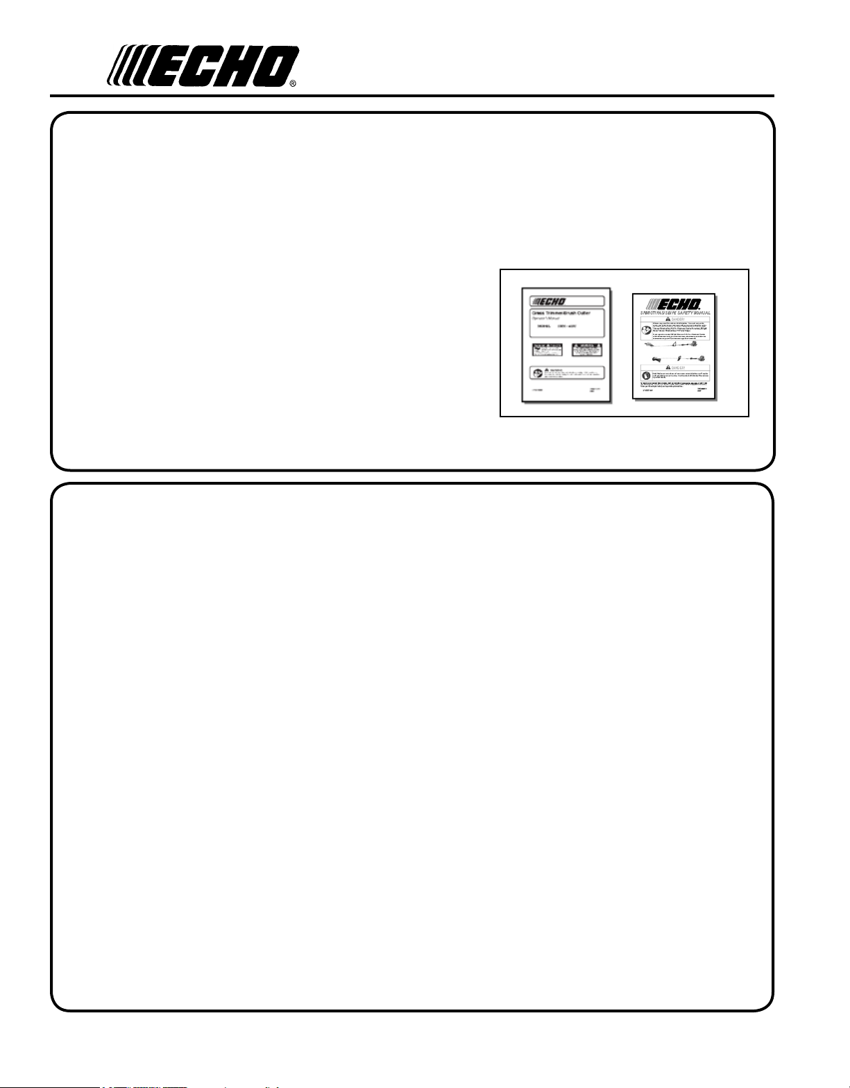
t h e o p e r a t o r 's m a n u a l
Read and understand this manual before operation. Keep it in a safe
place for future reference. Contains specications and information
for operation, starting, stopping, maintenance, storage and assembly
specic to this product.
t h e s a f e t y m a n u a l
Read and understand this manual before operation. Keep it in a safe
place for future reference. Explains possible hazards involved with
the use of Grass Trimmers and Brush Cutters and what measures you
should take to make their use safer.
ta b l e o f co n t e n t s
Introduction ..........................................................................2
- The Operator's Manual .................................................2
- The Safety manual .......................................................2
Safety ...................................................................................3
- Manual Safety Symbols and Important Information ...3
- International Symbols ..................................................3
- Personal Condition and Safety Equipment ..................3
Emission Control .................................................................6
Description ...........................................................................7
Contents ...............................................................................9
Assembly............................................................................10
- Drive Shaft / Power Head .........................................10
- Blade Installation .......................................................10
- U-Handle Installation .................................................12
- Balance and Adjust Unit ............................................13
- Optional Nylon Head Installation ..............................14
- Operating Instructions Nylon Line ............................15
Operation ............................................................................16
- Blade Selection ..........................................................16
- Fuel ............................................................................18
- Starting Cold Engine ..................................................20
- Starting Warm Engine ................................................21
- Stopping Engine .........................................................21
Maintenance .......................................................................22
- Skill Levels ................................................................22
- Maintenance Intervals ................................................22
- Air Filter .....................................................................23
- Fuel Filter ...................................................................24
- Spark Plug ..................................................................24
- Cooling System ..........................................................25
- Exhaust System ..........................................................25
- Carburetor Adjustment ...............................................27
- Lubrication .................................................................28
- Sharpening Metal Blades ...........................................29
Troubleshooting .................................................................30
Storage ...............................................................................31
Specications .....................................................................32
Specications, descriptions and illustrative material in
this literature are as accurate as known at the time of
publication, but are subject to change without notice.
Illustrations may include optional equipment and accessories, and may not include all standard equipment.
Copyright© 2009 By Echo, Incorporated
All Rights Reserved.
Page 3
sa f e t y
Gr a s s Tr i m m e r /Br u s h Cu T T e r
Op e r a T O r 's ma n u a l
3
m a n u a l
s a f e t y s y m b o l s a n d I m p o r t a n t I n f o r m a t I o n
Throughout this manual and on the product itself, you will nd safety alerts and helpful, informational messages preceded by symbols or key words. The following is an explanation of those symbols and key words and what they mean
to you.
DANGER
The safety alert symbol accompanied by the word
“DANGER” calls attention to an act or condition
which WILL lead to serious personal injury or
CIRCLE AND SLASH SYMBOL
This symbol means the specic action
shown is prohibited. Ignoring these prohibitions can result in serious or fatal injury.
death if not avoided.
WARNING
The safety alert symbol accompanied by the word
“WARNING” calls attention to an act or condi-
NOTE
This enclosed message provides tips for use, care and
maintenance of the unit.
tion which CAN lead to serious personal injury or
death if not avoided.
IMPORTANT
The enclosed message provides information neces-
CAUTION
sary for the protection of the unit.
The safety alert symbol accompanied by the word
“CAUTION” calls attention to an act or condition
which may lead to minor or moderate personal
injury if not avoided.
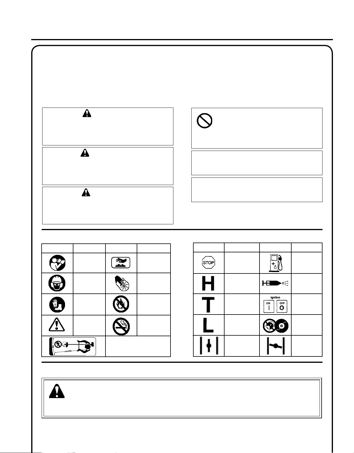
I n t e r n a t I o n a l s y m b o l s
DESCRIPTION
"WARNING, SEE OP-
ERATOR'S MANUAL
Wear eye, ear
and head protec-
tion
Wear hand and
foot protection
Safety/Alert
SYMBOLSYMBOL
Keep bystanders and helpers
away 15 m (50 ft.).
DESCRIPTION
Hot
Surface
Finger Severing
DO NOT allow
ames or sparks
near fuel.
DO NOT smoke
near fuel.
SYMBOL
DESCRIPTION
Emergency
Stop
Carburetor Adjust-
ment
- High speed
mixture
Carburetor Adjust-
ment
- Idle speed
Carburetor Adjust-
ment
- Low speed
mixture
Choke Control
"Run"
Position
(Choke Open)
SYMBOL
p e r s o n a l c o n d I t I o n a n d s a f e t y e q u I p m e n t
WARNING
Users of this product risk injury to themselves and others if the unit is used improperly and/or safety precautions
are not followed. Proper clothing and safety gear must be worn when operating unit.
DESCRIPTION
Fuel and oil
mixture
Primer
Bulb
Ignition
ON/
OFF
Do not use
blades. String
line only
Choke Control
"Cold Start"
Position
(Choke Closed)
Page 4
4
Physical Condition
Your judgment and physical dexterity may not be good:
• if you are tired or sick,
• if you are taking medication,
• if you have taken alcohol or drugs.
Operate unit only if you are physically and mentally well.
Eye Protection
Wear eye protection that meets ANSI Z87.1 or CE requirements whenever you operate the unit.
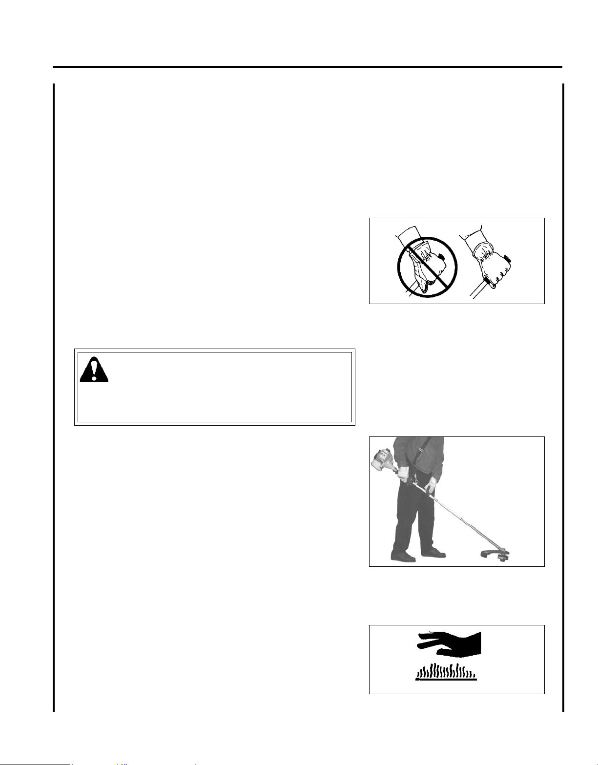
Hand Protection
Wear no-slip, heavy-duty work gloves to improve your grip on the handle. Gloves also reduce the transmission of machine vibration to your hands.
Hearing Protection
ECHO recommends wearing hearing protection whenever unit is used.
Proper Clothing
Wear snug tting, durable clothing;
• Pants should have long legs, shirts with long sleeves.
• DO NOT WEAR SHORTS,
• DO NOT WEAR TIES, SCARFS, JEWELRY.
Wear protective hair covering to contain long hair.
Wear sturdy work shoes with nonskid soles;
• DO NOT WEAR OPEN TOED SHOES,
• DO NOT OPERATE UNIT BAREFOOTED.
Keep long hair away from engine and air intake. Retain hair with cap or net.
Hot Humid Weather
Heavy protective clothing can increase operator fatigue which may lead to heat stroke. Schedule heavy work for early
morning or late afternoon hours when temperatures are cooler.
Extended Operation/Extreme Conditions
It is believed that a condition called Raynaud’s Phenomenon, which affects the ngers of certain individuals, may be
brought about by exposure to vibration and cold. Exposure to vibration and cold may cause tingling and burning sensa-
tions, followed by loss of color and numbness in the ngers. The following precautions are strongly recommended,
because the minimum exposure, which might trigger the ailment, is unknown.
• Keep your body warm, especially the head, neck, feet, ankles, hands,
and wrists.
• Maintain good blood circulation by performing vigorous arm exercises during frequent work breaks, and also by not smoking.
• Limit the hours of operation. Try to ll each day with jobs where operating the unit or other hand-held power equipment is not required.
• If you experience discomfort, redness, and swelling of the ngers followed by whitening and loss of feeling, consult your physician before
further exposing yourself to cold and vibration.
Page 5
Gr a s s Tr i m m e r /Br u s h Cu T T e r
Op e r a T O r 's ma n u a l
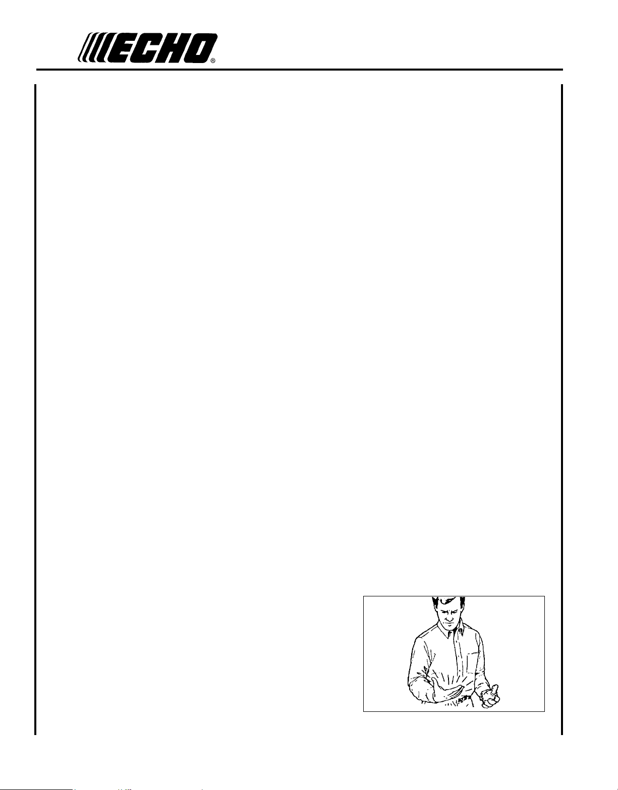
Repetitive Stress Injuries
It is believed that overusing the muscles and tendons of the ngers, hands, arms, and shoulders may cause soreness,
swelling, numbness, weakness, and extreme pain in those areas. Certain repetitive hand activities may put you at a high
risk for developing a Repetitive Stress Injury (RSI). An extreme RSI condition is Carpal Tunnel Syndrome (CTS), which
could occur when your wrist swells and squeezes a vital nerve that runs through the area. Some believe that prolonged
exposure to vibration may contribute to CTS. CTS can cause severe pain for months or even years.
To reduce the risk of RSI/CTS, do the following:
• Avoid using your wrist in a bent, extended, or twisted position.
Instead try to maintain a straight wrist position. Also, when grasping,
use your whole hand, not just the thumb and index nger.
• Take periodic breaks to minimize repetition and rest your hands.
• Reduce the speed and force with which you do the repetitive move-
ment.
• Do exercise to strengthen the hand and arm muscles.
• Immediately stop using all power equipment and consult a doctor if
you feel tingling, numbness, or pain in the ngers, hands, wrists, or
arms. The sooner RSI/CTS is diagnosed, the more likely permanent
nerve and muscle damage can be prevented.
5
DANGER
Do not operate this product indoors or in inadequately ventilated
areas. Engine exhaust contains poisonous emissions and can cause
serious injury or death.
Read the Manuals
• Provide all users of this equipment with the Operator’s Manual and
Safety Manual for instructions on Safe Operation.
Clear the Work Area
• Spectators and fellow workers must be warned, and children and
animals prevented from coming nearer than 15 m (50 ft.) while the
unit is in use.
Keep a Firm Grip
• Hold the front and rear handles with both hands, with thumbs and
ngers encircling the handles.
Keep a Solid Stance
• Maintain footing and balance at all times. Do not stand on slippery,
uneven or unstable surfaces. Do not work in odd positions or on ladders. Do not over reach.
Avoid Hot Surfaces
• Keep exhaust area clear of ammable debris. Avoid contact during
and immediately after operation.
Page 6
6
e q u I p m e n t
WARNING
Use only ECHO approved attachments. Serious injury may result from the use of a non-approved attachment combination. ECHO, INC. will not be responsible for the failure of cutting devices, attachments or accessories which
have not been tested and approved by ECHO. Read and comply with all safety instructions listed in this manual and
safety manual.
• Check unit for loose/missing nuts, bolts, and screws. Tighten and/or replace as needed.
• Inspect shield for damage and ensure that the cut-off knife is securely in place. Replace if either is damaged or miss-
ing.
• Check that the cutting attachment is rmly attached and in safe operating condition.
• Check that front loop handle and shoulder strap/ or shoulder/waist harness are adjusted for safe, comfortable opera-
tion. See Assembly Section for proper adjustment.
WARNING
Moving parts can amputate ngers or cause severe injuries. Keep hands, clothing and loose objects away from all
openings.
• ALWAYS stop engine, disconnect spark plug, and make sure all moving parts have come to a complete stop
before removing obstructions, clearing debris, or servicing unit.
• DO NOT start or operate unit unless all guards and protective covers are properly assembled to unit.
• NEVER reach into any opening while the engine is running. Moving parts may not be visible through openings.
WARNING
Check fuel system for leaks due to fuel tank damage, especially if the unit is dropped. If damage or leaks are found,
do not use unit, otherwise serious personal injury or property damage may occur. Have unit repaired by an authorized
servicing dealer before using.
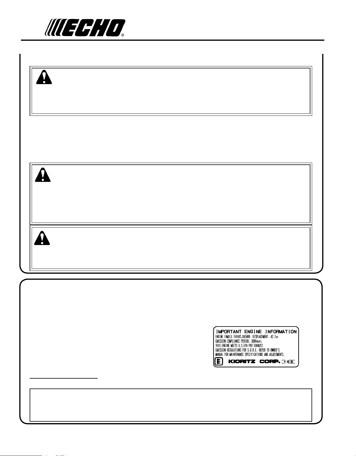
em I s s I o n co n t r o l
EPA Phase 2
The emission control system for the engine is EM (Engine Modication)
An Emission Control Label is located on the engine. (This is an EXAMPLE ONLY, information on label varies by
engine FAMILY).
PRODUCT EMISSION DURABILITY (E
The 300 hour emission compliance period is the time span selected by the manufacturer certifying the engine emissions output meets applicable emissions regulations, provided that approved maintenance procedures are followed as
listed in the Maintenance Section of this manual.
M I S S I O N CO M P L I A N C E PE R I O D )
Page 7
Gr a s s Tr i m m e r /Br u s h Cu T T e r
Op e r a T O r 's ma n u a l
7
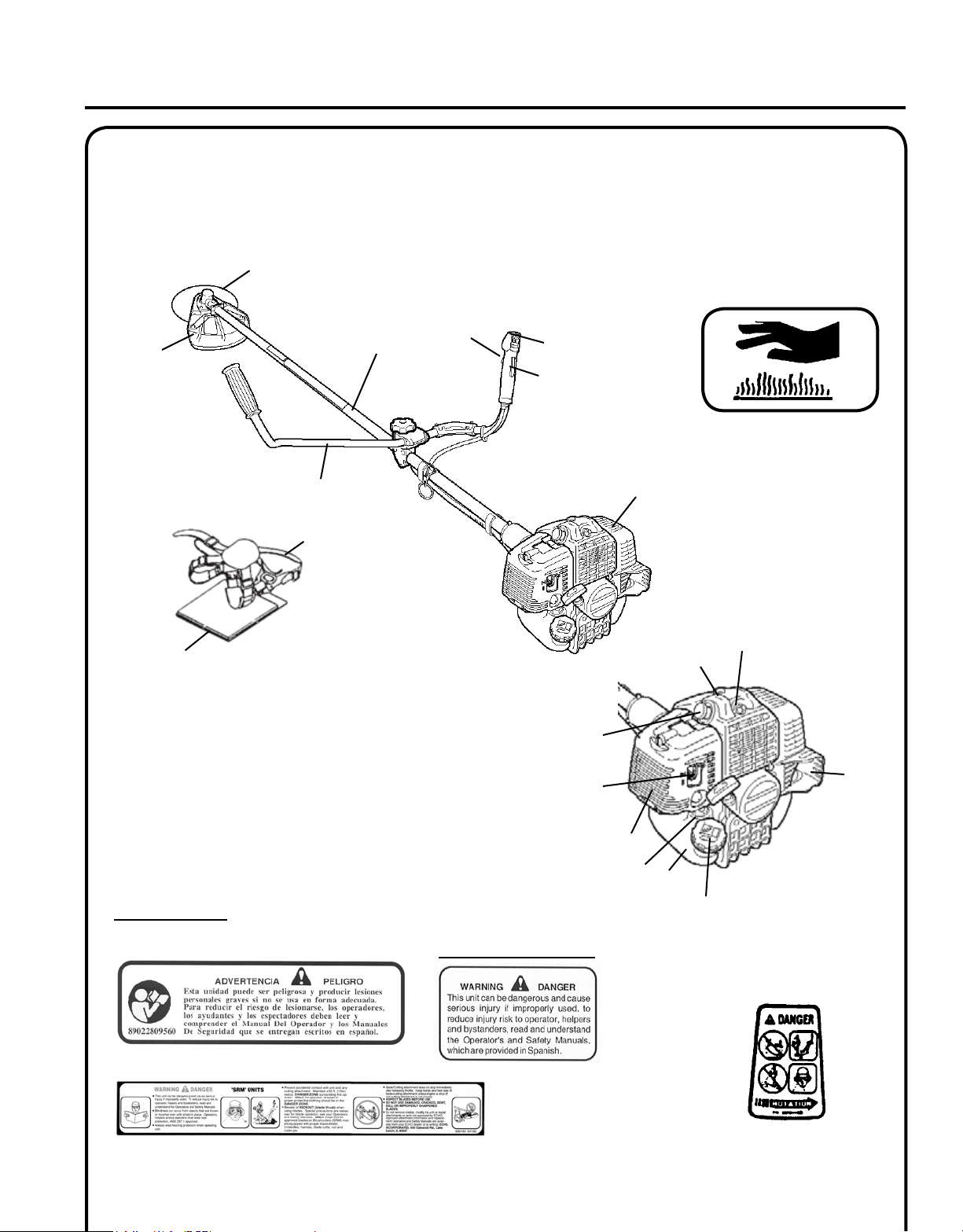
de s c r I p t I o n
Locate these safety decals on your unit. Make sure the decals are legible and that you understand and follow the instructions on them. If a decal cannot be read, a new one can be ordered from your ECHO dealer. See PARTS ORDERING
instructions for specic information.
10
9
5
6
8
7
4
3
2
1
15
Hot Decal (near mufer)
P/N X505002310
20
12
Shaft Decal
Spanish Decal
P/N 89017751830
P/N 89016054130
English Translation
11
19
18
17
14
16
Metal Debris Shield Decal
P/N 89011841031
13
Page 8

8
1. POWER HEAD - Includes the Engine, Clutch, Fuel System, Ignition System and Recoil Starter.
2. THROTTLE TRIGGER LOCKOUT - This lever must be held during starting. Operation of the throttle trigger is
prevented unless throttle trigger lockout lever is engaged.
3. STOP SWITCH - "SLIDE SWITCH" mounted on top of the Throttle Trigger Housing. Move switch FORWARD
to RUN, BACK to STOP.
4. THROTTLE TRIGGER - Controls engine speed. Spring loaded to return to idle when released. During accelera-
tion, press trigger gradually for best operating technique.
5. DRIVE SHAFT ASSEMBLY - Includes the Rear (right hand) Handle assembly, Gear Housing assembly, Front
(loop, left hand) Handle assembly, metal drive shaft and Safety Decal.
6. U-HANDLE - Required for metal blade operation.
7. HIP PAD - Used to protect hip/leg and clothing when using U-handle equipped unit.
8. SHOULDER HARNESS- An adjustable strap that suspends the unit from the operator. Using the strap reduces
operator fatigue.
9. BLADE - Circular blade for grass, weed or brush cutting applications. Harness, metal shield & U-handles required
for blade operation.
10. METAL BLADE SHIELD - Required when unit is equipped with blades. Do not operate unit without shield.
11. SPARK PLUG - Provides spark to ignite fuel mixture.
12. ARM REST - Provides arm rest during operation and protects arm from the hot engine.
13. SPARK ARRESTOR MUFFLER OR SPARK ARRESTOR MUFFLER WITH CATALYST -The mufer or
catalytic mufer controls exhaust noise and emission. The spark arrestor screen prevents hot, glowing particles of
carbon from leaving the mufer. Keep exhaust area clear of ammable debris.
14. FUEL TANK - Contains fuel and fuel lter.
15. RECOIL STARTER HANDLE - Pull handle slowly until starter engages, then quickly and rmly. When engine
starts, return handle slowly. DO NOT let handle snap back or damage to unit will occur.
16. FUEL TANK CAP - Covers and seals fuel tank opening.
17. PURGE BULB - Pumping purge bulb before starting engine draws fresh fuel from the fuel tank, purging air from
the carburetor. Pump purge bulb until fuel is visible and ows freely in the clear fuel tank return line. Pump purge
bulb an additional 4 or 5 times.
18. AIR CLEANER - Contains replaceable lter element.
19. CHOKE - The choke control is located at the rear of the air cleaner housing. Move choke lever to Cold Start
( ) to close choke for cold start. Move choke lever to "Run" ( ) position to open choke.
20. DECOMPRESSION BUTTON - Push button to assist starting. Automatically resets after engine starts and runs.
Page 9
Gr a s s Tr i m m e r /Br u s h Cu T T e r
1
EPA 2009 AND LATER / CALIFORNIA TIER III
EMISSION CONTROL WARRANTY STATEMENT
YOUR WARRANTY RIGHTS AND OBLIGATIONS
The Environmental Protection Agency (EPA) and the California Air Resources Board (C.A.R.B.) and ECHO
Incorporated are pleased to explain the emission control system warranty (exhaust and evaporative) on your EPA
2009 and later / C.A.R.B. Tier III equipment/small off road engine (SOREs). New equipment/small off road engines
must be designed, built and equipped to meet stringent EPA and C.A.R.B. anti-smog standards. ECHO Incorporated
must warrant the emission control system on your equipment/small off road engine for the periods of time listed
below, provided there has been no abuse, neglect or improper maintenance of your equipment/small off road
engine. The Emission Control System warranty is extended to the original owner including all subsequent owners.
Your emission control system may include parts such as: carburetor, fuel injected system, ignition system, catalytic
converter, fuel tank, fuel lines, fuel caps, valves, canisters, filters, vapor hoses, clamps, connectors, and other
associated components.
Where a warrantable condition exists, ECHO Incorporated will repair your equipment/small off road engine at no
cost to you including diagnosis, parts and labor.
MANUFACTURER’S WARRANTY COVERAGE:
The 2009 and later equipment/small off road engines are warranted for 5 years residential use or 2 years commercial
use for certain emission related parts. Defective parts will be repaired or replaced by ECHO Incorporated or its
Authorized Service Representative.
OWNER’S WARRANTY RESPONSIBILITIES:
•As the equipment/small off road engine owner, you are responsible for the performance of the required
maintenance listed in your Operator’s Manual. ECHO Incorporated recommends that you retain all receipts
covering ma inte nan ce o n you r eq uip ment /sm all off r oad engi ne h owe ver, E CHO Inc orpo rat ed c anno t de ny w arra nty
solely for the lack of receipts or for your failure to ensure the performance of all scheduled maintenance.
•As the equipment/small off road engine owner, you should be aware that ECHO Incorporated may deny you
warranty coverage if your equipment/small off road engine or a part has failed due to abuse, neglect, improper
maintenance or unapproved modifications.
•You are responsible for presenting your equipment/small off road engine to an ECHO Incorporated authorized
service representative as soon as a problem exists. The warranty repairs should be completed in a reasonable
amount of time, not to exceed 30 days. Should you require assistance or have questions concerning EC HO’s
Warranty Statement, you can contact our Consumer Product Support Department at 1-800-673-1558 or contact us
through the web at
WWW.ECHO-USA.COM.
For the name and address of an Authorized ECHO Dealer near you call: 1-800-432-ECHO or
WWW.ECHO-USA.COM.
X7562 0 9 0 500
01/09
Op e r a T O r 's ma n u a l
co n t e n t s
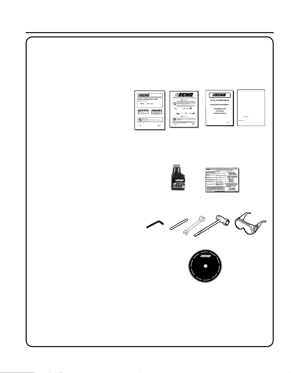
The ECHO product you purchased has been factory pre-assembled for your convenience. Due to packaging restrictions,
shield installation and other assembly may be necessary.
After opening the carton, check for damage. Immediately notify your retailer or ECHO Dealer of damaged or missing
parts. Use the contents list to check for missing parts.
___ 1- Power Head
___ 1- Drive Shaft Assembly
___ 1- Plastic Bag (co-pack)
__ - 1, Operator's Manual
__ - 1, Safety Manual
__ - 1, Warranty Registration Card
___ - 1, Limited Warranty Statement
___ - 1, Emission Control Warranty Statement
___ - 1, Tool Bag
___ --1, wrench 17x19
___ --1, locking tool
___ --1, 8 x 10mm Open End Wrench
___ --1, 4mm Hexagon Wrench
___ - 1, Safety Glasses
___ - 1,
___ - 1, Plastic Bag
___ --3, 5mm x 10mm screws (shield mount)
___ --2, 5mm x 8mm screws (bracket to shield)
___ --4, 5mm nuts
___ --4, 5mm lockwashers
___ --1, metal shield
___ --1, bracket
___ - 1, Shoulder Harness w/hip pad
___ - 10, Cotter Pins
____ - 1, Blade
Echo Power Blend X TM 2-stroke oil sample
9
Page 10
10
as s e m b l y
d r I v e
Tools Required: 4 mm Hex Wrench
Parts Required: Power Head, Drive Shaft Assembly
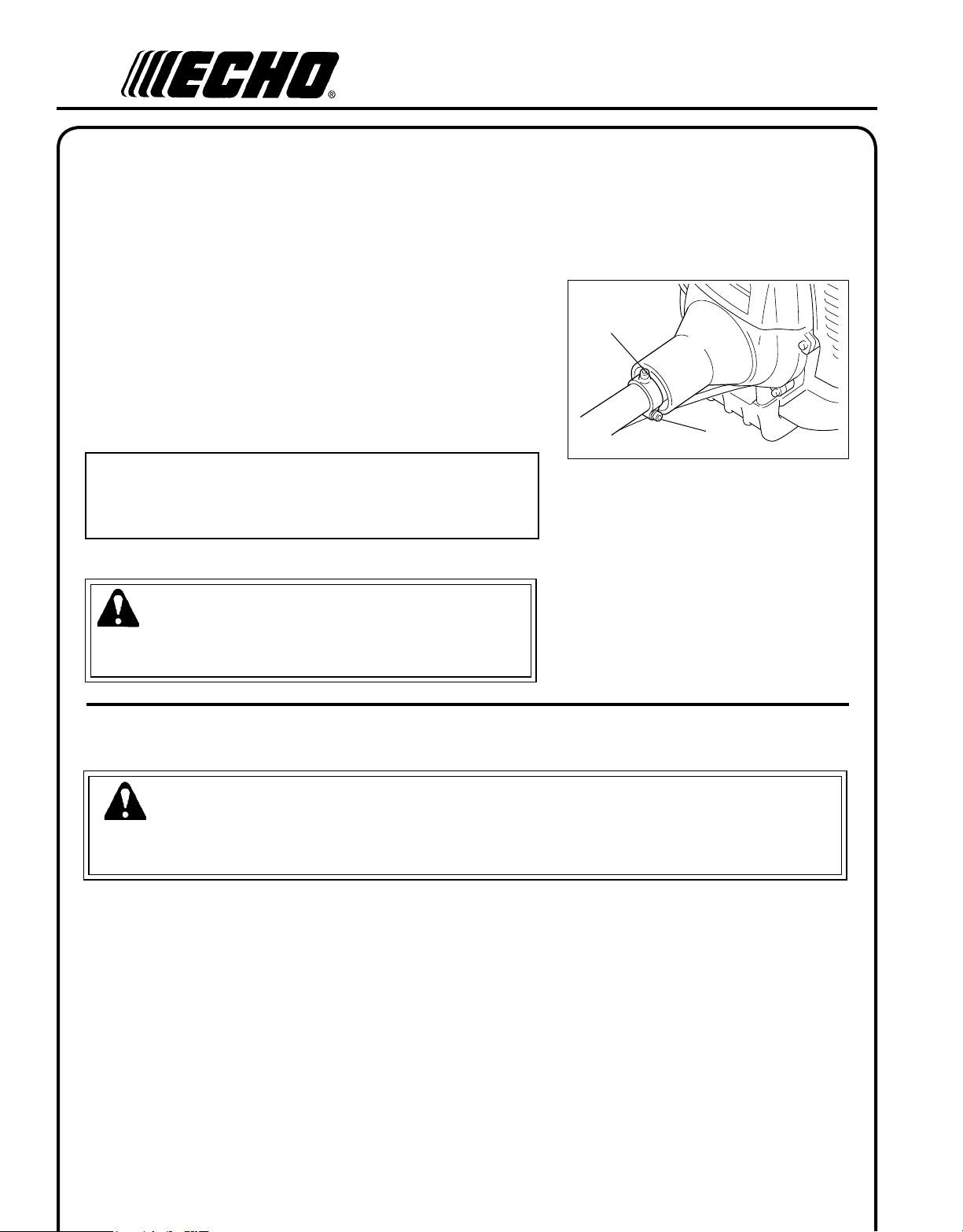
1. Stand power head upright on a level surface.
2. Loosen the drive shaft clamp bolt (A) at engine drive shaft clamp,
3. Remove protective plastic cap from end of drive shaft assembly.
4. Turn drive shaft housing until locating hole lines up with locating
5. Tighten drive shaft clamp bolt (A) securely.
s h a f t /p o w e r h e a d
and remove drive shaft locating bolt (B).
Carefully t driveshaft assembly to engine making sure that
inner drive shaft engages clutch mount.
hole in clamp and install drive shaft locating bolt (B).
NOTE
Gear housing must be aligned properly with engine. Aligning center
locating hole in driveshaft housing with center drive shaft bolt (B)
provides correct alignment.
WARNING
Never start engine without driveshaft assembly installed.
this could result in serious injury.
B
A
b l a d e I n s t a l l a t I o n
WARNING
You must install the U-Handle and all Blade Conversion parts shown in the following instructions before operating
this unit with a metal blade, otherwise serious injury may result.
Install Metal Shield
Tools Required: 8 x 10 mm Open-end Wrench, Screwdriver, 17x19
mm Wrench, Locking Tool
Parts Required: Metal Shield, Shield Bracket,
3 - 5 x 10 mm screws w/captivated at and lock-
washer, (metal shield to gear housing).
2 - 5 x 8 mm screws, 2 - 5 mm nuts, 2 - 5 mm lock-
washers, (bracket to shield).
2 - 5 mm nuts, 2 - 5 mm lockwashers
(bracket to gear housing)
Page 11
Gr a s s Tr i m m e r /Br u s h Cu T T e r
Op e r a T O r 's ma n u a l
11
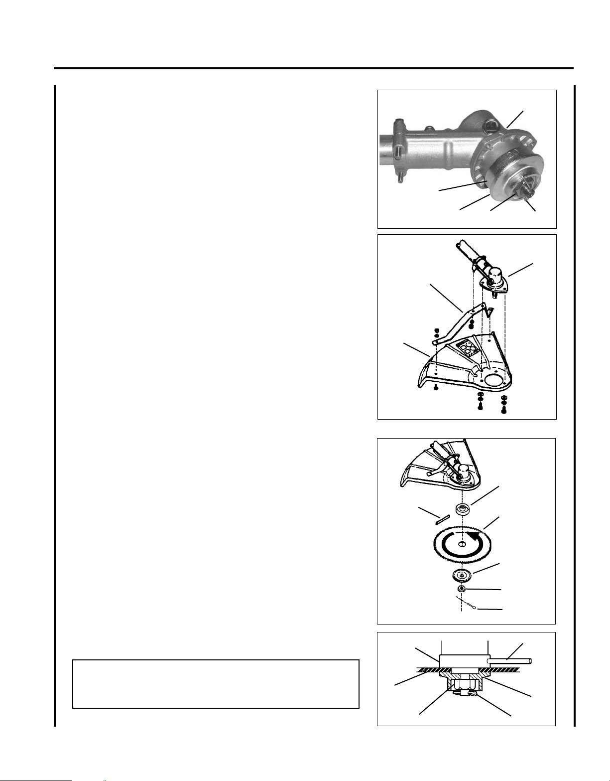
1. Align hole in upper plate (D) with notch in gear housing (E), and
insert locking tool to prevent splined shaft from turning. Arrow on
gear housing ange points to notch location.
2. Remove split pin (F), L.H. blade nut (G), lower plate (H), and upper plate (D) from PTO shaft. Turn blade nut clockwise to remove.
3. Remove locking tool.
4. Loosely attach bracket (I) to shield (J) and attach shield to bottom
of gear housing (E) with hardware provided.
5. Tighten all shield hardware.
E
D
H
I
J
G
F
E
Install Blade
Tools Required: Locking Tool, 17x19 mm Wrench.
Parts Required: Upper Plat, Lower Plate, 10 mm Nut w/L.H. threads,
2 x 25 mm Cotter Pin, Blade.
1. Install upper plate (D) on splined PTO shaft, pilot side down.
Blade installation requires Upper Plate (D).
2. Install Blade (K) on upper plate pilot. Blades must be installed so
that rotation arrow on blade matches rotation of unit: teeth toward
direction of rotation (See debris shield decal). Secure blade with
Lower Plate (H), and 10 mm L.H. nut (G). Turn nut counter-clockwise on PTO shaft to tighten.
3. Align hole in upper plate with notch in gear housing, and insert
Locking Tool (L) to prevent splined shaft from turning. Arrow on
gear housing points to notch. Tighten 10 mm nut securely.
4. Insert Cotter Pin (F) in hole in PTO shaft, and bend pin legs around
shaft counterclockwise to retain 10 mm nut.
IMPORTANT
Never reuse a cotter pin - install a new cotter pin each time a blade
is installed or replaced.
5. Remove locking tool.
D
L
D
20
K
G
K
H
G
F
L
H
F
Page 12

12
u-h a n d l e I n s t a l l a t I o n
Tools Required: 17 & 19 mm wrench, 4 mm hex wrench
Parts Required: U-Handle, Clamp w/screws, 8 mm x 55 mm hex
bolt,
8 mm at washer
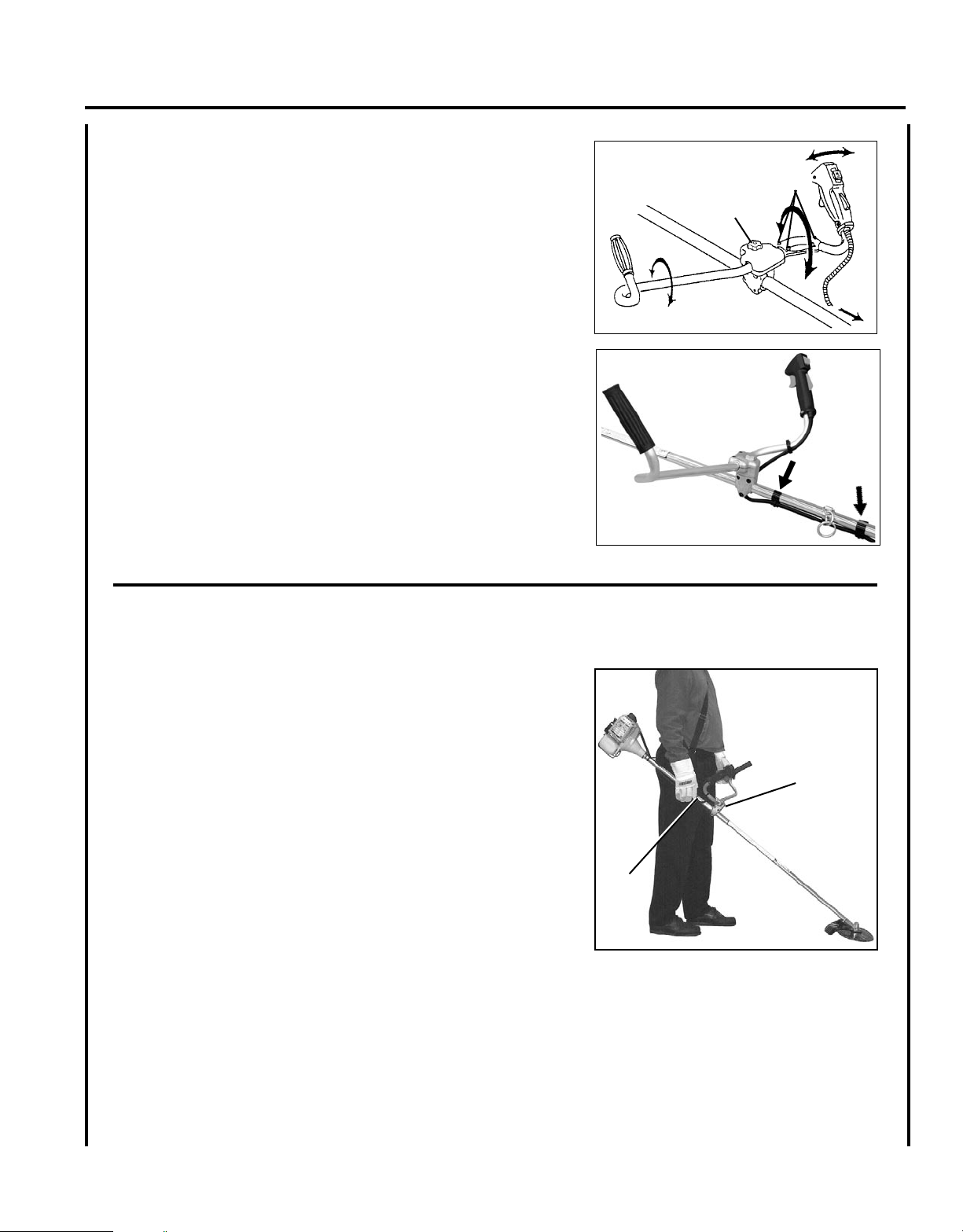
1. Remove assembling bolt (A) from right hand grip. Install right
hand grip (B) onto right hand U-handle (C) until bolt hole in Uhandle is visible through bolt hole in bottom of grip. Grip should
not rotate on handle.
2. Install assembling bolt to secure grip onto U-handle.
3. Remove bolt retainer tube (D) from end of handle assembling bolt
(E).
A
B
C
E
4. Install handle assembling bracket (upper) (F) in handle assembling
bracket (lower) (G) and secure handle by tightening handle assembling bolt (E) loosely.
5. Loosen 4 right handle assembling bolts (H) and insert right hand
U-handle (C) into right handle assembling bracket (I). (toward
direction of arrow
).
D
E
G
F
H
I
C
Page 13
Gr a s s Tr i m m e r /Br u s h Cu T T e r
6. Secure the right hand U-handle by tightening 4 right handle assembling bolts (H) loosely.
7. Adjust handles for comfortable operation and tighten handle assembling bolt (E) and 4 right handle assembling bolts (H).
8. Route throttle linkage and ignition lead assembly along shaft and
clip as shown.
Op e r a T O r 's ma n u a l
H
E
13
b a l a n c e a n d a d j u s t u n I t
1. Loosen harness clamp screw.
2. Put on harness and attach unit to harness.
3. Slide harness clamp up (A) or down until unit balances with head
approximately 50-75 mm (2 -3 in.) from the ground.
4. Tighten harness clamp screw.
5. Loosen upper U-Handle clamp screws (B), and position U-Handle
for comfortable operation.
6. Tighten U-Handle clamp screws and 8 mm clamp bolt securely.
B
A
Page 14

14
1C
1D
HOUSING
BOLT
SPRING
KNOB
1B
2A
15 cm (6 in)
SPOOL
2B
o p t I o n a l n y l o n h e a d I n s t a l l a t I o n
Tools Required: Locking Tool
Parts Required: Nylon Line Head.
1. Align hole in upper plate with notch in gear housing, and insert
locking tool to prevent splined shaft from turning.
2. Thread line head onto PTO shaft by turning it counter-clockwise
until head is tight against upper plate.
3. Remove locking tool.
• Read the Operator’s Manual carefully. Be thoroughly familiar
with the controls and proper use of the trimmer.
Know how to stop the unit and disengage the controls.
• Never allow children to operate the trimmer.
• Never allow adults to use the trimmer unless they have received
proper instructions. Be sure the operator is properly attired and
wears the type of foot, leg, head, eye and ear protection recommended both in your ECHO Operator’s Manual and by your
ECHO Servicing Dealer.
• Always wear eye protection that conforms to ANSI Z 87.
1-2000.1. Read the Operator’s Manual carefully. Be thoroughly
familiar with the controls and proper use of the trimmer.
Know how to stop the unit and disengage the controls.
WARNING
Grass/weed trimmers can throw gravel, stone, wood chips, glass,
and plastic or metal objects. The debris shield behind the trimmer
head stops much of the debris, but cannot prevent the operator from
being struck by some debris. Read the rules for safe operation in the
operator’s manual that you received with your echo trimmer. Also,
follow all instructions in this instruction sheet.
1. REPLACING LINE
A. Remove spool by turning knob clockwise, “right”, and separating
parts.
B. Thread a 6 m (20 feet) length of 2.4 mm (0.095 in) or 2.7 mm
(0.105 in) ECHO line through hole in spool so that ends are the
same length.
C. Wind both ends of line tightly and evenly clockwise (see arrows on
spool), and wind from side to side without twisting the lines.
D. Secure ends of line temporarily with about 15 cm (6 in) extending
out.
Page 15
Gr a s s Tr i m m e r /Br u s h Cu T T e r
CUTTING PROCEDURES
Locking tool
Upper fixing plate
TIGHTEN
Cutting head
2.REPLACING SPOOL
NOTE
Keep line tight on spool.
A. Snap spool into housing while pulling line through eyelets with
about 15 cm (6 in) extending out.
CAUTION
Knob tightens counterclockwise, “left”.
B. Fasten spool to housing with shaft bolt, spring, and knob.
o p e r a t I n g I n s t r u c t I o n s n y l o n l I n e
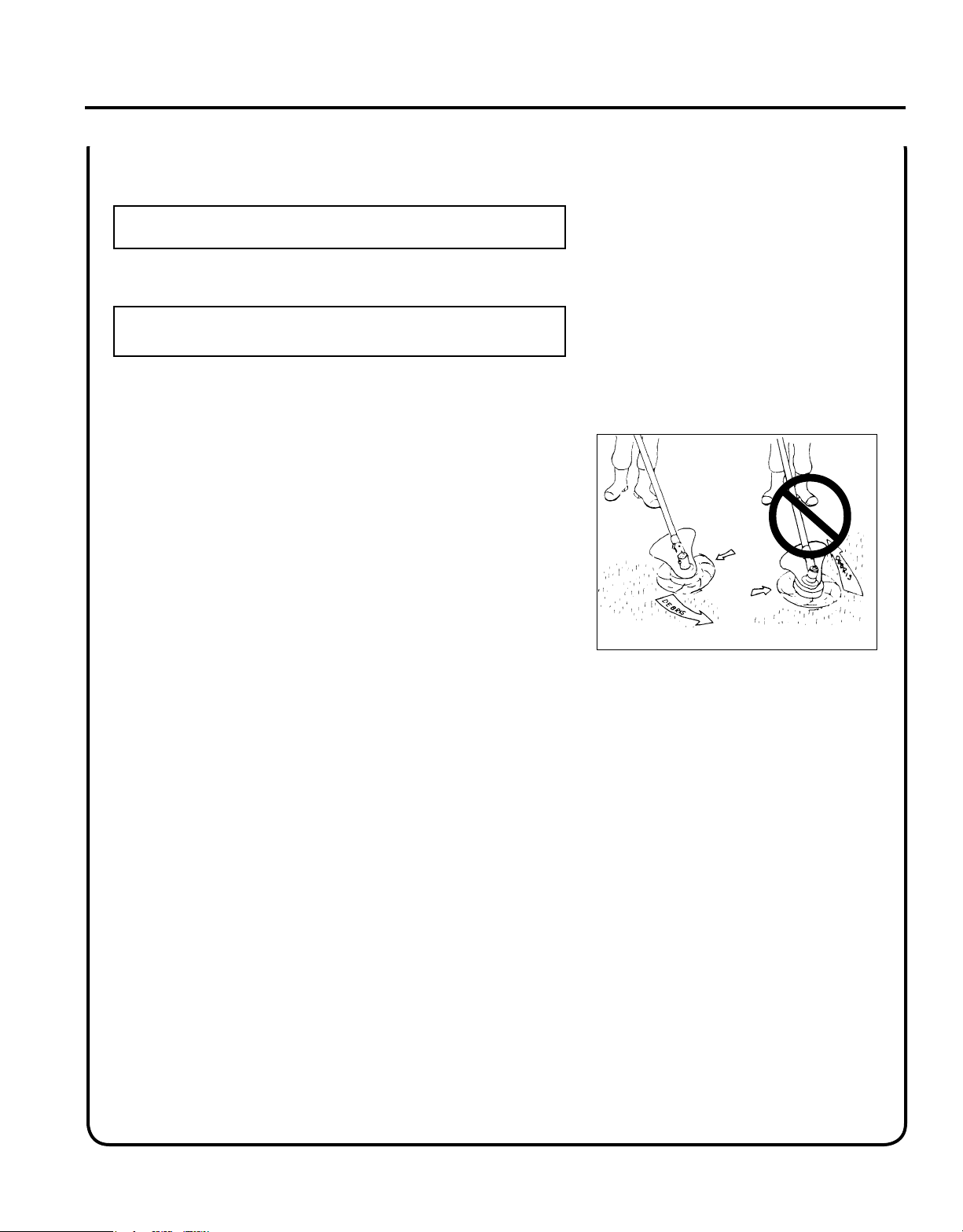
1. Always use the end of the line for cutting. Forcing the cutter head
too close to the work will result in reduced efciency and broken
line.
2. Maintain the line at the recommended length of 12.5 to 15 cm (5
to 6 in). A longer line will reduce engine speed, a shorter line may
result in engine damage.
3. The trimmer head rotates counterclockwise. Always cut with the
head tilted to the right to deect debris away from the operator.
4. Always observe the SAFETY RULES on Page 5 when using the
unit.
Op e r a T O r 's ma n u a l
15
Page 16

16
SRM/PAS/SB BLADE SET-UP GUIDE*
TO USE
THESE BLADES
Pro Maxi-Cut
Grass/Weed
Plastic Cutters
Rigid Plastic
Tri-Cut
Grass/Weed Blade
Metal
Tri-Cut/8 Tooth
Grass/Weed Blade
Metal 80T Brush Blade
Metal 22T Clearing Saw Blade
Handle
Loop Handle, w/or
w/o Barrier Bar
Loop Handle
w/Barrier Bar,
or U-Handle
Loop Handle
w/Barrier Bar,
or U-Handle
U-Handle
Debris Shield Metal Shield Metal Shield Metal Shield Metal Shield
Harness Shoulder Harness Shoulder Harness Shoulder Harness Shoulder Harness****
Upper Plate &
Flat Washer
Upper Plate
& Glide Cup
Upper/Lower
Blade Plates**
Upper/Lower
Blade Plates**
Hex Nut Hex Nut Hex Nut Hex Nut
You
must
install
these
parts!
Blade
Mounting
Hardware
New Cotter Pin*** New Cotter Pin*** New Cotter Pin*** New Cotter Pin***
* WARNING! DO NOT INSTALL BLADES ON GT (CURVED SHAFT) MODEL TRIMMERS
** Arbor diameter of Upper Blade Plate must match arbor diameter of metal blades.
*** New cotter pin required each time blade is installed.
**** Brushcutters over 16.5 lbs (7.5 kg) dry weight (weight w/o fuel) require a double shoulder harness
op e r a t I o n
WARNING
Moving parts can amputate ngers or cause severe injuries. Keep hands, clothing and loose objects away from all
openings. Always stop engine, disconnect spark plug, and make sure all moving parts have come to a complete
stop before removing obstructions, clearing debris, or servicing unit.
WARNING
Engine exhaust IS HOT, and contains Carbon Monoxide (CO), a poison gas. Breathing CO can cause unconsciousness, serious injury, or death. Exhaust can cause serious burns. ALWAYS position unit so that exhaust is directed
away from your face and body.
WARNING
Operation of this equipment may create sparks that can start res around dry vegetation. This unit is equipped with
a spark arrestor and a spark arrestor may be required. The operator should contact local re agencies for laws or
regulations relating to re prevention requirements.
b l a d e s e l e c t I o n
WARNING
The type of Blade used MUST be matched to the type and size of material cut. An improper or dull blade can cause
serious personal injury. Blades MUST be sharp. Dull blades increase the chance of kick-out and injury to yourself
and bystanders.
Page 17

Gr a s s Tr i m m e r /Br u s h Cu T T e r
Plastic/Nylon Grass/Weed Blades may be used where ever the nylon
line head is used. DO NOT use this blade for heavy weeds or brush!
8 Tooth Weed/Grass Blade is designed for grass, garden debris
and thick weeds. DO NOT use this blade for brush or heavy woody
growth, 19 mm (3/4 in.) diameter or larger.
Op e r a T O r 's ma n u a l
17
80 Tooth Brush Blade is designed for cutting brush and woody growth
up to 13mm (3 in.) diameter.
22 Tooth Clearing Blade is designed for dense thickets and saplings
up to 64 mm (3 in.) diameter.
Use Shoulder/Waist Harness Use of the Shoulder/Waist Harness is
recommended for ALL Trimmer/Brush Cutter use, not just Blade operation. The Shoulder/Waist Harness when used in a trimming operation
with nylon line head suspends the trimmer from the operator's shoulder
and reduces operator fatigue.
During blade operation, the same fatigue reduction is achieved. Safety
to the operator is also enhanced by reducing the possibility of blade
contact with the operator's hands and feet by restricting trimmer movement
WARNING
In case of emergency, pull the quick release latch to disconnect
the trimmer from the harness.
Page 18
18
f u e l
NOTICE: Use of unmixed, improperly mixed, or fuel older than 90 days, (stale fuel), may cause hard starting, poor
performance, or severe engine damage and void the product warranty. Read and follow instructions in the Storage
section of this manual.
WARNING
Alternative fuels, such as E-20 (20% ethanol), E-85 (85% ethanol) or any fuels not meeting ECHO requirements
are NOT approved for use in ECHO 2-stroke gasoline engines. Use of alternative fuels may cause performance
problems, loss of power, overheating, fuel vapor lock, and unintended machine operation, including, but not limited
to, improper clutch engagement. Alternative fuels may also cause premature deterioration of fuel lines, gaskets,
carburetors and other engine components.
Fuel Requirements
Gasoline - Use 89 Octane [R+M/2] (mid grade or higher) gasoline known to be good quality. Gasoline may contain up
to 10% Ethanol (grain alcohol) or 15% MTBE (methyl tertiary-butyl ether). Gasoline containing methanol (wood alcohol) is NOT approved.
Two Stroke Oil - A two-stroke engine oil meeting ISO-L-EGD (ISO/CD 13738) and J.A.S.O. FC/FD Standards must
be used. Echo brand premium Power Blend X TM Universal 2-Stroke Oil meets these standards. Engine problems due to
inadequate lubrication caused by failure to use an ISO-L-EGD (ISO/CD 13738) and J.A.S.O. FC/FD certied oil, such
as Echo premium Power Blend X TM, will void the two-stroke engine warranty.
IMPORTANT
Echo premium Power Blend X
engines sold in the past regardless of ratio specied in those manuals.
TM
Universal 2-Stroke Oil may be mixed at 50:1 ratio for application in all Echo
Handling Fuel
DANGER
Fuel is VERY ammable. Use extreme care when mixing, storing or handling or serious personal injury may result.
• Use an approved fuel container.
• DO NOT smoke near fuel.
• DO NOT allow ames or sparks near fuel.
• Fuel tanks/cans may be under pressure. Always loosen fuel caps slowly allowing pressure to equalize.
• NEVER refuel a unit when the engine is HOT or RUNNING!
• DO NOT ll fuel tanks indoors. ALWAYS ll fuel tanks outdoors over bare ground.
• DO NOT overll fuel tank. Wipe up spills immediately.
• Securely tighten fuel tank cap and close fuel container after refueling.
• Inspect for fuel leakage. If fuel leakage is found, do not start or operate unit until leakage is repaired.
• Move at least 3m (10 ft.) from refueling location before starting the engine.
Page 19

Gr a s s Tr i m m e r /Br u s h Cu T T e r
Mixing Instructions
1. Fill an approved fuel container with half of the required amount of
gasoline.
2. Add the proper amount of 2-stroke oil to gasoline.
3. Close container and shake to mix oil with gasoline.
4. Add remaining gasoline, close fuel container, and remix.
IMPORTANT
Spilled fuel is a leading cause of hydrocarbon emissions. Some
states may require the use of automatic fuel shut-off containers to
reduce fuel spillage.
Op e r a T O r 's ma n u a l
19
After use
• DO NOT store a unit with fuel in its tank. Leaks can occur. Return
unused fuel to an approved fuel storage container.
Storage - Fuel storage laws vary by locality. Contact your local government for the laws affecting your area. As a precaution, store fuel in
an approved, airtight container. Store in a well-ventilated, unoccupied
building, away from sparks and ames.
IMPORTANT
Stored fuel ages. Do not mix more fuel than you expect to use in
thirty (30) days, ninety (90) days when a fuel stabilizer is added.
IMPORTANT
Stored two-stroke fuel may separate. ALWAYS shake fuel container thoroughly before each use.
Shoulder
level
Fuel tank
Page 20

20
s t a r t I n g c o l d e n g I n e
WARNING
When engine is started, conrm that there is not any abnormal
vibration or sound. If there is abnormal vibration or sound, ask
your DEALER to repair. After refueling tighten fuel cap rmly and
check for leakage. In case of fuel leakage repair before starting
operation since there is a danger of re.
1. Stop Switch
Move stop switch button (A) forward away from the STOP posi-
tion.
A
2. Choke
Move choke lever (B) to Cold Start Position ( ).
3. Purge Bulb
Pump purge bulb (C) until fuel is visible and ows freely in the
clear fuel tank return line. Pump bulb an additional 4 or 5 times.
4. Press the decompression device (E).
5. Recoil Starter
Lay the unit on a at area and keep movable attachment parts clear
of all obstacles. Hold unit rmly, and rapidly pull recoil starter
handle/rope (D) until engine res (or maximum ve [5] pulls).
NOTE
Starter handle : Use short pulls - only 1/2 - 2/3 of starter rope for
starting. Do not let starter rope snap back in.
Always hold the unit rmly.
6. Choke
After engine res (or 5 pulls), move choke lever back to Run
(
) position. Pull recoil starter starter handle/rope until engine
starts and runs. Allow unit to warm up at idle for several minutes.
NOTE
If engine does not start with choke in “Run” position after 5 pulls,
repeat instructions 2 - 5.
B
C
E
D
D
7. Throttle Trigger
After engine warm-up, gradually depress throttle trigger to increase
engine RPM to operating speed.
Page 21

s t a r t I n g w a r m e n g I n e
Gr a s s Tr i m m e r /Br u s h Cu T T e r
Op e r a T O r 's ma n u a l
21
1. Press the decompression device (E).
2. Stop Switch
Move stop switch button (A) forward away from the STOP posi-
tion.
3. Purge Bulb
Pump purge bulb (C) until fuel is visible in the "Clear" fuel return
line.
E
A
4. Recoil Starter
Lay the unit on a at area and keep movable attachment parts clear
of all obstacles. Hold unit rmly and rapidly pull the recoil starter
handle (D) until the engine res.
NOTE
If engine does not start after 5 pulls, use Cold Start Procedure.
s t o p p I n g e n g I n e
1. Release throttle trigger and allow to run at an idle speed.
2. Slide ignition switch to “STOP” position.
C
D
D
Page 22

22
COMPONENT/
SYSTEM
MAINTENANCE
PROCEDURE
REQ'D
SKILL
LEVEL
DAILY OR
BEFORE
USE
EVERY
REFUEL
3 MONTHS
OR 90
HOURS
YEARLY
600 HOURS
Air Filter Inspect/Clean
1 I / C * R *
Choke Shutter Inspect/Clean
1 I / C
Fuel Filter Inspect/Replace
1 I * I / R *
Fuel Cap Gasket Inspect/Replace 1
I * R
Fuel System Inspect/Replace
1 I (2) * I (2) *
Spark Plug Inspect/Clean
1 I / C / R *
Cooling System Inspect/Clean
2 I / C
Muffler Spark Arrestor Inspect/Clean/Replace
2 I / C / R *
Cylinder Exhaust Port Inspect/Clean/Decarbon
2 I / C
Gear Housing Grease
2 I (1)
Recoil Starter Rope Inspect/Clean
1 I / C *
Screws/Nuts/Bolts Inspect/Tighten/Replace
1 I *
(1) Apply POWER BLENDXTM every 50 hours of use.
(2) Low evaporative fuel tanks DO NOT require regular maintenance to maintain emission integrity.
* Replacement is recommended based on the finding of damage or wear during inspection.
MAINTENANCE PROCEDURE LETTER CODES:
I = INSPECT, R = REPLACE, C = CLEAN
IMPORTANT NOTE
- Time intervals shown are maximum. Actual use and your experience will determine the
frequency of required maintenance.
MAINTENANCE PROCEDURE NOTES:
ma I n t e n a n c e
WARNING
Moving parts can amputate ngers or cause severe injuries. Keep hands, clothing and loose objects away from all
openings. Always stop engine, disconnect spark plug, and make sure all moving parts have come to a complete
stop before removing obstructions, clearing debris, or servicing unit. Allow unit to cool before performing service.
Wear gloves to protect hands from sharp edges and hot surfaces.
Your ECHO trimmer is designed to provide many hours of trouble free service. Regular scheduled maintenance will help
your trimmer achieve that goal. If you are unsure or are not equipped with the necessary tools, you may want to take
your unit to an ECHO Service Dealer for maintenance. To help you decide whether you want to DO-IT-YOURSELF or
have the ECHO Dealer do it, each maintenance task has been graded. If the task is not listed, see your ECHO Dealer for
repairs.
s k I l l l e v e l s
Level 1 = Easy to do. Common tools may be required.
Level 2 = Moderate difculty. Some specialized tools may be required.
ECHO offers REPOWERTM Maintenance Kits and Parts to make your maintenance job easier.
m a I n t e n a n c e I n t e r v a l s
Page 23

Gr a s s Tr i m m e r /Br u s h Cu T T e r
a I r f I l t e r
Level 1.
Tools required: 25 - 50mm (1 - 2 in.) cleaning brush
Parts required: REPOWERTM Tune-Up Kit
NOTE
Always brush dirt and debris away from air cleaner area prior to
cleaning air lter.
1. Brush dirt off air cleaner area. Keep dirt away from engine and air
intake grid.
2. Remove air lter cover (A). Brush dirt from inside cover and away
from edges of air lter.
3. Check air lter seal for tight t with air lter case.
4. Remove air lter (B) from case. Use care to prevent dirt and debris
from falling into air lter case.
Op e r a T O r 's ma n u a l
B
A
23
5. Inspect lter element and seal. Replace lter if any of these problems are present:
•Air lter seal does not t tightly against case
•Air lter seal is distorted, worn, or damaged
•Air lter element has holes or other damage
•Air lter element is saturated with dirt
•Air lter element is soaked with fuel mix
6. If air lter is in good condition and can be cleaned and reused,
lightly brush debris from air lter element, or blow lter element
clean using low pressure (40 psi or less) compressed air directed at
inside of lter.
IMPORTANT
When using compressed air, always direct air stream at inside sur-
face of lter so dust and debris will be blown out of lter. Keep air
nozzle 6 - 8 inches away from lter to prevent damage to lter.
7. Install air lter in case, and replace cover.
NOTICE
Actual replacement interval for air lter depends on operating conditions. Operation in dustier applications requires more frequent
cleaning and replacement. Continued operation with a damaged
or excessively dirty lter will allow dirt and debris to enter engine,
and result in poor performance, rapid engine wear, and premature
engine failure.
Page 24

24
f u e l f I l t e r
Level 1.
Tools required: 200- 250 mm (8 - 10 in.) length of wire with one end
bent into a hook, clean rag, funnel, and an approved
fuel container.
Parts required: REPOWERTM Tune-Up Kit
DANGER
Fuel is VERY ammable. Use extreme care when mixing, storing or
handling.
1. Use a clean rag to remove loose dirt from around fuel cap and
empty fuel tank.
2. Use the “fuel line hook” to pull the fuel line and lter from the
tank.
3. Remove the lter from the line and install the new lter.
s p a r k p l u g
Level 2.
Tools Required: T-wrench, feeler gauge, soft metal brush.
Parts Required: REPOWERTM Tune-Up Kit
1. Remove spark plug and check for fouling, worn and rounded
center electrode.
2. Clean the plug or replace with a new one. DO NOT sand blast to
clean. Remaining sand will damage engine.
3. Adjust spark plug gap by bending outer electrode.
4. Install Spark Plug, and tighten to 150-170 kgf • cm
(130-150 in. • lbf).
0.6 - 0.7 mm (.024 - .028 in)
Page 25

Gr a s s Tr i m m e r /Br u s h Cu T T e r
c o o l I n g s y s t e m
Level 2.
Tools required: Air compressor and safety nozzle, or: 4 mm Hex
wrench, 25 - 50 mm (1 - 2 in.) cleaning brush.
Parts Required: None.
IMPORTANT
To maintain proper engine operating temperatures, cooling air must
pass freely through the cylinder n area. This ow of air carries
combustion heat away from the engine.
Overheating and engine seizure can occur when:
• Air intakes are blocked, preventing cooling air from reaching the
cylinder.
• Dust and debris build-up on the outside of the cylinder. This build-up
insulates the engine and prevents the heat from leaving.
Op e r a T O r 's ma n u a l
25
Removal of cooling passage blockages and cleaning of cooling ns is
considered “Normal Maintenance.” Any failure attributed to lack of
maintenance is not warranted.
1. Periodically blow dirt and debris off cooling ns with a compres-
sor and safety nozzle, or;
2. Remove engine and mufer covers, and brush off dirt and debris
using the medium bristle brush.
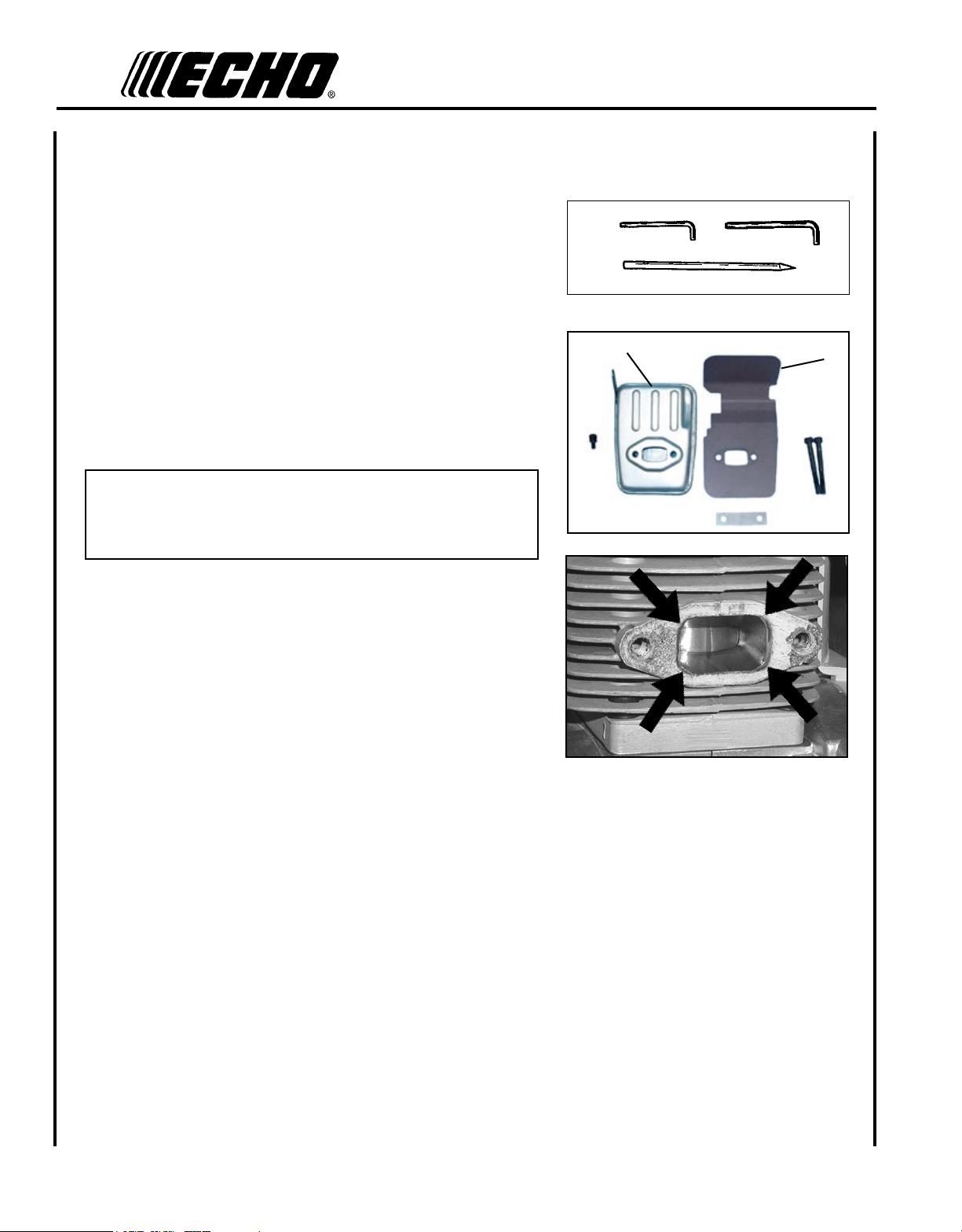
e X h a u s t s y s t e m
Spark Arrestor Screen
Level 2.
Tools Required: Cross Head Screwdriver, Soft Metal Brush, 4 mm
Hex Wrench
Parts Required: Spark Arrestor Screen, Gasket
1. Remove mufer cover (A).
2. Place piston at Top Dead Center (TDC) to prevent carbon/dirt from
entering cylinder.
A
3. Remove spark arrestor screen cover (B), screen holder (C), gasket
(D), and screen (E), from mufer body.
4. Clean carbon deposits from mufer components.
5. Replace screen if it is cracked, plugged, or has holes burned
through.
6. Assemble components in reverse order.
DE
C
B
Page 26
26
Exhaust Port Cleaning
Level 2.
Tools required: 4 & 5 mm Hex Wrench, Wood or plastic scraper
Parts Required: As needed: Heat Shield
1. Remove spark plug lead from spark plug, and remove mufer
cover (2 screws).
2. Place piston at top dead center. Remove mufer (A) and heat shield
(B).
3. Use a wood or plastic scraping tool to clean deposits from cylinder
exhaust port.
IMPORTANT
Never use a metal tool to scrape carbon from the exhaust port.
Do not scratch the cylinder or piston when cleaning the exhaust
port. Do not allow carbon particles to enter the cylinder.
A
B
4. Inspect heat shield, and replace if damaged.
5. Install heat shield and mufer.
6. Tighten mufer mounting bolts (or nuts) to 95-130 in•lbf (110-150
kgf•cm).
7. Attach spark plug lead and install mufer cover.
8. Start engine, and warm to operating temperature.
9. Stop engine, and re-tighten mounting bolts (or nuts) to specications.
Page 27
Gr a s s Tr i m m e r /Br u s h Cu T T e r
CARBURETOR ADJUSTMENT
Engine Break-In
New engines must be operated a minimum of two tanks of fuel before
carburetor adjustments can be made. During the break-in period your
engine performance will increase and exhaust emissions will stabilize.
Idle speed can be adjusted as required.
High Altitude Operation
This engine has been factory adjusted to maintain satisfactory starting,
emission, and durability performance up to 1,100 feet mean sea level
(MSL) (96.0 kPa and below). To maintain proper engine operation and
emission compliance above 1,100 feet MSL the carburetor may need to
be adjusted by an authorized ECHO service dealer.
IMPORTANT
If the engine is adjusted for operation above 1,100 feet MSL, the
carburetor must be re-adjusted when operating the engine below
1,100 feet MSL, otherwise severe engine damage can result.
Op e r a T O r 's ma n u a l
27
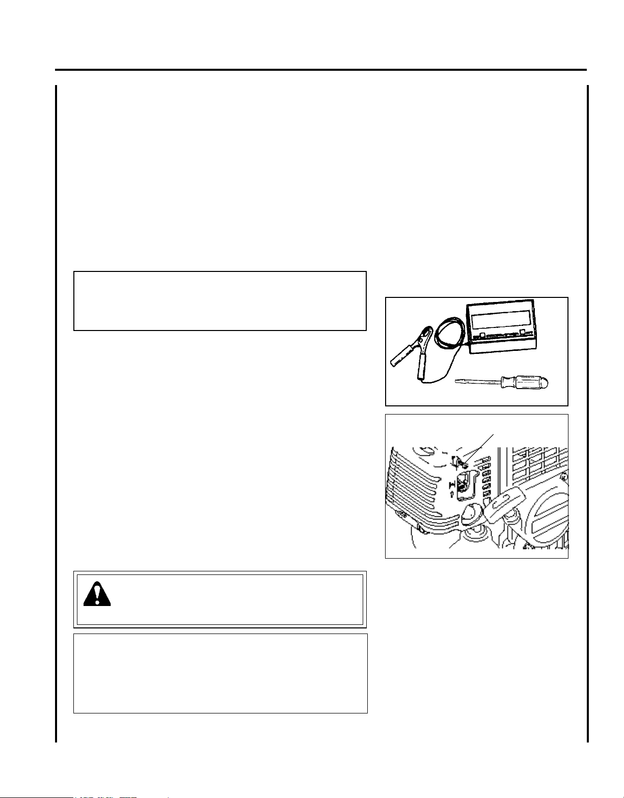
Level 2.
Tools required: Screwdriver, Tachometer (ECHO P/N 99051130017).
Parts required: None.
1. Before adjusting carburetor clean or replace air lter and mufer,
“Spark Arrestor Screen”.
2. Make sure the cutting attachment such as hedge clipper blades
or circular saw are properly adjusted. Trimmer line should be
extended to cut-off knife.
3. Start engine and run several minutes to bring to operating temperature. Flash choke twice during warm-up to clear any air from the
fuel system.
4. Idle Speed Adjustment
• Start engine, turn “idle” speed adjustment screw clockwise
(CW) until the cutting attachment begins to turn, then turn screw
out counterclockwise (CCW) until attachment stops turning. Turn
screw out, CCW, an additional 1/4 turn.
WARNING
Cutting attachment must not turn or move when unit is idling.
Idle speed adjustment screw (T)
CAUTION
When starting, idling adjustment speed should be adjusted not to
rotate the cutting attachment. Correct idle speed is adjusted 2300 to
2700 r/min. Or 1/4 turn CCW from the point the cutting attachment
stops moving. When there is some trouble with the carburetor, refer
to your dealer.
Page 28

28
l u b r I c a t I o n
Level 1.
Tools Required: 8 & 13 mm Open End Wrench, Screwdriver,
Clean Rag.
Parts Required: POWER BLENDXTM 8 oz. (P/N 91014) or Lithium
Base Grease.
Gear Housing
1. Clean all loose debris from gear box.
2. Remove plug (A) and check level of grease. Grease should ll gear
case to bottom of grease plug hole.
3. Add grease if necessary using manual grease gun or squeeze-type
tube. Do not use high pressure grease gun. DO NOT over-ll.
A
Page 29
Gr a s s Tr i m m e r /Br u s h Cu T T e r
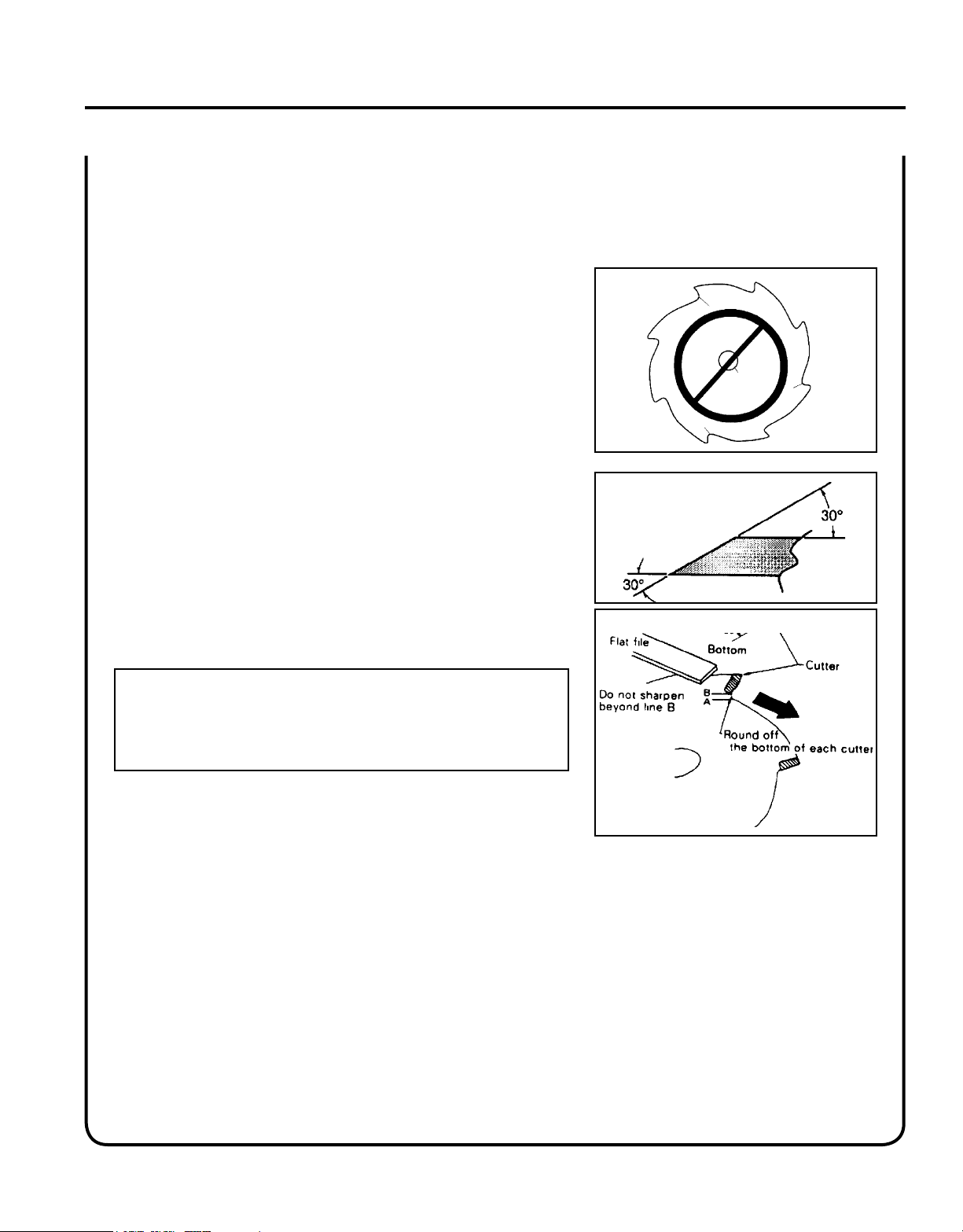
s h a r p e n I n g m e t a l b l a d e s
Three styles of metal blades are approved for use on the ECHO Brush
Cutter. The 8-tooth blade can be sharpened during normal maintenance. The clearing blade and 80 tooth blade require professional
service.
Before sharpening, CLOSELY inspect blade for cracks (look at the
bottom of each tooth and the center mounting hole closely), missing
teeth and bending. If ANY of these problems are discovered, replace
the blade.
When sharpening a blade, always remove the same amount of materials
from each tooth to maintain balance. A blade that is not balanced will
cause unsafe handling due to vibration and can result in blade failure.
Tool required: Flat le (preferred). Electric grinder if special care is
used. Round (rat tail) le for gullet (radius).
Op e r a T O r 's ma n u a l
29
1. File each tooth at a 30 degree angle a specic number of times,
eg. 4 strokes per tooth. Work your way around the blade until
all teeth are sharp.
2. DO NOT le the 'gullet' (radius) of the tooth with the at le.
The radius must remain. A sharp corner will lead to a crack and
blade failure.
IMPORTANT
If an electric grinder is used, use care not to overheat teeth, do not
allow tips/tooth to glow red or turn blue. DO NOT place blade in
cooling water. This will change the temper of the blade and could
result in blade failure.
3. After sharpening teeth, check each tooth radius for evidence of a
square (sharp) corner. Use the round (rat tail) le to renew the
radius.
Page 30

30
TRAHCGNITOOHSELBUORTMELBORPENIGNE
melborPkcehCsutatSesuaCydemeR
enignE
-sknarc
/drahstrats
t'nseod
trats
roterubractaleuFroterubractaleufoNdeggolcreniartsleuF
deggolcenilleuF
roterubraC
ecalperronaelC
ecalperronaelC
relaedohcEruoyeeS
rednilyctaleuFrednilyctaleufoNroterubraCrelaedohcEruoyeeS
leufhtiwtewrelffuMhcirooterutxiMleuFekohcnepO
retlifriaecalper/naelC
roterubractsujdA
relaedohcEruoyeeS
dnetakrapS
eriwgulpfo
krapsoNffohcti
wspotS
melborplacirtcelE
hctiwskcolretnI
NOothctiwsnruT
relaedohcEruoyeeS
relaedohcEruoyeeS
gulptakrapSkrapsoNtcerrocnipagkrapS
nobrachtiwderevoC
leufhtiwdeluoF
evitcefedgulP
).ni620.0(mm56.ottsujdA
ecalperronaelC
ecalperronaelC
gulpecalpeR
,snurenignE
roseidtub
tonseod
etarelecca
ylreporp
retlifriAytridretlifriAraewlamroNecalperronaelC
retlifleuFytridretlifleuFseudiser/stnanimatnoCni
leuf
ecalpeR
tnevleuFdeggulptnevleuFniseudise
r/stnanimatnoC
leuf
ecalperronaelC
gulPkrapSnrow/ytridgulPraewlamroNecalperrotsujdadnanaelC
roterubraCtnemtsujdareporpmInoitarbiVtsujdA
metsySgnilooCmetsysgnilooC
deggulp/ytrid
ninoitarepodednetxE
snoitacolytsud/ytrid
naelC
rotserrAkrapS
neercS
rotserrakrapS
deggulpneercs
raewlamroNecalpeR
seodenignE
knarcton
A/NA/NmelborpenignelanretnIrelaedohcEruoyeeS
tr o u b l e s h o o t I n g
DANGER
Fuel vapors are extremely ammable and may cause re and/or explosion. Never test for ignition spark by grounding spark plug near cylinder plug hole, otherwise serious personal injury may result.
Page 31
Gr a s s Tr i m m e r /Br u s h Cu T T e r
Op e r a T O r 's ma n u a l
st o r a g e
WARNING
During operation the mufer or catalytic mufer and surrounding cover become hot. Always keep exhaust area clear
of ammable debris during transportation or when storing, otherwise serious property damage or personal injury
may result.
Long Term Storage (over 30 days)
Do not store your unit for a prolonged period of time (30 days or longer) without performing protective storage maintenance which includes the following:
1. Store unit in a dry, dust free place, out of the reach of children.
31
DANGER
Do not store in enclosure where fuel fumes may accumulate or reach an open ame or spark.
2. Place the stop switch in the "STOP" position.
3. Remove accumulation of grease, oil, dirt and debris
from exterior of unit.
4. Perform all periodic lubrication and services that are
required.
5. Tighten all the screws and nuts.
6. Drain the fuel tank completely and pull the recoil
starter handle several times to remove fuel from the
carburetor.
7. Remove the spark plug and pour 7 cc (1/4 oz.) of
fresh, clean, two-stroke engine oil into the cylinder
through the spark plug hole.
A. Place a clean cloth over the spark plug hole.
B. Pull the recoil starter handle 2-3 times to distribute
the oil inside the engine.
C. Observe the piston location through the spark
plug hole. Pull the recoil handle slowly until the
piston reaches the top of its travel and leave it
there.
8. Install the spark plug (do not connect ignition cable).
Page 32

32
sp e c I f I c a t I o n s
MODEL ---------------------------------------------------- SRM-410U
Length ------------------------------------------------------- 1860 mm (73.2 in.)
Width -------------------------------------------------------- 630 mm (24.8 in.)
Height ------------------------------------------------------- 470 mm (18.5 in.)
Weight (dry) w/Cutter Head ------------------------------ 8.3 kg (18.3 lb.)
Engine Type ------------------------------------------------ Air cooled, two-stroke, single cylinder gasoline engine
Bore ---------------------------------------------------------- 40.0 mm (1.58 in.)
Stroke -------------------------------------------------------- 34.0 mm (1.34 in.)
Displacement ----------------------------------------------- 42.7 cc (2.61 cu. in.)
Exhaust ------------------------------------------------------ Spark arrestor mufer or spark arrestor mufer with catalyst
Carburetor--------------------------------------------------- Walbro w/purge pump
Ignition System -------------------------------------------- Flywheel magneto, capacitor discharge ignition type
Spark Plug -------------------------------------------------- NGK BPM-7A (Gap 0.65 mm (0.026 in.)
Fuel ---------------------------------------------------------- Mixed (Gasoline and Two-stroke Oil)
Fuel/Oil Ratio ---------------------------------------------- 50 : 1 Power Blend X™ ISO-L-EGD (ISO/CD 13738) and
J.A.S.O. M345- FC/FD, two-stroke, air-cooled engine oil.
Gasoline ----------------------------------------------------- Use 89 Octane unleaded. Do not use fuel containing methyl alco-
hol, more than 10% ethyl alcohol or 15% MTBE. Do not use
alternative fuels such as E-20 or E-85.
Oil ------------------------------------------------------------ Power Blend X TM Premium Universal 2-Stroke Oil
Fuel Tank Capacity ---------------------------------------- 1.0 lit. (33.8 US . oz.)
Starter System ---------------------------------------------- Automatic Rewind Starter
Clutch-------------------------------------------------------- Centrifugal Type
Vibration Isolated System -------------------------------- Rubber cushion on engine mount (heavy duty). Rubber grip on
front handle.
Operating Rod ---------------------------------------------- 28.0 mm aluminum Tube
Drive Shaft -------------------------------------------------- 8.0 mm
Gear Case Ratio -------------------------------------------- 1:1.33 Reduction
Rotating Direction ----------------------------------------- Counter Clockwise; viewed from top
Cutter Head ------------------------------------------------- 10 in. 80 - tooth blade
Handle ------------------------------------------------------- U-Handle
Shoulder Harness ------------------------------------------ Standard
Idle Speed --------------------------------------------------- 2,300 - 2,700 RPM
Clutch Engagement Speed -------------------------------- 3,500 RPM
Wide Open Throttle Speed (W.O.T.) -------------------- 10,000 - 11,500 RPM
Page 33

Gr a s s Tr i m m e r /Br u s h Cu T T e r
Op e r a T O r 's ma n u a l
n o t e s
33
Page 34

34
n o t e s
Page 35

Gr a s s Tr i m m e r /Br u s h Cu T T e r
Op e r a T O r 's ma n u a l
n o t e s
35
Page 36

7-2 SUEHIROCHO 1-CHOME, OHME, TOKYO, 198-8711,
JAPAN
PHONE: 81-428-32-6118 FAX: 81-428-32-6145
ECHO, INCORPORATED
400 Oa k w O O d RO a d
La k e Zu R i c h , iL 60047-1564
GB
© 2009
S05403001001/S05403999999
 Loading...