

Page 1
Grass T rimmer/Brush Cutter
Operator's Manual
MODEL SRM-210
X7712274900
W ARNING DANGER
Read rules for safe operation and instructions carefully. ECHO provides an Operator's
Manual and a Safety Manual. Both must be read and understood for proper and safe
operation.
X771000490
02/04
Page 2

2
INTRODUCTION
Welcome to the ECHO family. This ECHO product was designed and manufactured to provide long life and on-the-job
dependability. Read and understand this manual and the SAFETY MANUAL you found in the same package. You will
find both easy to use and full of helpful operating tips and SAFETY messages.
THE OPERATOR'S MANUAL
Read and understand this manual before operation. Keep it in a safe
place for future reference. Contains specifications and information for
operation, starting, stopping, maintenance, storage and assembly
specific to this product.
THE SAFETY MANUAL
Read and understand this manual before operation. Keep it in a safe
place for future reference. Explains possible hazards involved with the
use of Grass Trimmers and Brush Cutters and what measures you
should take to make their use safer.
TABLE OF CONTENTS
Introduction ........................................................................ 2
- The Operator's Manual ............................................... 2
- The Safety manual....................................................... 2
Manual Safety Symbols and Important Information ......... 3
Safety.................................................................................. 3
- Decals .......................................................................... 3
- International Symbols ................................................. 4
Safety Instructions ............................................................. 5
- Personal Condition and Safety Equipment................. 5
- Extended Operation/Extreme Conditions ................... 5
- Equipment .................................................................. 6
- Safe Operation ............................................................ 7
Emission Control ................................................................ 7
Description ......................................................................... 8
- Contents ..................................................................... 8
Specifications.................................................................... 11
Assembly.......................................................................... 12
- Plastic Shield Installation.......................................... 12
- Nylon Head Installation ........................................... 13
- Nylon Line Installation............................................. 13
- Front Handle Installation.......................................... 13
Pre-Operation ................................................................... 14
- Operation with Blades.............................................. 14
Copyright© 2004 By Echo, Incorporated
All Rights Reserved.
- Fuel ........................................................................... 16
Operation.......................................................................... 17
- Starting Cold Engine .................................................. 17
- Starting Warm Engine ................................................ 18
- Stopping Engine ........................................................ 19
Maintenance ..................................................................... 19
- Skill Levels................................................................ 19
- Maintenance Intervals .............................................. 20
- Air Filter ................................................................... 21
- Fuel Filter ................................................................. 21
- Spark Plug................................................................. 22
- Cooling System Cleaning .......................................... 22
- Exhaust System ........................................................ 25
- Carburetor Adjustment ............................................. 26
- Lubrication................................................................ 27
- Sharpening Metal Blades .......................................... 28
Troubleshooting................................................................ 29
Storage .............................................................................. 30
Servicing Information........................................................ 32
- Parts.......................................................................... 32
- ECHO Consumer Product Support.......................... 32
- Service ....................................................................... 32
- Warranty Card .......................................................... 32
- Additional or Replacement Manuals ........................ 32
Specifications, descriptions and illustrative material in
this literature are as accurate as known at the time of
publication, but are subject to change without notice.
Illustrations may include optional equipment and
accessories, and may not include all standard equipment.
Page 3
GRASS TRIMMER/BRUSH CUTTER
OPERATOR'S MANUAL
MANUAL SAFETY SYMBOLS AND IMPORTANT INFORMATION
Throughout this manual and on the product itself, you will find safety
alerts and helpful, information messages preceded by symbols or key
words. The following is an explanation of those symbols and key
words and what they mean to you.
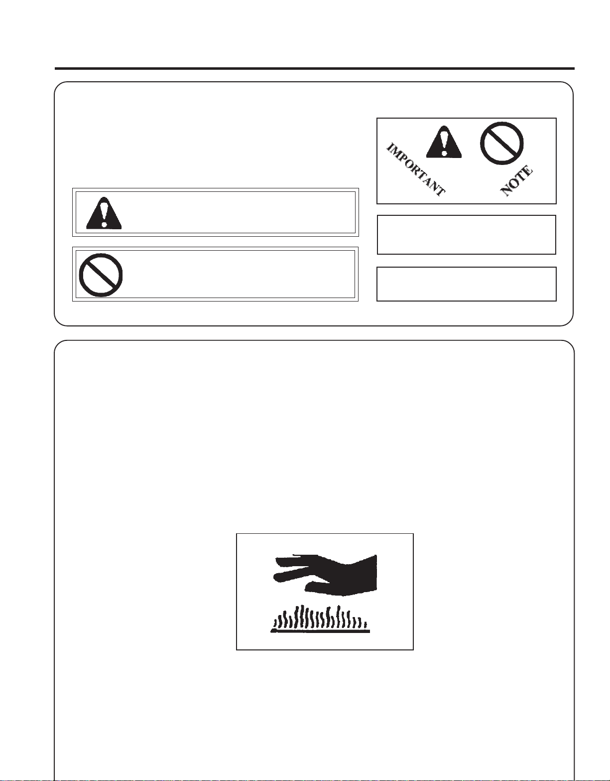
This symbol accompanied by the words WARNING and
DANGER calls attention to an act or condition that can lead to
serious personal injury to operator and bystanders.
The circle with the slash symbol means whatever is shown
within the circle is prohibited.
IMPORTANT The enclosed message
provides information necessary for the
protection of the unit.
NOTE This enclosed message provides tips for
use, care and maintenance of the unit.
3
SAFETY
DECALS
Locate these safety decals on your unit. Make sure the decals are legible and that you understand and follow the
instructions on them. If a decal cannot be read, a new one can be ordered from your ECHO dealer. See PARTS ORDERING instructions for specific information.
Hot Surface Decal
P/N 89016006361
Page 4
4
Shaft Decal
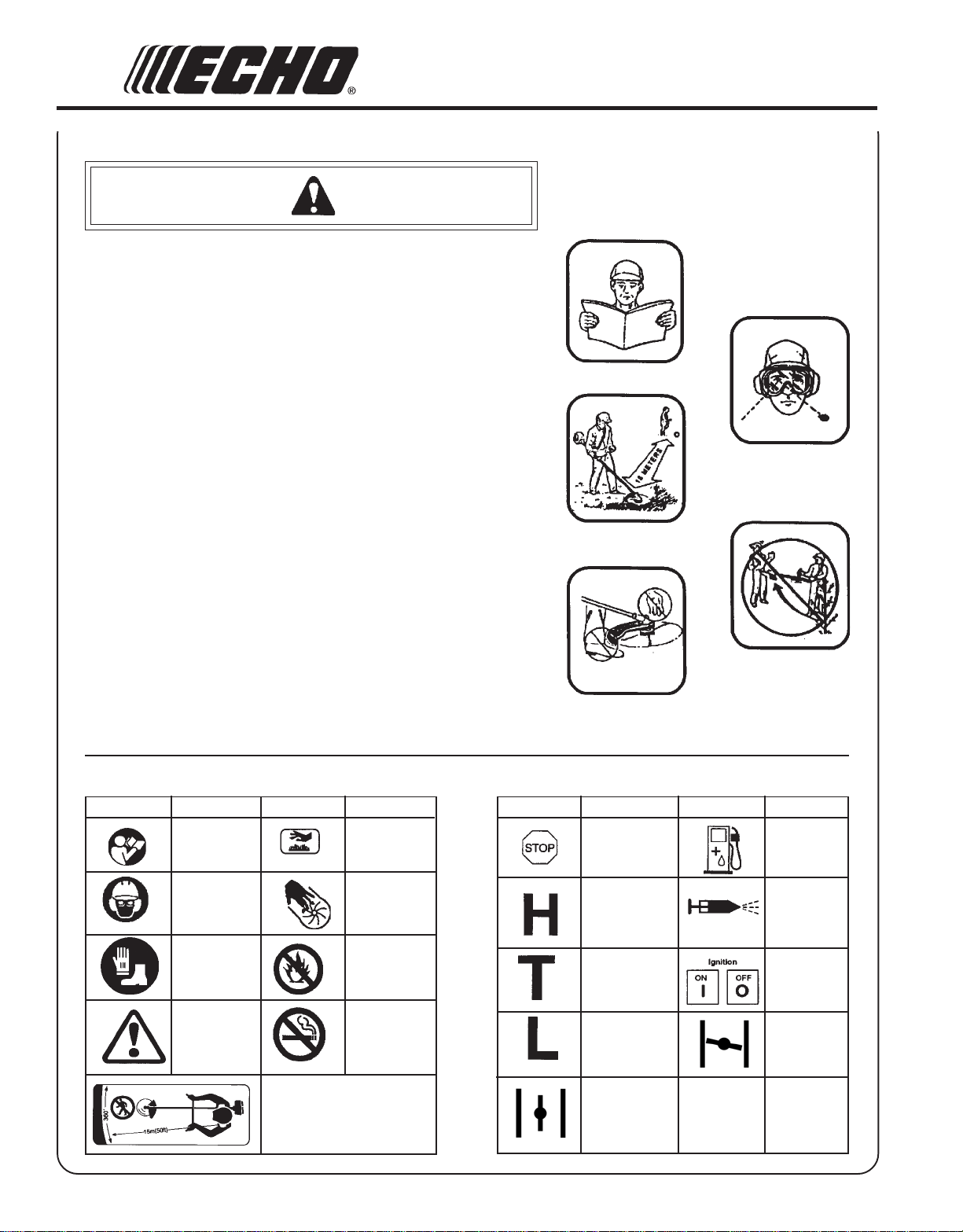
W ARNING DANGER
• This unit can be dangerous and cause serious injury if improperly
used. To reduce injury risk to operator, helpers and bystanders, read
and understand the Operator's and Safety manuals.
• Blindness can occur from objects that are thrown or ricocheted even
with shield in place. Operators, helpers and bystanders must wear
ANSI Z87.1 approved eye protection.
• Always wear hearing protection when operating unit.
• Prevent accidental contact with unit and any cutting attachment.
Maintain a 50 ft. (15M) radius, DANGER ZONE surrounding the
operator. ONLY the operator, dressed in proper protective clothing
should be in the DANGER ZONE.
• Beware of KICKOUT (blade thrust) when using blades. Special
precautions are necessary for blade operation, see your Operator's
and Safety Manuals. ONLY install ECHO approved blades on Brush
Cutters (SRM) models equipped with proper blade shield, U-handles,
harness, blade collar, nut and cotter pin.
• Blade/Cutting attachment does not stop immediately after releasing
throttle. Keep hands and feet clear of blade/cutting attachment unless
engine is shut off and cutting attachment is not moving.
• INSPECT BLADES BEFORE USE.
• DO NOT USE DAMAGED, CRACKED, BENT, DULL OR
IMPROPERLY SHARPENED BLADES.
• Do not remove shields, modify the unit or install attachments or parts
not approved by ECHO. Approved attachment information and
replacement Operator's and Safety Manuals are available from your
ECHO dealer or by writing: ECHO, INCORPORATED,
400 OAKWOOD RD., LAKE ZURICH, IL 60047.
P/N 89016054130
INTERNA TIONAL SYMBOLS
Symbol form/shape
Symbol
description/application
"WARNING, SEE
OPERATOR'S
MANUAL
Wear eyes, ears and
head protection
Wear hand and
foot protection
Safety/Alert
Symbol form/shape
Keep bystanders and helpers
away 15 m (50 ft.).
Symbol
description/application
Hot
Surface
Finger Severing
DO NOT allow
flames or sparks
near fuel.
DO NOT smoke
near fuel.
Symbol form/shape
Symbol
description/application
Emergency stop
Carburetor adjustment
- High speed mixture
Carburetor adjustment
- Idle speed
Carburetor adjustment
- Low speed mixture
Choke Control
"Run"
Position
(Choke Open)
Symbol form/shape
Symbol
description/application
Fuel and oil mixture
Primer Bulb
Ignition
ON/OFF
Choke Control
"Cold Start"
Position
(Choke Closed)
Page 5
SAFETY INSTRUCTIONS
GRASS TRIMMER/BRUSH CUTTER
OPERATOR'S MANUAL
5
PERSONAL
CONDITION AND SAFETY EQUIPMENT
W ARNING DANGER
Trimmer/Brush Cutter users risk injury to themselves and others if the trimmer/brush cutter is used improperly
or safety precautions are not followed. Proper clothing and safety gear must be worn when operating a
trimmer/brush cutter.
Physical Condition
Your judgment and physical dexterity may not be good:
• if you are tired or sick,
• if you are taking medication,
• if you have taken alcohol or drugs.
Operate unit only if you are physically and mentally well.
Eye Protection
Wear eye protection that meets ANSI Z87.1 or CE
requirements whenever you operate the unit.
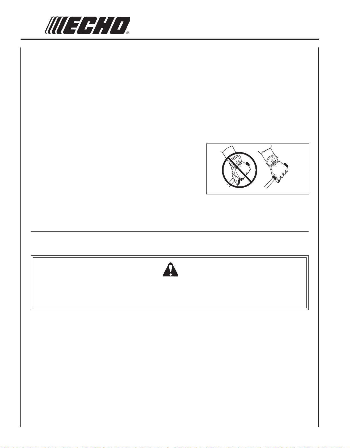
Hand Protection
Wear no-slip, heavy-duty work gloves to improve your
grip on the handle. Gloves also reduce the transmission of
machine vibration to your hands.
Proper Clothing
Wear snug fitting, durable clothing;
• Pants should have long legs, shirts with long sleeves.
• DO NOT WEAR SHORTS,
• DO NOT WEAR TIES, SCARFS, JEWELRY.
Wear protective hair covering to contain long hair.
Wear sturdy work shoes with nonskid soles;
• DO NOT WEAR OPEN TOED SHOES,
• DO NOT OPERATE UNIT BAREFOOTED.
Hot Humid Weather
Heavy protective clothing can increase operator fatigue
which may lead to heat stroke. Schedule heavy work for
early morning or late afternoon hours when temperatures
are cooler.
Hearing Protection
ECHO recommends wearing hearing protection whenever
unit is used.
EXTENDED OPERATION/EXTREME CONDITIONS
Vibration and Cold
It is believed that a condition called Raynaud’s Phenomenon, which
affects the fingers of certain individuals, may be brought about by
exposure to vibration and cold. Exposure to vibration and cold may
cause tingling and burning sensations, followed by loss of color and
numbness in the fingers. The following precautions are strongly
recommended, because the minimum exposure which might trigger the
ailment is unknown.
• Keep your body warm, especially the head, neck, feet, ankles,
hands, and wrists.
• Maintain good blood circulation by performing vigorous arm
exercises during frequent work breaks, and also by not smoking.
• Limit the hours of operation. Try to fill each day with jobs where
operating the trimmer or other hand-held power equipment is not
required.
• If you experience discomfort, redness and swelling of the fingers
followed by whitening and loss of feeling, consult your physician
before further exposing yourself to cold and vibration.
Page 6
6
Repetitive Stress Injuries
It is believed that overusing the muscles and tendons of the fingers,
hands, arms and shoulders may cause soreness, swelling, numbness,
weakness, and extreme pain in those areas. Certain repetitive hand
activities may put you at a high risk for developing a Repetitive Stress
Injury (RSI). An extreme RSI condition is Carpal Tunnel Syndrome
(CTS), which could occur when your wrist swells and squeezes a vital
nerve that runs through the area. Some believe that prolonged exposure
to vibration may contribute to CTS. CTS can cause severe pain for
months or even years.
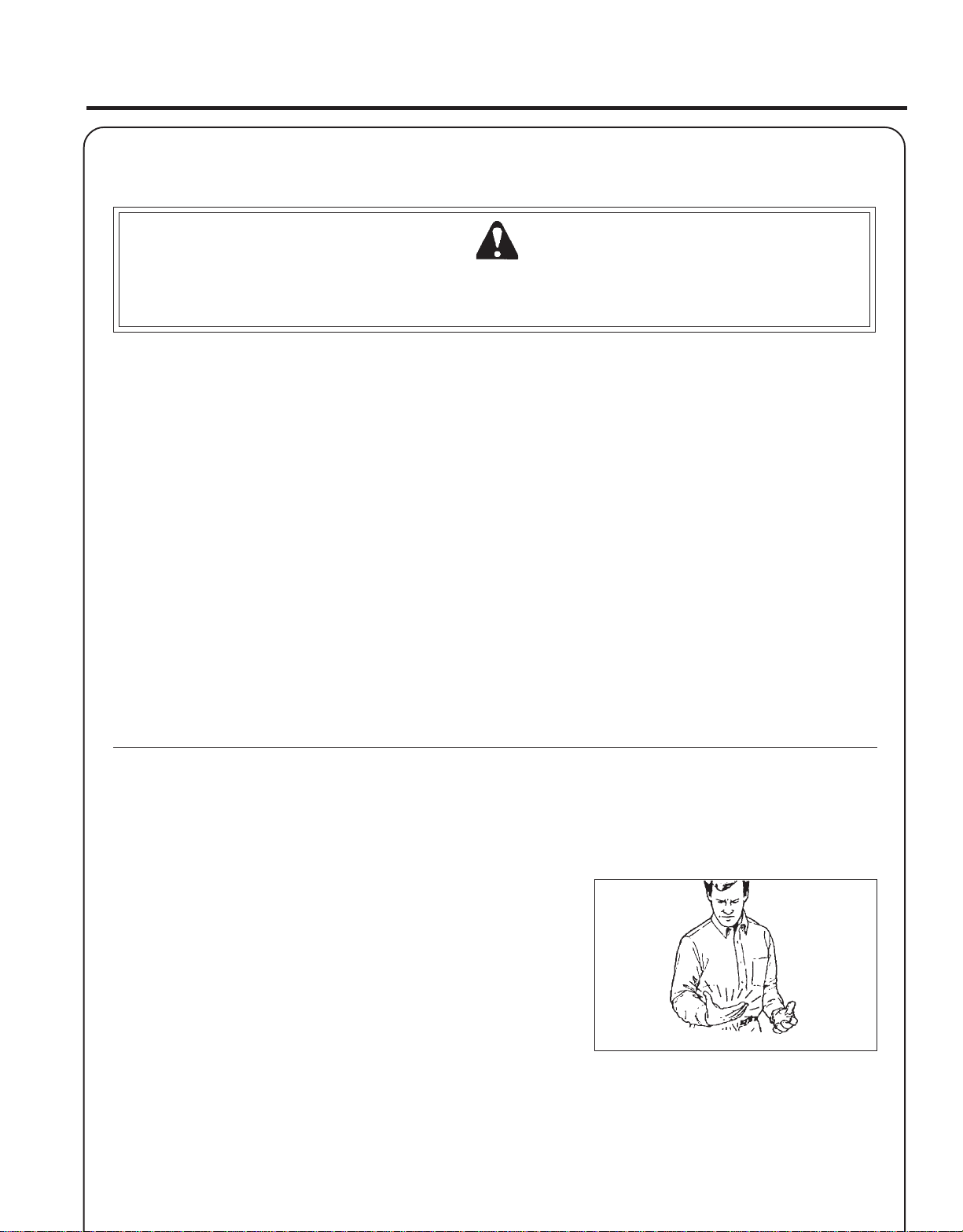
To reduce the risk of RSI/CTS, do the following:
• Avoid using your wrist in a bent, extended, or twisted position.
Instead, try to maintain a straight wrist position. Also, when grasping, use your whole hand, not just the thumb and index finger.
• Take periodic breaks to minimize repetition and rest your hands.
• Reduce the speed and force with which you do the repetitive
movement.
• Do exercises to strengthen the hand and arm muscles.
• Immediately stop using all power equipment and consult a doctor if
you feel tingling, numbness, or pain in the fingers, hands, wrists, or
arms. The sooner RSI/CTS is diagnosed, the more likely permanent
nerve and muscle damage can be prevented.
EQUIPMENT
W ARNING DANGER
Use only ECHO approved attachments. Serious injury may result from the use of a non-approved attachment
combination. ECHO, INC. will not be responsible for the failure of cutting devices, attachments or accessories which
have not been tested and approved by ECHO. Read and comply with all safety instructions listed in this manual and
safety manual.
• Check unit for loose/missing nuts, bolts, and screws. Tighten and/or
replace as needed.
• Inspect fuel lines, tank, and area around carburetor for fuel leaks. DO
NOT operate unit if leaks are found.
• Inspect shield for damage and ensure that the cut-off knife issecurely
in place. Replace if either is damaged or missing.
• Check that the cutting attachment is firmly attached and in safe
operating condition.
• Check that front loop handle and shoulder strap/ or shoulder/
waist harness are adjusted for safe, comfortable operation. See
Assembly Section for proper adjustment.
Page 7
GRASS TRIMMER/BRUSH CUTTER
SAFE OPERATION
W ARNING DANGER
Do not operate this product indoors or in inadequately ventilated
areas. Engine exhaust contains poisonous emissions and can
cause serious injury or death.
Read the Manuals
• Provide all users of this equipment with the Operator’s Manual and
Safety Manual for instructions on Safe Operation.
Clear the Work Area
• Spectators and fellow workers must be warned, and children and
animals prevented from coming nearer than 15 m (50 ft.) while the unit
is in use.
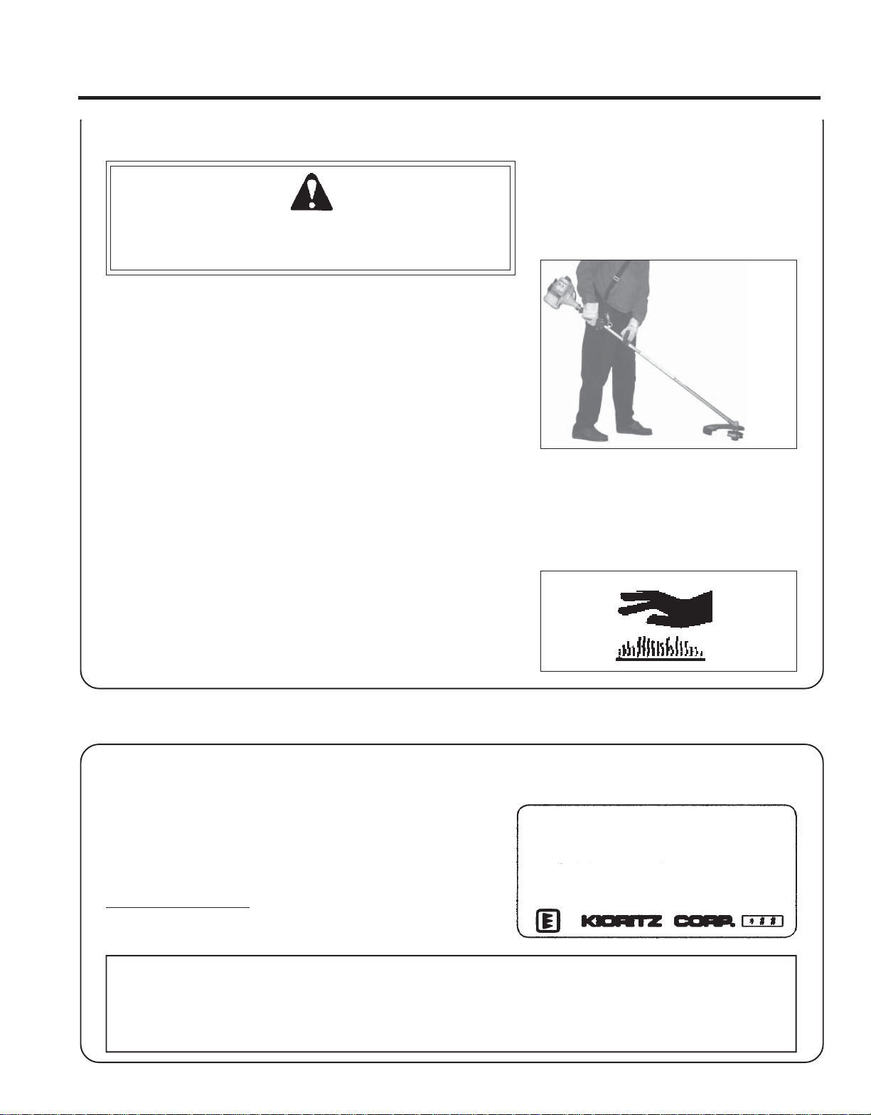
Keep a Firm Grip
• Hold the front and rear handles with both hands, with thumbs and
fingers encircling the handles.
OPERATOR'S MANUAL
7
Keep a Solid Stance
• Maintain footing and balance at all times. Do not stand on slippery,
uneven or unstable surfaces. Do not work in odd positions or on
ladders. Do not over reach.
Avoid Hot Surfaces
• Keep exhaust area clear of flammable debris. Avoid contact during
and immediately after operation.
EMISSION CONTROL
EPA Phase 2
The emission control system for this engine is EM/TWC (Engine
Modification).
Emission Control Label (located on Engine) (EXAMPLE
ONLY, information on label varies by FAMILY).
ENGINE FAMILY: 4EHXS.0214EF DISPLACEMENT: 21.2 CC
IMPORTANT ENGINE INFORMATION
EMISSION COMPLIANCE PERIOD: 300 HOURS
THIS ENGINE MEETS U.S. EPA PH2 EMISSION REGULATIONS FOR SMALL NONROAD ENGINE. REFER TO
OWNER'S MANUAL FOR MAINTENANCE SPECIFICATIONS
AND ADJUSTMENTS.
PRODUCT EMISSION DURABILITY
The 300 hour emission durability compliance period is the time span selected by the manufacturer certifying the
engine emissions output meets applicable emissions regulations, provided that approved maintenance procedures
are followed as listed in the Maintenance Section of this manual.
Page 8
8
DESCRIPTION
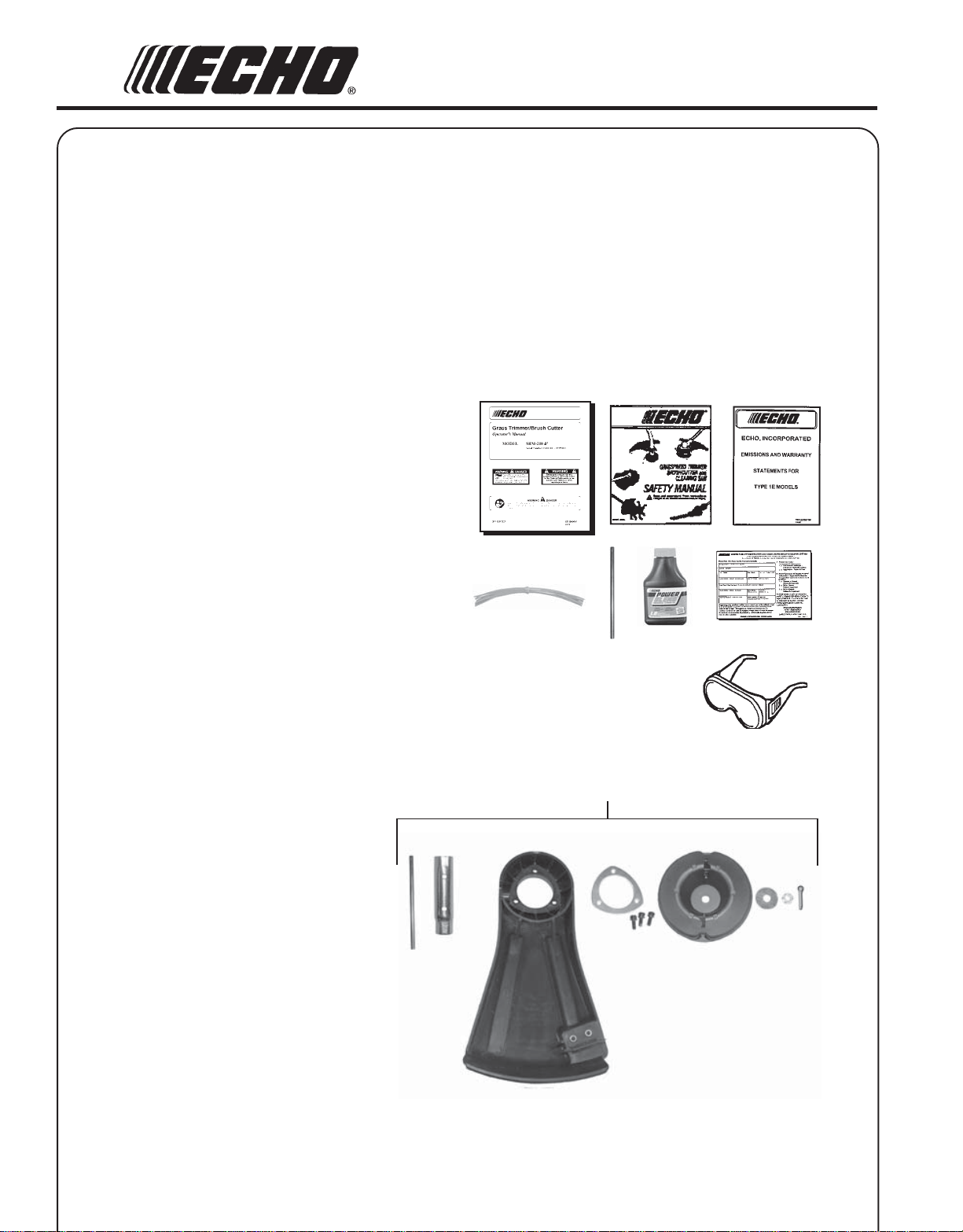
The ECHO product you purchased has been partially assembled for your convenience. Due to packaging restrictions,
installation of the plastic debris shield, nylon line head, and positioning of the front handle are necessary.
After opening the carton, check for damage. Immediately notify your retailer or ECHO Dealer of damaged or missing
parts. Use the contents list to check for missing parts.
* Some units may be factory pre-assembled. No assembly tools are needed and the nylon line head, plastic debris shield,
and mounting hardware, shown in the contents list, are pre-assembled to the unit. Only the front handle may need to be
re-positioned for comfortable operation.
CONTENTS
______1 - Power Head / Drive Shaft Assembly
______1 - Plastic Bag (co-pack)
______ - 1, Operator's Manual
______ - 1, Safety Manual
______ - 1, Warranty Registration Card
______ - 1, Limited Warranty Statement
______ - 1, Locking Tool, P/N 89751801131
______ - 1, Safety Glasses
______ - 1, Echo Power Blend TM 2-stroke oil sample
* ___ - 1, Nylon Trimmer Head
* ___ - 1, wrench 17x14.5, P/N X602000030
* ___ - 2, locking tool, P/N 89751801131
* ___ --1, Plastic shield
* ___ --1, shield plate
* ___ --3, 5mm x 16mm screws (shield mtg.)
* _____ - 1, Large Washer
* _____ - 1, Split Pin
* _____ - 1, Nut, L.H. M10 x 1.25
______ - 12, 8 in. x .095 Pre-Cut Nylon Line
*
Page 9
GRASS TRIMMER/BRUSH CUTTER
OPERATOR'S MANUAL
12
11
9
20
Safety
Video
7
6
8
9
18
19
5
17
13
16
15
4
3
2
14
1
10
Page 10

10
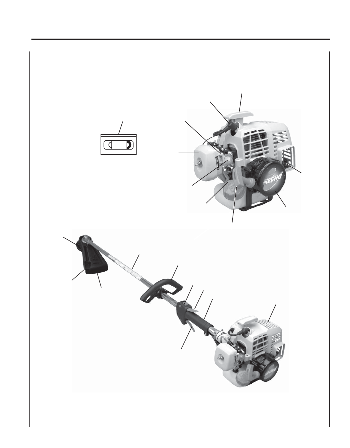
1. POWER HEAD - Includes the Engine, Clutch, Fuel System, Ignition System and Recoil Starter.
2. GRIP - Rear (right hand) handle.
3. THROTTLE TRIGGER LOCKOUT - This lever must be held during starting. Operation of the throttle trigger is
prevented unless throttle trigger lockout lever is engaged.
4. STOP SWITCH - "SLIDE SWITCH" mounted on top of the Throttle Trigger Housing. Move switch FORWARD to
RUN, BACK to STOP.
5. FRONT HANDLE - The Front (loop) handle is loosely assembled to the Drive Shaft assembly and must be positioned
for proper cutting attitude and operator comfort.
6. DRIVE SHAFT ASSEMBLY - Includes the Gear Housing assembly, flex drive cable and Safety Decal.
7. NYLON CUTTER HEAD - Contains replaceable nylon trimming lines.
8. CUT-OFF KNIFE - Trims line to the correct length (5 in.). If trimmer is operated without a cut-off knife the line may be
too long - more than (5 in.) - the operating speed will slow, the engine overheat and performance will suffer.
9. PLASTIC DEBRIS SHIELD ASSEMBLY - Included in plastic bag (co-pack). MUST be installed on unit before use,
see Assembly Instructions. Shield assembly includes the Cut-Off Knife. Mounts on the Gear Housing Assembly just
above the cutting attachment. Helps protect the operator by deflecting debris produced during the trimming operation.
This shield must be replaced with the steel shield for blade use.
10. THROTTLE TRIGGER - Spring loaded to return to idle when released. During acceleration, press trigger gradually for
best operating technique.
11. SPARK PLUG - Provides spark to ignite fuel mixture.
12. TOP GUARD - Protects arm from the hot engine.
13. SPARK ARRESTOR - CATALYTIC MUFFLER / MUFFLER -The muffler or catalytic muffler controls exhaust noise
and emission. The spark arrestor screen prevents hot, glowing particles of carbon from leaving the muffler. Keep
exhaust area clear of flammable debris.
14. FUEL TANK - Contains fuel and fuel filter.
15. RECOIL STARTER HANDLE/ROPE - Pull recoil starter handle/rope using light pulling force, approximately 2/3
(2 ft.) of rope length. Two (2) to Six (6) pulls are required to properly tension starter spring prior to automatic engine
engagement. DO NOT let handle snap back or damage to unit will occur.
16. FUEL TANK CAP - Covers and seals fuel tank opening.
17. PRIMER BULB - Pumping primer bulb before starting engine draws fresh fuel from the fuel tank priming the carburetor
for starting. Pump primer bulb until fuel is visible and flows freely in the clear fuel tank return line. Pump bulb an
additional 4 or 5 times.
18. AIR CLEANER - Contains replaceable filter element.
19. CHOKE - The choke control is located on the top of the air filter case. Move choke lever to "Cold Start" to close
choke for cold start. Move choke lever to "Run" position to open choke.
20. SAFETY VIDEO - (Not included with unit) P/N 99922202540 English version only is available at a cost of $5.00 from
ECHO, INC. or any authorized ECHO dealer. The video overviews safety precautions and proper operating techniques
and is supplemental to the Safety Manual. Read and understand the Safety Manual for complete information on safe
operation.
Page 11

GRASS TRIMMER/BRUSH CUTTER
OPERATOR'S MANUAL
SPECIFICATIONS
MODEL -----------------------------------------------------SRM-210
Length-------------------------------------------------------1778 mm (70.0 in.)
Width-------------------------------------------------------- 250 mm (9.84 in.)
Height ------------------------------------------------------- 325 mm (12.8 in.)
Weight (dry) w/cutter head------------------------------- 5.4 kg (11.9 lb.)
Engine Type ------------------------------------------------ Air cooled, two-stroke, single cylinder gasoline engine
Bore----------------------------------------------------------32.2 mm (1.27 in.)
Stroke--------------------------------------------------------26.0 mm (1.02 in.)
Displacement -----------------------------------------------21.2 cc (1.29 cu. in.)
Exhaust ------------------------------------------------------ Spark Arrestor Muffler
Carburetor --------------------------------------------------Zama model w/purge pump
Ignition System --------------------------------------------Flywheel magneto, capacitor discharge ignition type
Spark Plug --------------------------------------------------NGK BPMR-8Y Gap 0.65 mm (0.026 in.)
Fuel ----------------------------------------------------------Mixed (Gasoline and Two-stroke Oil)
Fuel/Oil Ratio -----------------------------------------------50:1 two-stroke air cooled engine oil
Gasoline ----------------------------------------------------- 89 Octane unleaded. DO NOT use fuel containing methyl alcohol,
more than 10% ethyl alcohol or 15% MTBE.
Oil ------------------------------------------------------------ Power Blend TM Premium Universal 2-Stroke Oil
Fuel Tank Capacity ----------------------------------------0.45 lit. (15.2 US fl. oz.)
Recoil Starter System --------------------------------------Automatic Recoil Starter
Clutch -------------------------------------------------------Centrifugal Type
Drive Shaft -------------------------------------------------- 1/4 in. Flex Shaft
Rotating Direction ----------------------------------------- Counter-Clockwise viewed from top
Cutter Head -------------------------------------------------Nylon line head (2-line) with .095 line capacity 203mm (8 in.)
Handle------------------------------------------------------- Front - Loop and Right Rear Handle w/rubber grips
Shoulder Harness ------------------------------------------ Optional
Idle Speed RPM -------------------------------------------- 2,400 - 3,200
Wide Open Throttle Speed (W.O.T.) RPM ------------- 8,000 - 10,000
11
IMPORTANT
This spark ignition system complies with Canadian ICES-002.
Page 12

12
ASSEMBLY
W ARNING DANGER
Use only ECHO approved attachments for these models. Serious injury may result from the use of non-approved
attachment combinations. Read and comply with all safety instructions listed in this manual and attachment manual.
ECHO, INC. will not be responsible for the failure of cutting devices, attachments or accessories which have not been
tested and approved by ECHO for use with these units.
Tools Required: Screwdriver, Head Locking Tool (2), 17x14.5mm
Wrench, Needle Nose Pliers
Parts Required: Plastic Shield, Shield Plate, three (3) 5mm x 16mm
screws, Nylon Line Head, Two (2) Pre-cut Nylon Line
8 in. x .095 in., large washer, split pin, hex nut L.H. M10 x 1.25
PLASTIC SHIELD INSTALLATION
(For Nylon Line Operation)
NOTE
The plastic shield is for use with the Nylon Line Head only.
Install Metal Shield when using plastic or metal blades.
1 . Remove plastic sleeve and upper plate (A) from PTO shaft.
2. Install the shield on the bottom of the bearing housing flange.
3 . Place shield plate (B) on shield, align holes and install three (3)
5x16 mm screws.
4 . Install upper plate (A) onto PTO shaft.
B
A
Page 13

GRASS TRIMMER/BRUSH CUTTER
NYLON LINE HEAD INSTALLATION
1. Align hole in upper plate with notch in edge of gear housing and
insert head locking tool (C).
2 . Be sure upper plate (A) remains on PTO shaft.
3 . Place line head onto PTO shaft. Followed by large metal washer.
4 . Thread L.H. nut on PTO shaft. Tighten securely.
5 . Install new split pin.
6 . Remove locking tool (C).
NYLON LINE INSTALLATION
1. Shut engine off. Lay unit on the ground with head assembly up.
OPERATOR'S MANUAL
C
A
13
2. Remove old nylon line through center recess of head.
3. Thread new lines through outside holes (D) in housing until ends
meet in center of recess.
NOTE
Insert cutting line ends to center of head recess to insure easy
removal of used lines.
FRONT HANDLE INSTALLATION
1 . Position front handle for comfortable operation and secure screws.
D
D
Page 14

14
PRE - OPERATION
OPERATION
WITH BLADES
Preparing the Trimmer/Brush Cutter for Blade Use
W ARNING DANGER
Blade use DEMANDS specific Brush Cutter configuration. Operation without specified shield, harness, and handle
can result in serious personal injury.
Grass/Weed Blades Require:
Install Blade Conversion Kit, P/N 99944200415 Includes metal shield (A), barrier bar (B), and
shoulder harness (C).
A
B
C
NOTE
The Barrier Bar is used to restrict rearward movement of the unit. The Barrier Bar is NOT A HANDLE and should not
be gripped when using or carrying the unit.
Brush/Clearing Blades Require:
D
Install U-Handle / Blade Conversion Kit, P/N
99944200521 - Includes metal shield (A), shoulder
harness with hip pad (C), and U-Handles (D).
A
C
Choosing the Correct Blade
W ARNING DANGER
The type of Blade used MUST be matched to the type and size of material cut. An improper or dull blade can
cause serious personal injury. Blades MUST be sharp. Dull blades increase the chance of kick out and injury
to yourself and bystanders.
Page 15
GRASS TRIMMER/BRUSH CUTTER
Plastic/Nylon Blades may be used where ever the nylon line head
is used. DO NOT use this blade for heavy weeds or brush!
8 Tooth Weed/Grass Blade P/N 69600120331 is designed for grass,
garden debris and thick weeds. DO NOT use this blade for brush or
heavy woody growth, 19 mm (3/4 in.) diameter or larger.
80 Tooth Brush Blade (P/N 69500120331) is designed for cutting brush
and woody growth up to 64 mm (2-1/2 in.) diameter.
OPERATOR'S MANUAL
15
22 Tooth Clearing Blade (99944200130) is designed for dense thickets
and saplings up to 64 mm (2-1/2 in.) diameter.
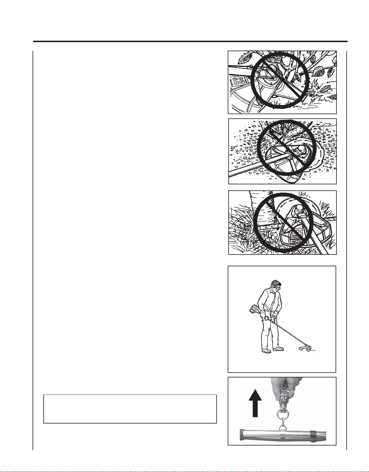
Use Shoulder/Waist Harness (P/N 99944200200) Use of the Shoulder/
Waist Harness is recommended for ALL Trimmer/Brush Cutter use. The
Shoulder/Waist Harness suspends the trimmer from the operator's
shoulder and reduces operator fatigue.
The restrictive harness enhances operator safety by reducing the
possibility of blade contact with the operator's hands and feet.
NOTE
In case of Emergency, pull up on the Quick Release Collar to
disconnect the trimmer from the harness.
Page 16

16
FUEL
Fuel Requirements
Gasoline - Use 89 Octane [R+M/2] (mid grade or higher) gasoline or
gasohol known to be good quality. Gasohol may contain up to 10%
Ethyl (grain) alcohol or 15% MTBE (methyl tertiary-butyl ether).
Gasohol containing methyl (wood) alcohol is NOT approved.
Two Stroke Oil - A two-stroke engine oil meeting ISO-L-EGD (ISO/CD
13738) and J.A.S.O. FC Standards must be used. Echo brand premium
Power Blend TM Universal 2-Stroke Oil meets these standards. Engine
problems due to inadequate lubrication caused by failure to use an ISOL-EGD and J.A.S.O. FC certified oil, such as Echo premium Power Blend
TM
, will void the two-stroke engine warranty. (Emission related parts
only are covered for two years, regardless of two-stroke oil used, per
the statement listed in the Emission Defect Warranty Explanation.)
IMPORTANT
Echo premium Power Blend TM Universal 2-Stroke Oil may be mixed
at 50:1 ratio for application in all Echo engines sold in the past
regardless of ratio specified in those manuals.
Mixing Instructions
1 . Fill an approved fuel container with half of the required amount of
gasoline.
2 . Add the proper amount of 2-stroke oil to gasoline.
3 . Close container and shake to mix oil with gasoline.
4 . Add remaining gasoline and remix.
5 . Install fuel container cap and wipe any spilled fuel from container
and surrounding area.
IMPORTANT
Spilled fuel is a leading cause of
hydrocarbon emissions. Some states
may require the use of automatic fuel
shut-off containers to reduce fuel
spillage. Contact your ECHO dealer for
ordering information.
After refueling
• Wipe any spilled fuel from the unit.
• Move at least 3 m (10 ft.) from refueling
location before starting the engine.
After use
• DO NOT store a unit with fuel in its tank.
Leaks can occur. Return unused fuel to an
approved fuel storage container.
Storage
Fuel storage laws vary by locality. Contact
your local government for the laws affecting
your area. As a precaution, store fuel in an
approved, air tight container. Store in a well
ventilated, unoccupied building, away from
sparks and flames. Do not store fuel longer
than 30 days.
IMPORTANT
Stored fuel ages. Do not mix more fuel
than you expect to use in thirty (30)
days, ninety (90) days when a fuel
stabilizer is added.
Handling Fuel
W ARNING DANGER
Fuel is VERY flammable. Use extreme care when mixing, storing or
handling, or serious personal injury may result.
• Use an approved fuel container.
• DO NOT smoke near fuel.
• DO NOT allow flames or sparks near fuel.
• Fuel tanks/cans may be under pressure. Always loosen fuel caps
slowly allowing pressure to equalize.
• NEVER refuel a unit when the engine is HOT!
• NEVER refuel a unit with the engine running.
• DO NOT fill fuel tanks indoors. ALWAYS fill fuel tanks outdoors
over bare ground.
• Securely tighten fuel cap after refueling.
• Inspect for fuel leakage. If fuel leakage is found, do not start or
operate unit until leakage is repaired.
IMPORTANT
Stored two-stroke fuel may separate.
ALWAYS shake fuel container thoroughly before each use.
Page 17

OPERATION
GRASS TRIMMER/BRUSH CUTTER
OPERATOR'S MANUAL
17
STARTING
COLD ENGINE
W ARNING DANGER
The attachment will operate immediately when the engine starts and
could result in loss of control and possible serious injury. Keep
movable parts of the attachment off the ground and away from
objects that could become entangled or thrown.
1. Stop Switch
Move stop switch button (A) forward away from the STOP position.
2. Choke
Move choke lever (B) to Cold Start Position ( ).
3. Primer
Pump primer bulb (C) until fuel is visible and flows freely in the clear
fuel tank return line. Pump bulb an additional 4 or 5 times.
NOTE
Energy is stored in the starter spring each time the handle/rope is
pulled. Generally two to six pulls, using light pulling forces, will
store enough energy to engage the starter and spin the engine. Do
not pull the rope out to end stop.
A
B
4. Recoil Starter
Lay the unit on a flat, clear area. Firmly grasp right hand grip and
throttle trigger lockout with left hand, and fully depress throttle
trigger to wide open position. Gently pull starter handle/rope (D)
until engine fires or 2 to 3 engine engagements.
5. Choke
After engine fires or 2 to 3 engine engagements, move choke lever
(B) to Run position ( ). Hold throttle trigger and throttle trigger
lockout fully depressed, and pull starter handle/rope until engine
starts and runs. Release throttle trigger and allow unit to warm up at
idle for several minutes.
NOTE
If engine does not start with choke in “Run” position after 5 engine
engagements, repeat instructions.
6 . After engine warm up, gradually depress throttle trigger to increase
engine RPM to operating speed.
C
D
Page 18

18
STARTING WARM ENGINE
The starting procedure is the same as Cold Start except DO NOT close
the choke, and do not depress throttle trigger to wide open position.
W ARNING DANGER
The attachment should not move at idle, otherwise serious personal
injury may result.
NOTE
If attachment moves, readjust carburetor according to “Carburetor
Adjustment” instructions in this manual or see your ECHO Dealer.
1. Stop Switch
Move stop switch button (A) forward away from the STOP position.
A
2. Primer
Pump primer bulb (C) until fuel is visible and flows freely in the clear
fuel tank return line. Pump bulb an additional 4 or 5 times.
3. Recoil Starter
Lay the unit on a flat, clear area and pull the recoil starter handle (D)
until the engine fires.
NOTE
If engine does not start after 5 engine engagements, use Cold Start
Procedure.
C
D
Page 19

STOPPING ENGINE
GRASS TRIMMER/BRUSH CUTTER
OPERATOR'S MANUAL
19
1. Throttle
Release throttle and allow engine to return to idle before shutting off
engine.
2. Stop Switch
Move stop switch button (A) backward to STOP position.
W ARNING DANGER
If engine does not stop when stop switch is moved to STOP
position, close choke - COLD START position - to stall engine.
Have your ECHO dealer repair stop switch before using trimmer
again.
A
MAINTENANCE
Your ECHO trimmer is designed to provide many hours of trouble free service. Regular scheduled maintenance will help
your trimmer achieve that goal. If you are unsure or are not equipped with the necessary tools, you may want to take
your unit to an ECHO Service Dealer for maintenance. To help you decide whether you want to DO-IT-YOURSELF or
have the ECHO Dealer do it, each maintenance task has been graded. If the task is not listed, see you Echo Dealer for
repairs.
SKILL LEVELS
Level 1 = Easy to do. Most required tools come with unit.
Level 2 = Moderate difficulty. Some specialized tools may be required.
Level 3 = Experience required. Specialized tools are required. ECHO recommends that
the unit be returned to your ECHO dealer for servicing.
ECHO offers REPOWERTM Maintenance Kits and Parts to make your maintenance job easier. Below each task heading
are listed the various part numbers required for that task. See your ECHO dealer for these parts.
Page 20

20
MAINTENANCE INTERV ALS
/TNENOPMOC
METSYS
ECNANETNIAM
ERUDECORP
D'QER
LLIKS
LEVEL
ROYLIAD
EROFEB
ESU
YREVE
LEUFER
3
SHTNOM
09RO
SRUOH
6
SHTNOM
072RO
SRUOH
YLRAEY
006
SRUOH
serudecorPecnanetniaMrelaeDohcEdednemmoceR
troPtsuahxErednilyCnobraceD/naelC/tcepsnI 3 C/I
etniaMflesruoY-tI-oD
serudecorPecnan
retliFriAecalpeR/naelC/tcepsnI 1 C/I*R
ekohCnaelC/tcepsnI 2 C/I
retliFleuFecalpeR/tcepsnI 1 I*
R/I
skael,metsySleuFecalpeR/tcepsnI 1 *III
metsySgnilooCnaelC/tcepsnI 2 C/I
rotserrAkrapSrelffuMecalpeR/tcepsnI 2 *
xelF(tfahSevirD
esaerG 2 )1(I
R/I
)sledoMelbaC
gnisuoHraeGesaerG 2 )2(I
epoRretratSlioceRnaelC/tcepsnI 1 *C/I
gulPk
rapSnaelC/tcepsnI 2 C/I*R
stloB/stuN/swercSecalpeR/nethgiT/tcepsnI 1 *R/I
* ..noitcepsnignirudraewroegamadfognidnifehtnodesaberaecalperotsnoitadnemmocerllA
)1( OHCEylppA
)2( OHCEylppA
-ETONTNATROPMI deriuqerfoycneuqerfehtenimretedlliwecneirepxeruoydnaesulaut
.ecnanetniam
MT
EBUL
®
MT
EBUL
®
:SETONERUDECORPECNANETNIAM
SEDOCRETTELERUDECORPECNANETNIAM NAELC=C,ECALPER=R,TCEPSNI=I:
.esufosruoh52yreve
.esufosruoh05yreve
cA.mumixameranwohsslavretniemiT
Page 21

GRASS TRIMMER/BRUSH CUTTER
AIR FILTER
Level 1.
Tools required: 25 - 50 mm (1 - 2 in.) Cleaning Brush
Parts required: 90008 REPOWERTM AIR & FUEL FILTER KIT.
1 . Close choke (Cold Start Position [ ]). This prevents dirt from
entering the carburetor throat when the air filter is removed.
Brush accumulated dirt from the air cleaner area.
2 . Remove the air cleaner cover. Clean and inspect the element for
damage. If element is fuel soaked and very dirty, replace.
OPERATOR'S MANUAL
21
3 . If element can be cleaned and reused, be certain it:
•still fits the cavity in the air cleaner cover.
•is installed with the original side out.
NOTE
Carburetor adjustment may be needed after air filter cleaning/
replacement.
FUEL FILTER
Level 1.
Tools required: 200 - 250 mm (8 - 10 in.) length of wire with one end
bent into a hook, Clean rag, funnel, and an approved
fuel container
Parts required: 90008 REPOWERTM AIR & FUEL FILTER KIT.
W ARNING DANGER
Fuel is VERY flammable. Use extreme care when mixing, storing or
handling, or serious personal injury may result.
1. Use a clean rag to remove loose dirt from around fuel cap and
empty fuel tank.
2. Use the “fuel line hook” to pull the fuel line and filter from the
tank.
3 . Remove the filter from the line and install the new filter.
Page 22

22
SPARK PLUG
Level 2.
Tools required: T-Wrench, feeler gauge, soft metal brush
Parts Required: REPOWERTM Tune-Up Kit P/N 90074C
1 . Remove spark plug and check for fouling, worn and rounded
center electrode.
2 . Clean the plug or replace with a new one. DO NOT sand blast to
clean. Remaining sand will damage engine.
3. Adjust spark plug gap by bending outer electrode.
4 . Tighten spark plug to 145 - 155 kg/cm (125 - 135 in. lb.).
0.65 mm
(0.026 in.)
COOLING SYSTEMS CLEANING
Level 2.
Tools required: Cross-head screwdriver, 3 and 4 mm hex wrench,
25 - 50mm (1 - 2 in.) cleaning brush
Parts Required: None if you are careful.
IMPORTANT
To maintain proper engine operating temperatures, cooling air
must pass freely through the cylinder fin area. This flow of air
carries combustion heat away from the engine.
Overheating and engine seizure can occur when:
• Air intakes are blocked, preventing cooling air from reaching the
cylinder.
• Dust and grass build up on the outside of the cylinder. This build up
insulates the engine and prevents the heat from leaving.
Removal of cooling passage blockages or cleaning of cooling fins is
considered “Normal Maintenance”. Any failure attributed to lack of
maintenance is not warranted.
Page 23

GRASS TRIMMER/BRUSH CUTTER
1 . Disconnect spark plug lead from spark plug.
2 . Release stored energy in power spring by removing spark plug.
3 . Remove three (3) screws (A) from starter assembly and remove
starter.
NOTE
DO NOT disassemble the starter assembly.
OPERATOR'S MANUAL
23
4 . Remove the four screws that retain the engine cover. Two at the
inside top of the mounting plate (B), one on the top guard (C), and
one at the muffler cover (D).
5 . Disengage the heat deflector tabs (E) under the muffler from the
slots in the engine/muffler cover.
6 . Lift the cover from the engine.
D
B
A
C
D
E
7. Reinstall spark plug and starter assembly to prevent dirt and debris
from entering engine and starter.
NOTE
When installing starter housing to mounting body, be sure that
drive starter cam engages the starter pawls correctly.
Page 24

24
8 . Use a brush to remove dirt from the cylinder fins.
IMPORTANT
DO NOT use a metal scraper to remove dirt from the cylinder fins.
9 . Remove grass and leaves from the grid between the starter and fuel
tank.
10. Reassemble parts in reverse order of removal. When installing the
cover, be certain:
• the tabs of the deflector shield (E) are in the slots of the cover
• the fuel check valve (F) is positioned in the cover
• the spark plug is tightened securely
• the ignition wire (G) is not pinched
E
G
F
Page 25
GRASS TRIMMER/BRUSH CUTTER
EXHAUST SYSTEM
Spark Arrestor Screen
Level 2.
Tools required: Cross-head screwdriver, soft metal brush.
Parts Required: Screen, Gasket
1 . Remove engine cover. See “Cleaning Cooling System” pages
22 - 24 for instructions.
OPERATOR'S MANUAL
25
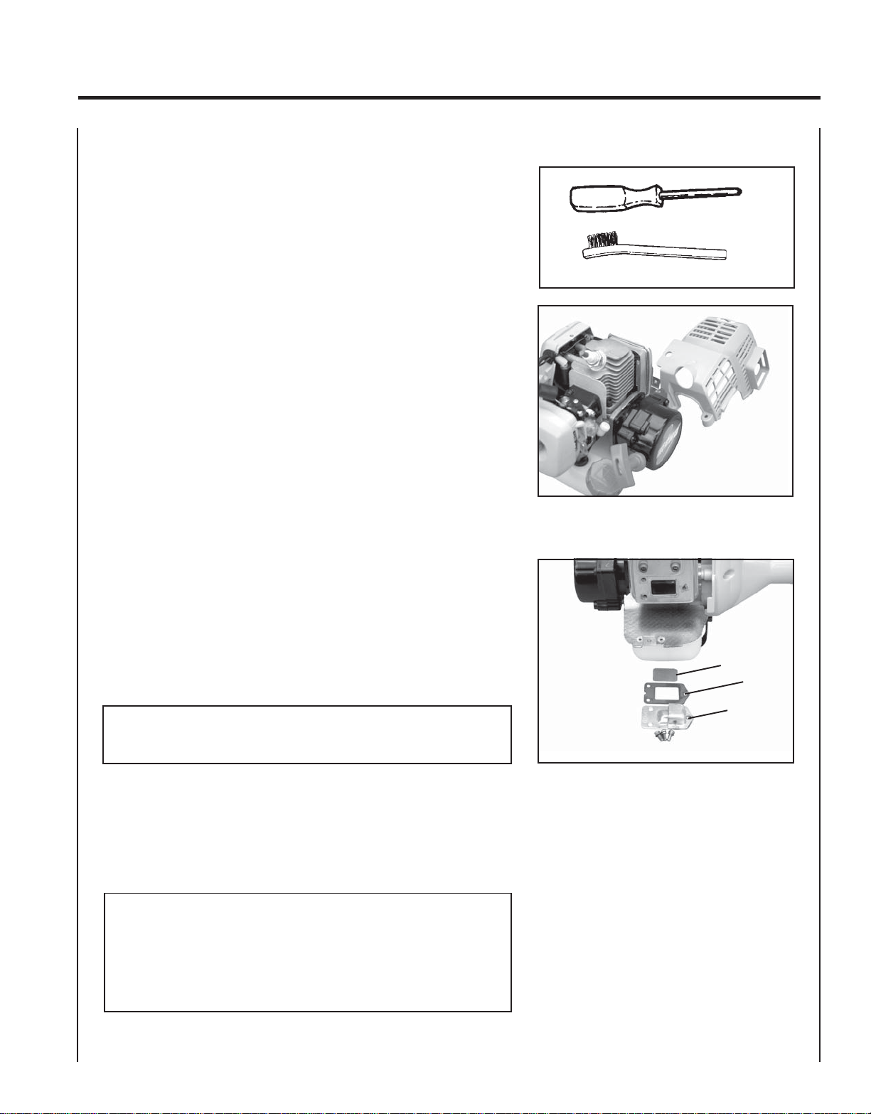
2 . Remove spark arrestor screen cover (A), gasket (B), and screen (C)
from muffler body.
3 . Clean carbon deposits from muffler components.
4 . Replace screen if it is cracked, plugged or has holes burned through.
5 . Reassemble in reverse order of removal. Make sure screen is
positioned properly before tightening screws.
NOTE
When installing the engine cover, be certain the tabs of the metal
deflector shield are in the slot of the engine cover.
Cylinder Exhaust Port
Level 3
IMPORTANT
The cylinder exhaust port must be inspected and cleaned of excess
carbon every 3 months or 90 hours of operation in order to maintain
this engine within the emissions durability period. ECHO strongly
recommends that you return your unit to your ECHO dealer for this
important maintenance service.
C
B
A
Page 26
26
CARBURETOR ADJUSTMENT
Engine Break-In
New engines must be operated for a minimum of two tanks of fuel
before carburetor adjustments can be made. During the break-in period,
your engine performance will increase and exhaust emissions will
stabilize. Idle speed can be adjusted as required.
High Altitude Adjustment
High altitude adjustment is not required for proper operation of this
engine.
Idle Speed Adjustment
Idle speed adjustment may be required periodically to comply with
specifications for this unit. See "Specifications," for correct idle speed.
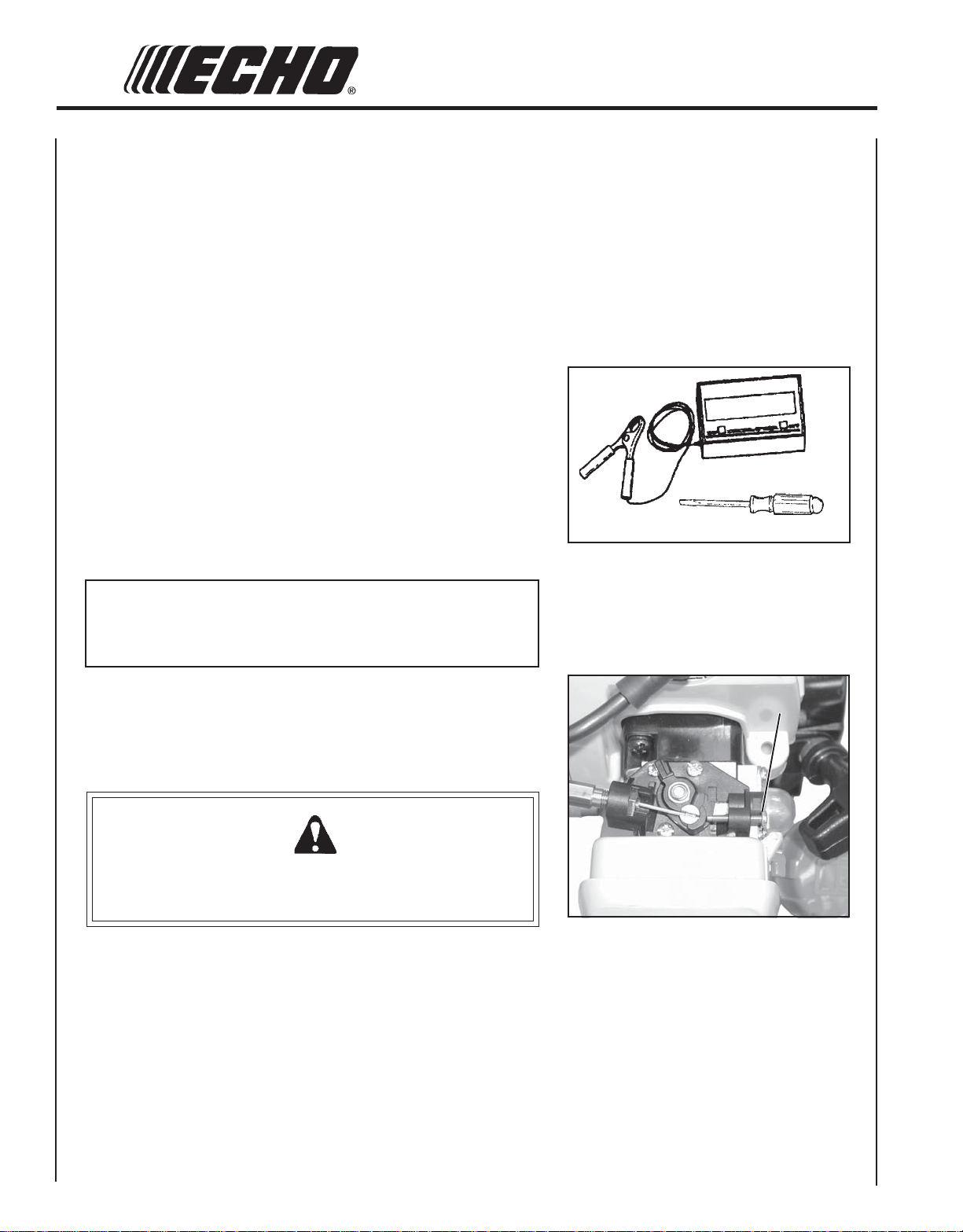
Level 2.
Tools required: Screwdriver, Tachometer (ECHO P/N 99051130017).
NOTE
Every unit is run at the factory and the carburetor is set in compliance with emission regulations. This carburetor does not have
acceleration and high speed adjustment needles.
1. Check idle speed using a tachometer, and reset if necessary. Turn
idle screw (A) clockwise to increase idle speed; counter clockwise to
decrease idle speed.
W ARNING DANGER
When carburetor adjustment is completed, cutting attachment
should not move at idle, otherwise serious personal injury may
result.
A
Page 27

GRASS TRIMMER/BRUSH CUTTER
LUBRICA TION
Level 1.
Tools required: 8 & 13 mm Open End Wrench, Cross Head
Screwdriver, Clean rag, Grease gun P/N 91016
Parts Required: ECHO® LUBETM 8 oz. (P/N 91014) or Lithium Base
Grease.
OPERATOR'S MANUAL
27
Gear Housing
1 . Clean all loose debris from gear box.
2 . Remove plug (A) and check level of grease.
3 . Add grease if necessary, DO NOT over fill.
Drive Shaft
1 . Loosen two (2) screws (B) and remove center locating screw (C).
Pull gear box and shield from drive shaft housing.
2 . Pull flexible cable from the drive shaft housing, wipe clean and
recoat with a thin coating [15 ml (1/2 oz.)] of grease.
3 . Slide the flexible cable back in the drive housing. DO NOT get
dirt on the flex cable.
A
A
D
B
C
A
4. Install the gear housing and shield assembly.
IMPORTANT
Flat edge of washers (D) must be against drive shaft.
Page 28

28
SHARPENING MET AL BLADES
Three styles of metal blades are approved for use on the ECHO Brush
Cutter. The 8-tooth blade can be sharpened during normal maintenance.
The clearing blade and 80 tooth blade require professional service.
Before sharpening, CLOSELY inspect blade for cracks (look at the
bottom of each tooth and the center mounting hole closely), missing
teeth and bending. If ANY of these problems are discovered, replace
the blade.
When sharpening a blade, always remove the same amount of materials
from each tooth to maintain balance. A blade that is not balanced will
cause unsafe handling due to vibration and can result in blade failure.
Tool required: Flat file (preferred). Electric grinder if special care is
used. Round (rat tail) file for gullet (radius).
1 . File each tooth at a 30 degree angle a specific number of times,
eg. 4 strokes per tooth. Work your way around the blade until
all teeth are sharp.
2 . DO NOT file the 'gullet' (radius) of the tooth with the flat file.
The radius must remain. A sharp corner will lead to a crack and
blade failure.
IMPORTANT
If an electric grinder is used, use care not to overheat teeth, do not
allow tips/tooth to glow red or turn blue. DO NOT place blade in
cooling water. This will change the temper of the blade and could
result in blade failure.
3. After sharpening teeth, check each tooth radius for evidence of a
square (sharp) corner. Use the round (rat tail) file to renew the
radius.
Page 29

TROUBLESHOOTING
melborPkcehCsutatSesuaCydemeR
GRASS TRIMMER/BRUSH CUTTER
OPERATOR'S MANUAL
TRAHCGNITOOHSELBUORTMELBORPENIGNE
29
roterubractaleuFroterubractaleufoNdeggolcreniartsleuF
deggolcenilleuF
roterubraC
rednilyctaleuFrednilyctaleufoNroterubraCrelaedohcEruoyeeS
leufhtiwtewrelffuMhcirooterutxiMleuFekohcnepO
sknarcenignE
/drahstrats
t'nseod
trats
,snurenignE
roseidtub
tonseod
etarelecca
ylreporp
dnetakrapS
eriwgulpfo
gulptakrapSkrapsoNtcerrocnipagkrapS
retlifriAytridretlifriAraewlamroNecalperronaelC
retlifleuFytridretlifleuFseudiser/stnanimatnoCni
tnevleuFdeggulptnevleuFleufniseudiser/stnanimatnoCecalperronaelC
gulPkrapSnrow/ytridgulPraewlamroNecalperrotsujdadnanaelC
roterubraCtnemtsujdareporpmInoitarbiVtsujdA
metsySgnilooCmetsysgnilooC
krapsoNffohctiwspotS
deggulp/ytrid
melborplacirtcelE
hctiwskcolretnI
nobrachtiwderevoC
leufhtiwdeluoF
evitcefedgulP
leuf
ninoitarepodednetxE
snoitacolytsud/ytrid
ecalpeR
naelC
ecalperronaelC
ecalperronaelC
relaedohcEruoyeeS
retlifriaecalper/naelC
roterubractsujdA
relaedohcEruoyeeS
NOothctiwsnruT
relaedohcEruoyeeS
relaedohcEruoyeeS
).ni620.0(mm07.0ottsujdA
ecalperronaelC
ecalperronaelC
gulpecalpeR
rotserrAkrapS
neercS
seodenignE
ton
knarc
A/NA/NmelborpenignelanretnIrelaedohcEruoyeeS
neercsrotserrakrapS
deggulp
raewlamroNecalpeR
W ARNING DANGER
Fuel vapors are extremely flammable and may cause fire and/or explosion. Never test for ignition spark near an open
spark plug opening, otherwise serious personal injury may result.
Page 30
30
STORAGE
W ARNING DANGER
During operation the muffler or catalytic muffler and surrounding cover become hot. Always keep exhaust area clear
of flammable debris during transportation or when storing, otherwise serious property damage or personal injury may
result.
Long Term Storage (over 30 days)
Do not store your unit for a prolonged period of time (30 days or longer) without performing protective storage maintenance which includes the following:
1 . Store unit in a dry, dust free place, out of the reach of children.
W ARNING DANGER
Do not store in enclosure where fuel fumes may accumulate or reach an open flame or spark.
2. Place the stop switch in the "STOP" position.
3 . Remove accumulation of grease, oil, dirt and debris
from exterior of unit.
4 . Perform all periodic lubrication and services that are
required.
5. Tighten all the screws and nuts.
6. Drain the fuel tank completely and pull the recoil
starter handle several times to remove fuel from the
carburetor.
7 . Remove the spark plug and pour 7 cc (1/4 oz.) of fresh,
clean, two-stroke engine oil into the cylinder through
the spark plug hole.
A.Place a clean cloth over the spark plug hole.
B . Pull the recoil starter handle 2-3 times to distribute
the oil inside the engine.
C. Observe the piston location through the spark
plug hole. Pull the recoil handle slowly until the
piston reaches the top of its travel and leave it
there.
8. Install the spark plug (do not connect ignition cable).
IMPORTANT
Do not store the unit with tension remaining on the
starter spring.
Page 31

GRASS TRIMMER/BRUSH CUTTER
OPERATOR'S MANUAL
NOTES
31
Page 32

SERVICING INFORMATION
PARTS
Genuine ECHO Parts and ECHO REPOWER™ Parts and Assemblies for
your ECHO products are available only from an Authorized ECHO
Dealer. When you do need to buy parts always have the Model
Number and Serial Number of the unit with you. You can find these
numbers on the engine housing. For future reference, write them in the
space provided below.
Model No. _____________ SN. ____________
SERVICE
Service of this product during the warranty period must be performed
by an Authorized ECHO Service Dealer. For the name and address of
the Authorized ECHO Service Dealer nearest you, ask your retailer or
call: 1-800-432-ECHO (3246). Dealer information is also available on our
Web Site. When presenting your unit for Warranty service/repairs,
proof of purchase is required.
DEALER?
Call
1-800-432-ECHO
or
www.echo-usa.com
ECHO CONSUMER PRODUCT SUPPORT
If you require assistance or have questions concerning the application,
operation or maintenance of this product you may call the ECHO
Consumer Product Support Department at 1-800-673-1558 from 8:30 am
to 4:30 pm (Central Standard Time) Monday through Friday. Before
calling, please know the model and serial number of your unit to help
your Consumer Product Support Representative.
CONSUMER PRODUCT
SUPPORT
1-800-673-1558
8:30 - 4:30 Mon - Fri C.S.T.
W ARRANTY REGISTRATION
You may register your Echo equipment using the warranty registration
card or register on-line at www.echo-usa.com. Registering provides a
direct link between you and ECHO if we find it necessary to contact
you.
ADDITIONAL OR REPLACEMENT MANUALS
Safety Manuals in English/Spanish or English/French are available, free of charge, from your ECHO dealer or at
www.echo-usa.com.
Operator’s and Parts Manuals are available by:
• Downloading free from www.echo-usa.com
• Purchasing from your Echo Dealer.
• Manuals are available by sending a written request stating the model number and serial number of your Echo unit,
part number of the manual, your name and address, and mail to the address below.
Safety Videos are available from your Echo dealer. A $5.00 shipping charge will be required for each video.
ECHO, INCORPORATED
400 OAKWOOD ROAD
LAKE ZURICH, IL 60047
www.echo-usa.com
10001001/10001280
Page 33

SUPPLEMENT TO OPERATOR’S MANUAL
For Models: Listed on Label
This Supplement contains important information. Please keep with your Operator's
Manual.
When selecting optional Blade Conversion Kits (9994420041 1, 99944200415) or Combination
Blade/U-Handle Kits (99944200451, 99944200521), only use kits with this label attached.
!ATTENTION!
This kit has been modified for installation on all Echo SRM-210
and SRM-211 Trimmers.
Models listed on this label must use this kit for proper blade
retention.
SRM-210 U.S. S/N 08075195 - 08999999
SRM-210SB U.S. S/N 08003130 - 08999999
SRM-210SB U.S. S/N 09001001 - 09999999
SRM-210i U.S. S/N 08002838 - 08999999
SRM-210 Canada S/N 10001506 - 10999999
SRM-210i Canada S/N 10001141 - 10999999
SRM-210SB Canada S/N 10001197 - 10999999
SRM-211 California S/N 09004756 - 09999999
SRM-211i California S/N 09001144 - 09999999
SRM-211SB California S/N 09001001 - 09999999
X7082272500
07/04
SUPLEMENTO DEL MANUAL DEL OPERADOR
Para los modelos: Indicados en la etiqueta
Este suplemento contiene la información importante. Guarde por favor con el
manual de su operador.
Al seleccionar juegos de conversión de hojas opcionales (9994420041 1, 99944200415) o
juegos combinados de hoja/empuñadura en “U” (99944200451, 99944200521), use
solamente juegos con esta etiqueta adherida.
¡ATENCIÓN!
Este juego ha sido modificado para la instalación en todas las recortadoras SRM210 y SRM-211 de Echo.
Los modelos indicados en esta etiqueta deben usar este juego para la retención
apropiada de la hoja.
SRM-210 EE.UU. N/S 08075195 - 08999999
SRM-210SB EE.UU. N/S 08003130 - 08999999
SRM-210SB EE.UU. N/S 09001001 - 09999999
SRM-210i EE.UU. N/S 08002838 - 08999999
SRM-210 Canadá N/S 10001506 - 10999999
SRM-210i Canadá N/S 10001141 - 10999999
SRM-210SB Canadá N/S 10001197 - 10999999
SRM-211 California N/S 09004756 - 09999999
SRM-211i California N/S 09001 144 - 09999999
SRM-211SB California N/S 09001001 - 09999999
X7082272500
07/04
SUP22203776
99922203776
03/05
Page 34

SUPPLÉMENT AU MANUEL DE L’OPÉRATEUR
Ce supplément contient l’information importante. Veuillez le garder avec le
manuel de votre opérateur.
Pour l’installation des kits de conversion de lame (9994420041 1, 99944200415) ou combiné
lame/poignée en U (99944200451, 99944200521), n’utiliser que les kits portant cette
étiquette.
!ATTENTION !
Ce kit a été modifié pour l’installation sur les taille-bordures Echo
SRM-210 et SRM-21 1.
Les modèles indiqués sur cette étiquette doivent utiliser le kit
pour assurer une rétention correcte de la lame.
SRM-210 U.S. N/S 08075195 - 08999999
SRM-210SB U.S. N/S 08003130 - 08999999
SRM-210SB U.S. N/S 09001001 - 09999999
SRM-210i U.S. N/S 08002838 - 08999999
SRM-210 Canada N/S 10001506 - 10999999
SRM-210i Canada N/S 10001141 - 10999999
SRM-210SB Canada N/S 10001 197 - 10999999
SRM-211 Californie N/S 09004756 - 09999999
SRM-211i Californie N/S 09001 144 - 09999999
SRM-211SB Californie N/S 09001001 - 09999999
X7082272500
07/04
ECHO CONSUMER PRODUCT SUPPORT
If you require assistance or have questions concerning the application, operation or maintenance of this product you
may call the ECHO Consumer Product Support Department at 1-800-673-1558 from 8:30 am to 4:30 pm (Central Standard
Time) Monday through Friday. Before calling, please know the model and serial number of your unit to help your
Consumer Product Support Representative.
ASISTENCIA AL CLIENTE DE ECHO
Si necesita asistencia o tiene dudas referentes a la aplicación, operación o mantenimiento de este producto puede llamar al
Departamento de asistencia de productos del consumidor de ECHO, 1-800-673-1558 de 8:30 de la mañana a 4:30 de la tarde
(hora central estándar) de lunes a viernes. Antes de llamar, tenga a mano el número de modelo y serie de su unidad para
ayudar a su representante de asistencia de productos del consumidor.
SERVICE APRÈS-VENTE ECHO
Pour toute assistance ou question concernant l’application, l’utilisation ou l’entretien de ce produit, appeler le service
d’assistance clients ECHO au 1-800-673-1558, de 8 heures 30 à 16 heures 30 (heure normale du centre), du lundi au
vendredi. Avant d’appeler, veiller à disposer des numéros de modèle et de série de l’unité afin d’aider votre représentant
du service après-vente.
ECHO, INCORPORATED
400 OAKWOOD ROAD
LAKE ZURICH, IL 60047-1564
www.echo-usa.com
 Loading...