

Page 1
Instructions
SUBJECT: QUICK SPLIT (PN
75896-00) AND THROTTLE DOWN
(PN 75899-00) KITS
FITS MODELS: ALL LOG
SPLITTERS*
WARNING
Before inspecting or servicing any part of this machine,
shut off power source, remove key, disconnect the
battery cables and make sure all moving parts have
come to a complete stop.
NOTE
If the throttle down kit is installed on model LS21160,
you will first need to install a new Control Assembly.
Contact your local Honda dealer to order part #
16500-ZL8-800.
NOTE
Throttle Down Kit #75899-00 is not designed for use
on LS21 and LS21E Log Splitter models
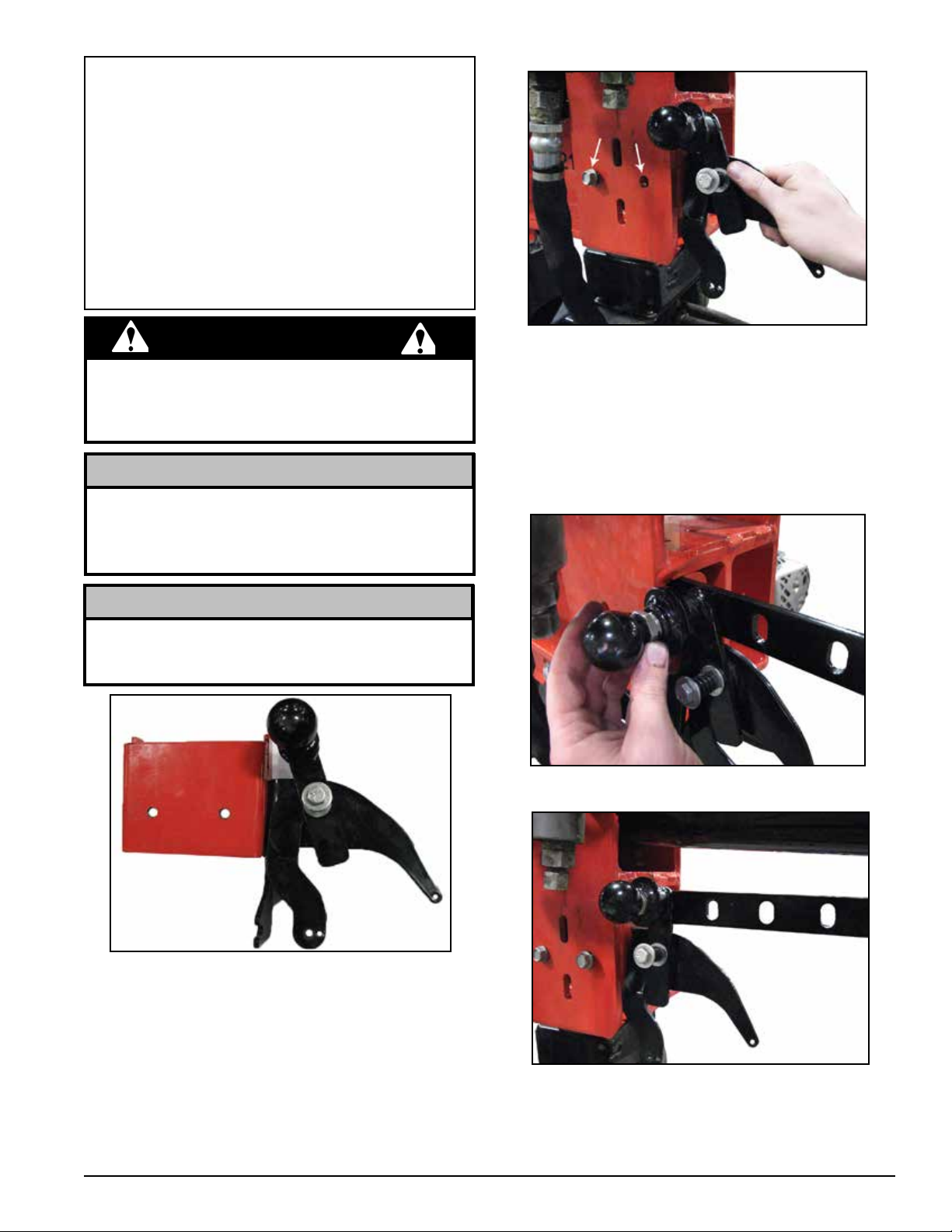
Figure 2. Channel and angle mount assembly
2. Do not completely tighten bolts at this point. Allow
enough movement to assist in completion of
assembly
3. Pull knob on angle mount assembly out to install slider
plate into channel mount as shown in Figures 3 and
4.
Figure 3. Pull knob out to install slider plate
Figure 1. Channel and angle mount assembly
INSTALLATION
1. Install the channel and angle mount assembly on the
right side of the log splitter in the channel with two
3/8 x 3/4" self-tapping hex bolts. IMPORTANT: If your
log splitter does not have the hex bolt holes already
pre-drilled, see Appendix 1 on page 8 for drilling
instructions.
Figure 4. Slider plate installed
PN 36323-00
Rev. 010112
Page 2
4. Continue to hold knob out and push the slider plate
through the channel and angle mount assembly,
Figure 5. Push slider plate through channel mount
5. Put a 1/4 x 3/4" hex bolt and nylock nut through the
hole on the end of the slider plate as shown in Figure
6.
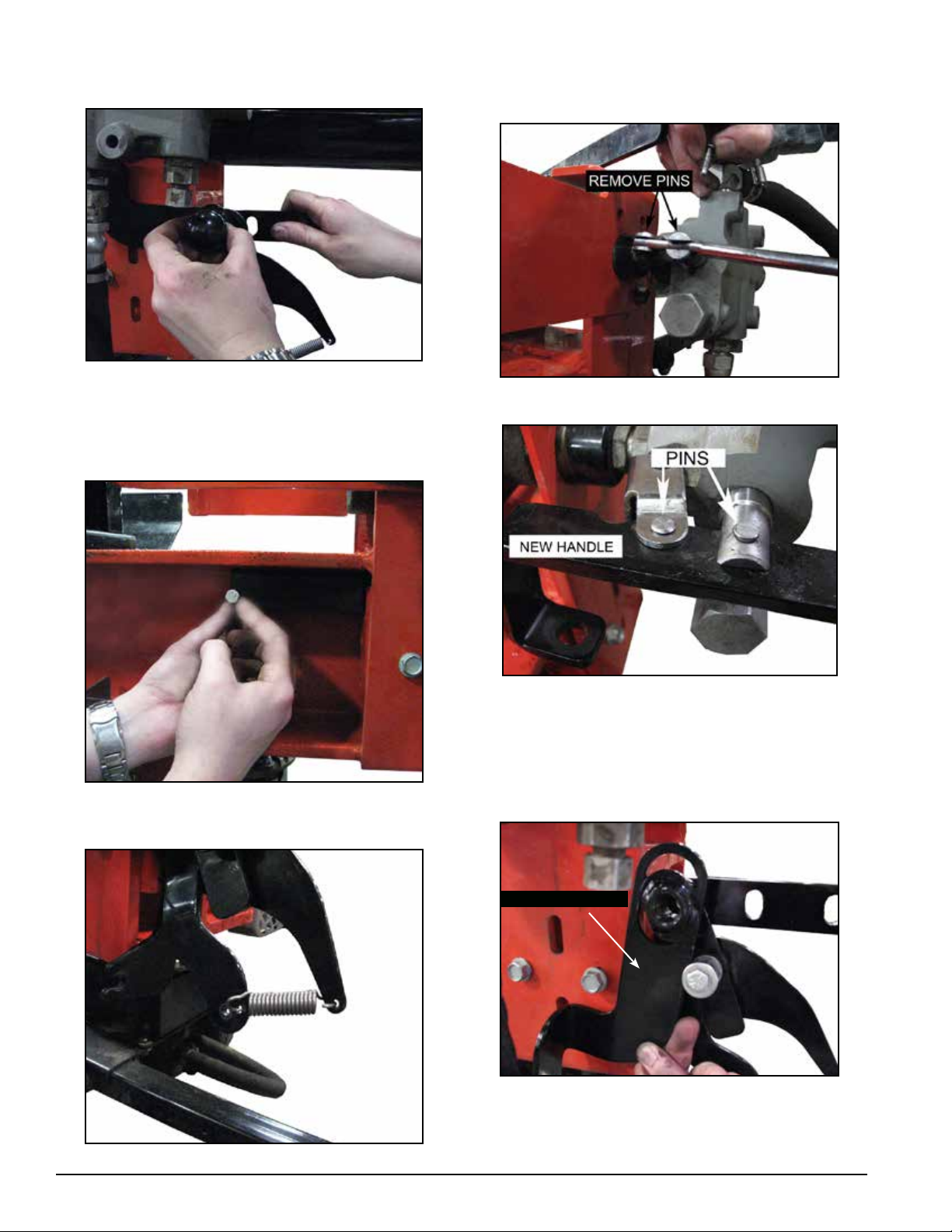
7. Remove the existing valve handle by removing the
two pins and cottter pins that attach it to the hydraulic
valve.
Figure 8. Pins to be removed on existing handle
Figure 6. Slider plate bolt location
6. Install spring on angle assembly. See Figure 7.
Figure 7. Properly installed spring
2
Figure 9. Pins to be installed on new handle
8. Replace it with the new handle from the kit and reinstall
original pins and cotter pins to secure.
9. Remove knob from angle mount to allow the installation
of the slide angle.
SLIDE ANGLE
Figure 10. Install slide angle with knob removed
10. Reinstall lever knob once slide angle is properly
installed.
Instruction Sheet
Page 3
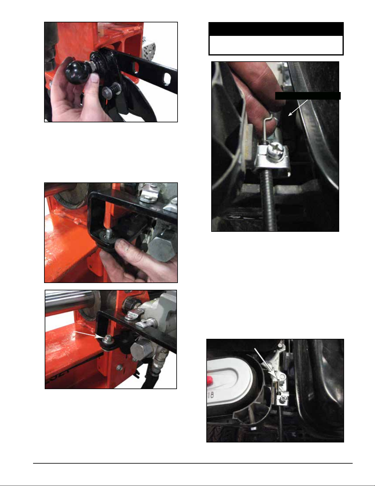
Figure 11. Reinstall lever knob
11. Pivot the end of the newly installed slide angle up and
align it with the end of the new handle. Attach them
using 5/16 x 1" hex head bolt, two washers and one
nylock nut. Tighten nut and bolt to the point that it still
allows proper operation of handle and slide angle.
NOTE
Steps 13 through 22 are not applicable to
Log Splitter models LS21 and LS21E.
CABLE CLAMP
Figures 12 & 12a. Connecting slide angle and new handle
12. At this point, verify that all parts of the assembly
are lined up and operating properly, and completely
tighten the 3/8 x 3/4" self-tapping hex bolts installed
in Step 1.
Figure 13. Throttle cable installed in cable clamp
14. Loosen the cable clamp located next to the throttle
control lever. Place the end of the throttle control cable
through the cable clamp.
15. Make sure several millimeters of cable insulation
are showing and tighten screw until snug. Do not
completely tighten.
16. Insert the "Z" end of the throttle cable into the small
diameter hole on the throttle lever as shown in Figure
13.
13. Remove the top of the air cleaner assembly to allow
better access for attaching the throttle cable end.
Instruction Sheet
Figure 14. "Z" end of cable inserted in throttle arm
3
Page 4

20. Remove the wire stop from the throttle cable by
loosening the bolt.
Figure 17. Coated clamp for routing of throttle cable
21. Attach the cable stop with a screw supplied with the
throttle cable, a #8 washer, and a 3/16" screw to the
lever bottom sheet. Tighten with an Allen head wrench
(the lever bottom must be in the vertical position).
Figure 15. Throttle arm friction nut
17. Loosen the friction nut (Figure 15) on the throttle lever
so the throttle lever moves freely and with very little
resistance. Failure to do this operation will not allow
the throttle cable to move the throttle lever properly or
with the full range of motion.
18. Make sure the throttle is in idle position.
19. Route the throttle cable through the 9/16 coated clamp
and install clamp on the lower right portion of the frame
using 1/4 x 3/4" bolt, washer and nut.
Figure 18. Cable stop mounting location and position
Figure 16. Coated clamp for routing of throttle cable
4
Instruction Sheet
Page 5

23. Remove the existing bottom wedge plate (A) as
shown in Figure 21, by removing the 1/2 nuts and
washers from the three 1/2 x 1-3/4" bolts securing it
to the wedge.
24. Install the new bottom wedge plate (B) that is supplied
in the Quick Split kit by reinstalling the bolts and
hardware, removed in step 23, and tighten securely.
A
Figure 19. Quick Split
22. Hook the spring between the lever bottom sheet and
the mount angle. On the quick split kit adjustment
may be necessary in order to achieve idle and full
throttle. Make adjustments at points (A) and (B) to
attain desired RPM settings. Ensure that the screw at
point (B) is not overtightened to the extent that the
cable stop will no longer pivot.
B
Figure 21. Installation of new cast wedge bottom plate(B)
OPERATION
QUICk SPLIT
1. Set the point to which the anvil will return by pulling the
ball out and adjusting the slider plate.
2. Move handle to split log.
3. After the log is split, push handle back and release. The
anvil will go back to the set point and then stop. The
engine will automatically throttle down.
THROTTLE DOWN
Figure 20. Throttle Down
1. Move handle to split log.
2. After the log is split, push handle back and release. The
anvil will go back to its original location and then stop.
The engine will automatically throttle down.
Instruction Sheet
5
Page 6

QUICk SPLIT kIT PARTS DIAGRAM
24
13
23
12
18
7
7
6
14
8
22
3
21
9
4
2
11
20
10
3
10
13
8
19
17
*Items 2, 6, 11 and 12 are not used in application on Log
Splitter models LS21 and LS21E
QUICk SPLIT kIT (PN 75896-00)
Item Part # Description Qty.
1 12177
2 14048-00 CLAMP, 9/16" COATED 1*
3 15001
4 15030 WASHER, 1/4 FLAT ZP 1
5 15140
6 15209 WASHER, #8 SAE 1*
7 15219
8 15250 WASHER, 5/16 FLAT ZP 5
9 15355 NUT, 1/4 NE NYLOCK ZP 2
10 15356 NUT, 5/16 NE NYLOCK ZP 2
11 15680-00
12 36088-00
6
SPRING, HEAVY DUTY
COMPRESSION
BOLT, 1/4 X 3/4 HEX HD
GR5 ZP
BOLT, 5/16 X 2 HEX HD GR5
ZP
BOLT, 5/16 X 1 HEX HD GR5
NC ZP
SCREW, #8-32 X 3/16 KNR
CUP PT
CABLE, THROTTLE LOG
SPLITTER
1
2
1
1
1*
1*
Instruction Sheet
5
16
15
13 36096-00
14 36387-00
15 75815-12 SHEET, LEVER BOTTOM 1
16 75843-12 ANGLE, MOUNT 1
17 75844-12 WELDMENT, LEVER 1
18 75849-12
19 75851-12
20 75890-12 ANGLE, SLIDE 1
21 75891-12
22 75925-12 CHANNEL, HANDLE 1
23 76015-35
24 77218-12
17320
1
8
BOLT, 3/8 X 3/4 SELF TAP
HEX ZP
SPRING, EXTENSION 1/2 X
2.00 X .075
PLATE, SLIDER QUICK
SPLIT
SPACER, 1/2 OD X 14 GA
X .36
SPACER, 1/2 OD X 14 GA
X .43
CHANNEL, MOUNT QUICK
SPLIT
PLATE, CAST WEDGE
BOTTOM
STRAP, 11 IN BLACK TIE
(NOT SHOWN)
4
1
1
1
1
1
1
1*
Page 7

THROTTLE DOWN kIT PARTS DIAGRAM
12
8
6
17
8
12
18
2
Throttle Down kit #75899-00 is not used on Log Splitter
models LS21 and LS21E
THROTTLE DOWN kIT (PN 75899-00)
Item Part # Description Qty.
1 14048-00 CLAMP, 9/16" COATED 1
2 15001
3 15030 WASHER, 1/4 FLAT ZP 1
4 15209 WASHER, #8 SAE 1
5 15219
6 15250 WASHER, 5/16 FLAT ZP 4
7 15355 NUT, 1/4 NE NYLOCK ZP 1
8 15356 NUT, 5/16 NE NYLOCK ZP 2
9 15436
10 15680-00
BOLT, 1/4 X 3/4 HEX HD GR5
ZP
BOLT, 5/16 X 1 GR5 HEX HD
NC ZP
BOLT, 5/16 X 1-1/4 HEX HD
GR5 NC ZP
SCREW, #8-32 X 3/16 KNR
CUP PT
1
1
1
1
Instruction Sheet
19
1
16
3
15
14
4
10
7
11
11 36088-00
12 36096-00
13 36387-00
14 72985 SPACER, 1/2 X .135 1
15 75843-12 ANGLE, MOUNT 1
16 75845-12 LEVER, THROTTLE 1
17 75850-12
18 75891-12
19 76015-35
17320
CABLE, THROTTLE LOG
SPLITTER
BOLT, 3/8 X 3/4 HEX SELF
TAP ZP
SPRING, EXTENSION 1/2 X
2.00 X .075
PLATE, SLIDER THROTTLE
DOWN
SPACER, 1/2 OD X 14 GA X
.43
CHANNEL, MOUNT QUICK
SPLIT
STRAP, 11 IN BLACK TIE
(NOT SHOWN)
6
9
5
13
1
4
1
1
1
1
1
7
Page 8

APPENDIX 1
DRILLING HOLES IN THE MOUNT PLATE
If your log splitter does not have the two holes in the channel used to complete Step 1, use the dimensions below to drill
two .41" x .50" holes in the mount plate.
Ø .41 x .50
1.25”
2.50”
1.25”
3.25”
ECHO BEAR CAT
Phone: 701.282.5520 • Toll Free: 800.247.7335 • Fax: 701.282.9522
E-mail: service@bearcatproducts.com • sales@bearcatproducts.com
237 NW 12th Street, West Fargo, ND 58078-0849
www.bearcatproducts.com
 Loading...