

Page 1

15-21D-01
HCAS-2200
1
1
2
INTRODUCTION
We are constantly working on technical
improvement of our products. For this reason,
technical data, equipment and design are
subject to change without notice. All
specifications and directions in this SERVICE
DATA are based on the latest products
inf o r m ati o n a v ail a b l e at th e t i m e of
publication.
INDEX
CONTENTS
page
1 SERVICE INFORMATION ............................. 2
1-1 Specification .................................................. 2
1-2 Technical data ................................................ 3
1-3 Torque limits ............................................... 4
1-4 Special repairing materials ......................... 5
1-5 Service limits .............................................. 5
1-6 Special tools ............................................... 6
2 EMISSION ADJUSTMENT GUIDE ............... 7
2-1 General adjusting rules .............................. 7
2-2 Presetting idle adjust screw, L mixture needle
and H mixture needle ........................................ 7
2-3 Adjusting carburettor .................................. 8
Reference No. 15-21D-01
R E V I S E D : 2 0 0 6 0 6
ISSUED: 200603
Page 2

2
1 SERVICE INFORMATION
1-1 Specifications
Model HCAS-2200
Dimensions Length mm(in) 1695 (66.7)
Width mm(in) 250 (9.8)
Height mm(in) 234 (9.3)
Dry weight kg(lb) 6.4 (14.0)
Engine Type KIORITZ, air-cooled, two-stroke, single cylinder
Rotation Counterclockwise as viewed from the output end
Displacement cm3(in3) 21.2 (1.29)
Bore mm(in) 32.2 (1.27)
Stroke mm(in) 26.0 (1.02)
Compression ratio 5.9
Carburetor Type Rotary type : Diaphragm, horizontal-draught, with purge bulb
Model ZAMA RB-K75
Ignition Type CDI (Capacitor discharge ignition) system
Spark plug BPMR8Y
Exhaust Muffler type Spark arrestor muffler
Starter Type Automatic rewind
Rope diameter x length mm(in) 3.0 x 1000 (3.0 x 39.5)
Fuel Type Premixed two-stroke fuel
Mixture ratio 50 : 1 (2%)
Gasoline Minimum 89 octane
Two-stroke engine oil ISO-L-EGD (ISO/CD13738), JASO FC
Tank capacity L (U.S.fl.oz.) 0.45 (15.2)
Clutch Type Centrifugal, 2-shoe pivot
Handle Type Front Loop type with hand guard
Drive shaft Type Flexible
Inner shaft : Diameter mm(in) 6.15 (0.24)
Inner shaft : Length mm(in) 864 (34.0)
Housing OD - ID - L mm(in) 25.0 - 22.0 (0.98 - 0.86)
(Main pipe) Length mm(in) 844 (33.2)
Gear case Reduction ratio 3.95
Gear tooth Spiral bevel gear
Lubrication Lithium based grease or ECHO LUBE
Cutter Type Double reciprocating, double edge blade
Length mm(in) 450 (18)
Pitch mm(in) 35.0 (1.38)
Height mm(in) 21.0 (0.83)
Thickness mm(in) 2.5 (0.098)
OD: Outer diameter.
ID: Inner diameter.
SERVICE INFORMATION
Slope advance ignition
combined with electronic speed governor
Rear Rubber grip with throttle trigger
system
HCAS-2200
TM
Page 3

HCAS-2200
1-2 Technical data
Engine
Idling speed r/min 2700 - 3200
Wide open throttle speed r/min 9500 - 11500
Clutch engagement speed r/min 3700 - 4300
Compression pressure MPa (kgf/cm2) (psi) 0.72 (7.3) (104)
Ignition system
Spark plug gap mm(in) 0.6 - 0.7 (0.024 - 0.028)
Primary coil resistance Ω 300 - 400
Minimum secondary voltage at 1500 r/min kV 15.0
Secondary coil resistance kΩ 2.4 - 3.2
Pole shoe air gaps mm(in) 0.30 - 0.40 (0.012 - 0.016)
Ignition timing at 1000 r/min °BTDC 19.0
at 8500 r/min °BTDC 42.0
at 11500 r/min °BTDC 14.0
Carburettor
Venturi Size mm(in) 9.0 (0.354)
Throttle Bore mm(in) 10.5 (0.413)
Idle adjust screw initial setting turn in* 2 1/2
L mixture needle initial setting turn back 2
H mixture needle initial setting turn back 2
Test Pressure, minimum MPa (kgf/cm2) (psi) 0.05 (0.5) (7.0)
Metering lever height mm(in) 0.1 - 0.25 (0.004-0.01) lower than diaphragm seat
BTDC: Before top dead center.
* Set idle adjust screw to contact throttle plate before initial setting.
SERVICE INFORMATION
3
Page 4

4
1-3 Torque limits
Descriptions Size kgf•cm N•M in•lbf
Starter
system
Starter case
Ignition Ignition coil M 4* 45 - 55 4.5 - 5.5 40 - 48
system
Fuel Carburettor M 5 26 - 37 2.6 - 3.7 22 - 32
system
Clutch Clutch hub M 8 180 - 220 18 - 22 160 - 200
Engine Crankcase M 5** 70 - 110 7 - 11 60 - 95
Regular bolt, nut, M 3 6 -10 0.6 - 1.0 5 - 9
and screw
Ignition switch M 4 30 - 40 3 - 4 26 - 35
Fan cover M 4 30 - 40 3 - 4 26 - 35
Spark plug M 14 150 - 170 15 - 17 130 - 150
Intake insulator M 5 26 - 37 2.6 - 3.7 22 - 32
Fuel tank M 5 26 - 37 2.6 - 3.7 22 - 32
Cylinder M 5** 70 - 110 7 - 11 60 - 95
Cylinder cover M 4* 22 - 32 2.2 - 3.2 20 - 28
Muffler M 5* 90 - 110 9 - 11 80 - 95
SERVICE INFORMATION
M 4* 45 - 55 4.5 - 5.5 40 - 48
M 4 15 -25 1.5 - 2.5 13 - 22
M 5 25 -45 2.5 - 4.5 22 - 40
M 6 45 -75 4.5 - 7.5 40 - 65
M 8 110 -150 11 - 15 95 - 130
HCAS-2200
*Apply thread locking sealant. (See below)
** The torque differences among bolts should not exceed 20 kgf•cm (2N•m, 17in•lbf) on one cylinder or crankcase.
1-4 Special repairing materials
Material Location Remarks
Grease Drive shaft
Gear case
Rewind spring
Starter center post
Oil seal inner lips
Thread locking Starter case
sealant
Cylinder cover (Starter side)
Ignition coil
Muffler
Lithium based grease or ECHO LUBE
Loctite #222, ThreeBond #1342 or equivalent
Loctite #675 or equivalent
TM
Page 5
HCAS-2200
0
5
1
2
3
4
5
6
7
8
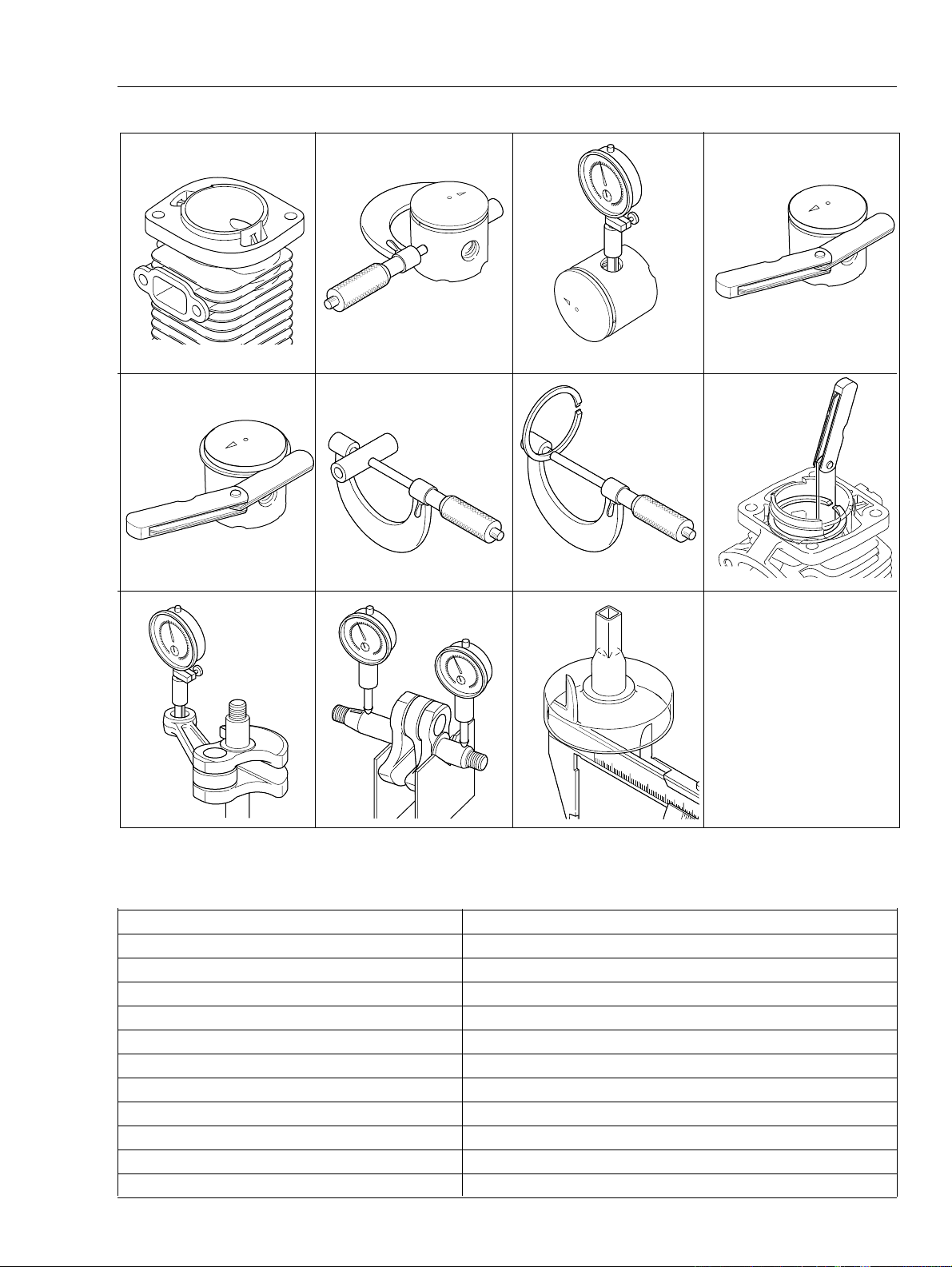
1-5 Service limits
SERVICE INFORMATION
5
5K286
5K266
5K219
5K263 5K264 5K265
5K016
5K171
5K017
5K071A
5K267
Description mm (in)
Cylinder bore When plating is worn and aluminum can be seen
Piston outer diameter Min. 32.10 (1.264)
Piston pin bore Max. 8.030 (0.3161)
Piston ring groove Max. 1.6 (0.063)
Piston ring side clearance Max. 0.1 (0.004)
Piston pin outer diameter Min. 7.970 (0.3138)
Piston ring width Min. 1.45 (0.057)
Piston ring end gap Max. 0.5 (0.02)
Con-rod small end bore Max. 12.000 (0.4724)
Crankshaft runout Max. 0.05 (0.002)
Clutch drum bore Max. 51.5 (2.03)
Page 6
6
20
40
60
80
120
140
160
180
20
100
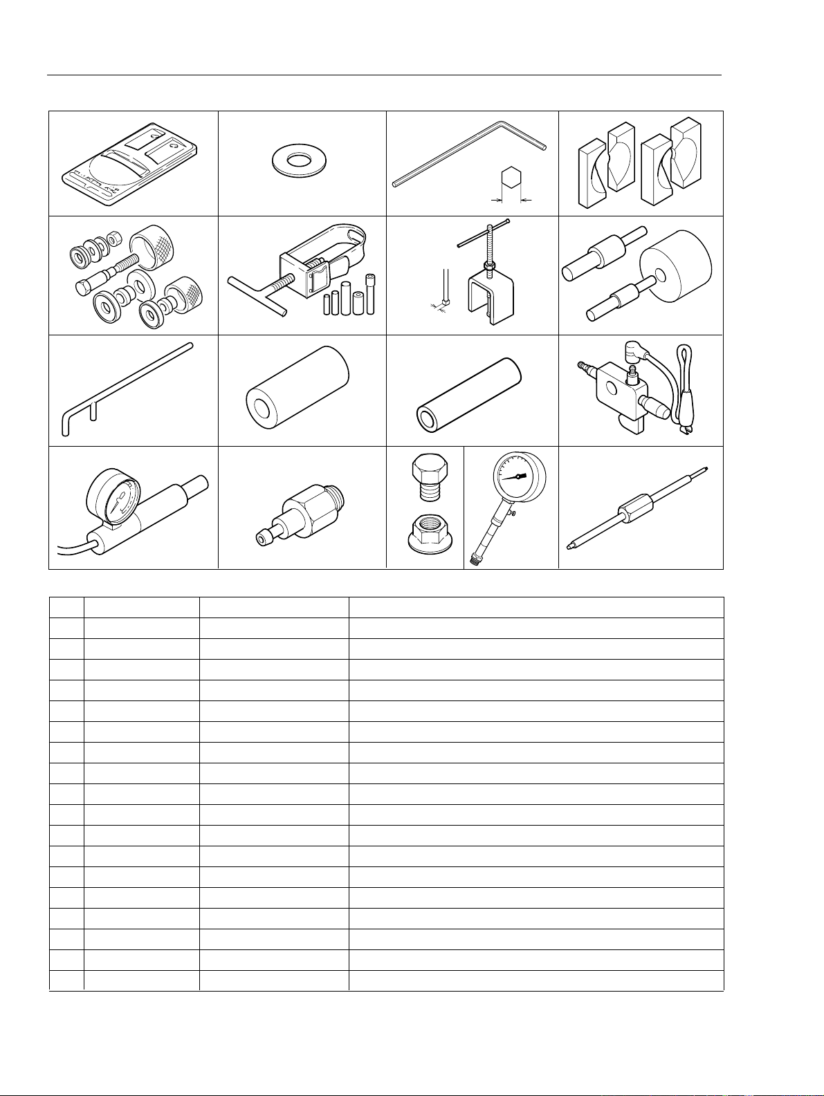
1-6 Special tools
1
SERVICE INFORMATION
2
3
4
HCAS-2200
a
5
6
7
8
5.3
9
13
10
14
11
15
16
17
8
0
1
6
0
4
0
2
0
12
0
0
18
1
2
0
1
4
0
1
6
0
1
8
0
2
0
0
2
0
1
9
Key Part Number Description Used for:
1 897801-33330 Tachometer PET-1000 Measuring engine speed
2 363018-00310 Washer Installing crankcase oil seal of starter side
3 895610-79920 L-hex wrench (4 mm) Removing and installing hex. socket bolts (M5)
4 897603-23030 PTO shaft puller Removing driven (PTO) shaft
5 897701-06030 Bearing wedge Removing ball bearings on crankshaft
6 897701-14732 Bearing tool Removing and installing crankcase ball bearings
7 897701-06030 Puller Removing drive gear assembly
8 897705-11520 Bearing tool removing and installing con-rod small end needle bearing
9 897712-04630 2-pin wrench Removing and installing pawl carrier
10 897726-16431 Oil seal tool Installing crankcase oil seals
11 897726-09130 Oil seal tool Removing clutch drum and installing clutch drum ball bearing
12 990511-30023 Spark tester Checking ignition system
13 897803-30133 Pressure tester Checking carburetor and crankcase leakages
14 91009 Retaining ring pliers Removing and installing retaining ring
15 900100-08008 Bolt Removing magneto rotor (flywheel)
16 433019-12330 Flange nut Removing magneto rotor (flywheel)
17 91007 Compression gauge Measuring cylinder compression
18 91020 Limiter plug tool Removal and installing limiter plug
Page 7
HCAS-2200
2 EMISSION ADJUSTMENT GUIDE
2-1 General adjusting rules
A. Before starting the unit for adjustment, check the following items.
1. The correct spark plug must be clean and properly gapped.
2. The air filter element must be clean and properly installed.
3. The muffler exhaust port must be clear of carbon.
4. The fuel lines, tank vent and fuel filter are in good condition and clear of debris.
5. The fuel is fresh ( > 89 octane : RON) and properly mixed at 50 : 1 with “ISO L-EGD” or “JASO FC” 2stroke oil.
6. The gear case assembly with blade set adjusted clearance properly must be installed for proper engine
loading.
B.
Start and run engine for 2 minutes alternating engine speed between WOT and idle every 5 seconds.
Adjust idle adjust screw to 2900 +/- 200 r/min. If engine does not run correctly after this adjustment, proceed
to the next step
IMPORTANT : After adjusting carburettor according to the steps 2-2 and 2-3, the limiter plug(s) must be
installed on Idle and H mixture needle(s) hole(s) to comply with Emission Directive.
(2-2).
SERVICE INFORMATION
7
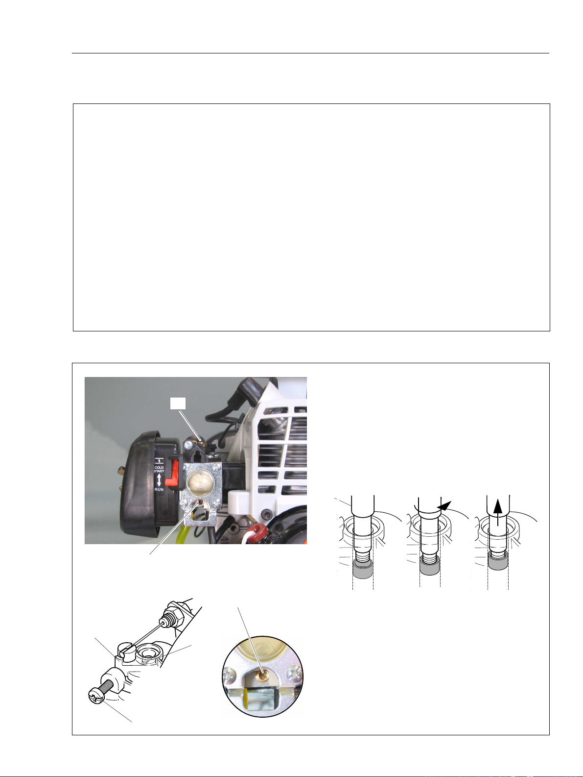
2-2 Presetting idle adjust screw, idle mixture needle and H mixture needle
1. Remove plugs from idle mixture needle hole (A)
and H mixture needle hole (B) using limiter plug tool
(A)
(C) as shown.
(1) Put limiter plug tool (C) on limiter plug in needle hole.
(2) Screw limiter plug tool anticlockwise 2 turns into limiter
plug.
(3) Pull out limiter plug tool with the limiter plug from
needle hole.
(1)
(C)
(B)
(F)
(G)
(D)
NOTE : When plug is damaged and left in the hole,
use needle or pin-shaped tool to scrape.
2. Turn idle mixture needle (D) and H mixture needle
(G) clockwise until lightly seated. And then turn out
both needles following turns.
(2)
(3)
(E)
Idle mixture needle : 2 H mixture needle : 2
3. Turn idle adjust screw (E) anticlockwise until its
tip just touches throttle plate (F). Then turn it in
clockwise 2 1/2 turns.
Page 8

8
2-3 Adjusting carburettor
SERVICE INFORMATION
HCAS-2200
1. Start engine and warm it up
speed between WOT and idle every 5 seconds for
1 minute
2. Adjust idle mixture needle and obtain maximum
idle speed with 2.5 mm blade small screw driver.
3. Set idle speed to 3,500 r/min by turning idle adjust
screw.
4. Turn idle mixture needle anticlockwise to reduce
idle speed 500 to 750 r/min in the range of 2,750 to
3,000 r/min.
NOTE : Engine speed must be allowed to stabilize
a minimum of 20 seconds after each adjustment of
L mixture needle to assure accurate tachometer
readings.
5. Adjust H mixture needle and obtain maximum
WOT engine speed.
.
alternating engine
(E)
(F)
(F)
6. Turn H mixture needle anticlockwise to reduce
WOT engine speed 100 r/min.
7. Restart engine again and make sure engine runs
in the range of 2,700 to 3,200 r/min at idling and the
range of 9,500 to 1 1,500 r/min at WOT. Also make it
sure cutting device would not move at engine idle
speed and suitable acceleration.
8. After adjusting carburettor, insert and secure new
plug(s) (F) P005-001270 deep in the needle holes
per the Emission regulation using limiter plug tool (E).
NOTE : Initial carburettor setting (idle adjust screw,
idle and H mixture needles) shown on page 3 and 7
is to start the engine after restoration or carburettor
change. Idle adjust screw, idle and H needles turn
for designated engine revolution through procedures
indicated here may vary. As long as idle and WOT
engine speed is set in given range, variance would
be ignorable.
 Loading...