

Page 1

OPERATOR'S MANUAL
ES-2100ESL
LEAF SHREDDER
X7531138201
08/10
WARNING, READ OPERATOR'S MANUAL
Page 2

INTRODUCTION
The ECHO ES-2100ESL SHRED-N-VAC™ are lightweight,
high performance, petrol powered units designed for vacuuming and processing a wide variety of fallen leaves and cut
lawn. Also this unit is easily converted to a blower.
This Manual provides the information necessary for operation and maintenance. Read it carefully to familiarize yourself with the operating of your ECHO product.
WARNING DANGER
READ AND UNDERSTAND THE RULES FOR
SAFE OPERATION AND ALL INSTRUCTIONS IN
THIS MANUAL.
WEAR EYE AND HEARING PROTECTION.
IMPROPER USE OR CARE OF THIS UNIT, OR
FAILURE TO WEAR PROPER PROTECTION
CAN RESULT IN SERIOUS INJURY.
Introduction ...............................................................................................................................................................2
Safety and special information .................................................................................................................................2
Rules for safe operation ...........................................................................................................................................3
Description................................................................................................................................................................5
Assembling ...............................................................................................................................................................7
Operation ..................................................................................................................................................................8
Maintenance and care ............................................................................................................................................11
Troubleshooting ......................................................................................................................................................15
Storage ...................................................................................................................................................................16
Specifications .........................................................................................................................................................17
Decals and symbols ...............................................................................................................................................17
Specifications, descriptions and illustrative material in this literature are as accurate as known at the time of publication, but
are subject to change without notice. Illustrations may include optional equipment and accessories, and may not include all
standard equipment.
CONTENTS
SAFETY AND SPECIAL INFORMATION
Circle and slash symbol means
WARNING DANGER
THIS SYMBOL IS USED TO CALL
ATTENTION TO PROCEDURES THAT
MUST BE FOLLOWED TO AVOID THE
RISK OF SERIOUS, IMMEDIATE AND
IRREVERSIBLE HUMAN INJURY OR DEATH.
CAUTION
CAUTION indicates a potentially hazardous situation, if not avoided, may result in minor or moderate
injury.
whatever is shown is prohibited.
NOTE
This enclosed message provides tips for use, care
and maintenance of the unit.
• Read and understand the entire operator's manual
before using this machine.
• Follow all danger warnings in this manual.
• Locate the safety decals on your unit. Make sure the
decals are legible and that you understand and follow
them.
2
Page 3

RULES FOR SAFE OPERATION
WARNING DANGER
USERS RISK INJURY TO THEMSELVES AND OTHERS IF THE UNIT IS USED IMPROPERLY, AND/OR
SAFETY PRECAUTIONS ARE NOT FOLLOWED.
PROPER CLOTHING AND SAFETY GEAR MUST BE
WORN WHEN OPERATING THIS UNIT.
OPERATOR SAFETY
• Read this Manual carefully. Be sure you understand how
to operate this unit properly before you use it.
• Wear non-skid sole shoes. Do not wear open-toed shoes
or operate unit while bare footed.
• Wear proper clothing to protect legs and other
exposed parts of your body.
• Wear eye, breathing and hearing protection devices.
• Secure hair so it is above shoulder height.
• Use caution when handling fuel. The fuel tank may
be under pressure. Always loosen the fuel cap and wait
for pressure to be equalized before removing
the cap. Put the fuel cap back tightly on both the fuel
can and the fuel tank.
• Move at least 3 m from the refuelling point and be sure
there is no leakage of fuel from the fuel cap
or the fuel system before starting the engine.
• Wipe any spilled fuel off the unit.
• Operate this petrol engine powered equipment in a well
ventilated area only.
• Do not operate this unit in closed areas such as garages,
inside buildings, sheds, etc.
• Start the unit on the ground with the throttle set at idle.
• Do not start if the pipe is obstructed by the ground or any
other object.
• This unit is not designed as a limb shredder or chipper.
Branches and debris should not be sucked in.
• Inspect area where the unit is to be used.
• Remove stones, metal objects and any other object that
could cause injury or damage unit.
• Do not use a unit on unstable surfaces.
• Do not allow other persons or pets in the area when starting or using the unit.
• Do not point pipes or tube in the direction of people or
animals.
• Keep a firm grip on the unit at all times.
• Be certain the safety interlock switch operates correctly
(unit must stop when vacuum tube is removed or fan
guard is opened).
• Keep hands and body away from hot surfaces such as
silencer and cylinder area when handling the unit to
prevent from heat injury.
• Never attempt to use an incomplete machine or one
fitted with unauthorized modification.
• Never allow children to use the machine.
REDUCE NOISE - BE SMART!
NOTE
Before operating the unit, check and follow local regulations concerning sound level and hours of operation.
• Avoid using power units when people are likely to be
disturbed, such as late at night or early in the morning.
As a rule, operate units between 9 a.m. and 5 p.m. on
weekdays and weekends.
• Operate the unit at the lowest possible throttle setting
that gets the job done.
• Make sure the silencer works well.
• Check the air intakes and the air filter to make sure the
unit is working properly.
• Use only one piece of equipment at a time.
• Wear hearing protection when operating the unit.
• Be a good neighbor. Keep debris on your property.
SP ARK ARRESTER SILENCER
The spark arrester silencer controls the exhaust noise and
prevents hot, glowing particles of carbon from leaving the
unit.
Make sure the spark arrester screen is in good repair and
properly seated in the silencer.
PHYSICAL CONDITION
Your judgement and/or dexterity may be impaired if you are
ill, are taking medication, and/or have taken alcohol or other
substances known to affect the way you would normally
function.
Operate this unit only if you are in good physical and mental
health.
3
Page 4

HOT HUMID WEATHER
Heavy protective clothing can increase operator fatique
which may lead to heat stroke. Delay heavy work until the
temperature drops.
VIBRA TION AND COLD
It is believed that a condition called Raynaud's Phenomenon, which affects the fingers of certain individuals may
be brought about by exposure to vibration and cold. Exposure to vibration and cold may cause tingling and burning,
followed by loss of color and numbness in the fingers. The
following precautions are strongly recommended because
the minimum exposure which might trigger the ailment is
unknown.
• Keep your body warm, especially head and neck, feet and
ankles and hands and wrists.
• Maintain good blood circulation by performing vigorous
arm exercises during frequent work breaks and also by
not smoking.
• Limit the number of hours operation. Try to fill each day
with jobs where operating the unit or other hand-held
power equipment is not required.
• If you experience discomfort, redness and swelling of the
fingers followed by whitening and loss of feeling, consult
your physician before further exposing yourself to cold
and vibration.
REPETITIVE STRESS INJURIES
• It is believed that overusing the muscles and tendons of
the fingers, hands, arms and shoulders may cause sore-
ness, swelling, numbness, weakness and extreme pain to
the areas just mentioned.
EYE AND HEARING PROTECTION
• Wear eye protection goggles.
• Wear hearing protection. If this guideline is not followed,
hearing loss can occur.
WEAR PROPER CLOTHING
• Snug fitting, durable clothing should be worn. Trousers
should have long legs. DO NOT WEAR SHORTS.
• Do not wear loose fitting clothing, scarfs, neckties, jewelry
or any item that may be drawn or tangled in the fan.
• Wear shoes with non-skid soles. DO NOT wear open-toed
shoes or operate unit bare footed.
• Wear no-slip, heavy work gloves to improve your grip on
the handles. The gloves also help reduce the transmission
of machine vibration to your hands.
Certain repetitive hand activities may put you at a high risk
developing a repetitive stress injury (RSI).
To reduce the risk of RSI, do the following:
• Avoid using your wrist in a bent, extended or twisted position.
• Take periodic breaks to minimize repetition and rest your
hands.
• Reduce the speed and force in which you do the repetitive
movement.
• Do exercises to strengthen hand and arm muscles.
• See a doctor if you feel tingling, numbness or pain in your
fingers, hands, wrists or arms.
The sooner RSI is diagnosed, the more likely permanent
nerve and muscle damage can be prevented.
4
Page 5

DESCRIPTION
CONTENTS
1 - Power Head
1 - Blower Pipe Assembly
1 - Shred 'N' Vac Suction Tube
1 - Vacuum Bag
1 - Operator's Manual
1 - T-Wrench
10
12
1
3
11
6
7
5
15
16
14
4
13
7
2
OPERATOR'S MANUAL
WARNING, SEE OPERATOR'S MANUAL
S
AFETY DECALS
X7531138200
Locate these safety decals on your unit. Make sure
the decals are legible and that you understand and
follow the instructions on them. If a decal cannot be
read, a new one can be ordered from your ECHO
dealer.
8
ES-2100ESL
LEAF SHREDDER
17
5
15
9
P/N 89016006361
P/N 89016009461
5
Page 6

DESCRIPTION
1. SPARK PLUG - Provides spark to ignite fuel mixture.
2. THROTTLE POSITION LEVER - Pull back to increase engine speed. Friction washers maintain throttle trig-
ger setting.
3. SILENCER/SP ARK ARRESTER - The spark arrester muffler controls the exhaust noise while the spark ar-
rester prevents hot, glowing particles of carbon from leaving the muffler.
4. FUEL TANK CAP - For closing the fuel tank.
5. CHOKE LEVER - Lever is located on right side of the air cleaner. Move lever DOWN to close choke (starting
position) and for emergency stopping. Lift up to open choke (run position).
6. AIR CLEANER - Contains replaceable felt element.
7. IGNITION SWITCH - "SLIDE SWITCH" mounted on top of handle. Slide forward to start and run. Slide back
to stop.
8. THROTTLE TRIGGER - Spring loaded to return to idle when released if throttle position lever is not en-
gaged.
9. BLOWER PIPES - Twist lock design.
10. VACUUM PIPE - Sucks in materials to be shredded.
11. VACUUM ELBOW - Discharges shredded material.
12. VACUUM BAG - Collects shredded material.
13. SHOULDER STRAP - Secures debris bag to shoulder.
14. STARTER HANDLE - Pull handle slowly until starter engages, then return handle slowly. DO NOT let handle
snap back or damage to unit will occur.
15. PURGE BULB - Pumping purge bulb before starting draws fresh fuel from fuel tank to carburettor replacing
air and old fuel. Before starting, pump repeatedly (normally 3-4 times) until fuel is visible in "Clear" fuel return
line.
16. SIDE HANDLE - Provides grip for right hand.
17. HOUSING COVER - Covers blade area when closed.
6
Page 7

ASSEMBLING
NEVER PERFORM MAINTENANCE OR ASSEMBLY PROCEDURES WITH ENGINE RUNNING.
NOTE
Never operate unit without either fan grid and blower
pipes or vacuum tube with vaccum elbow and debris bag
are installed securely on the unit.
WARNING DANGER
Knob
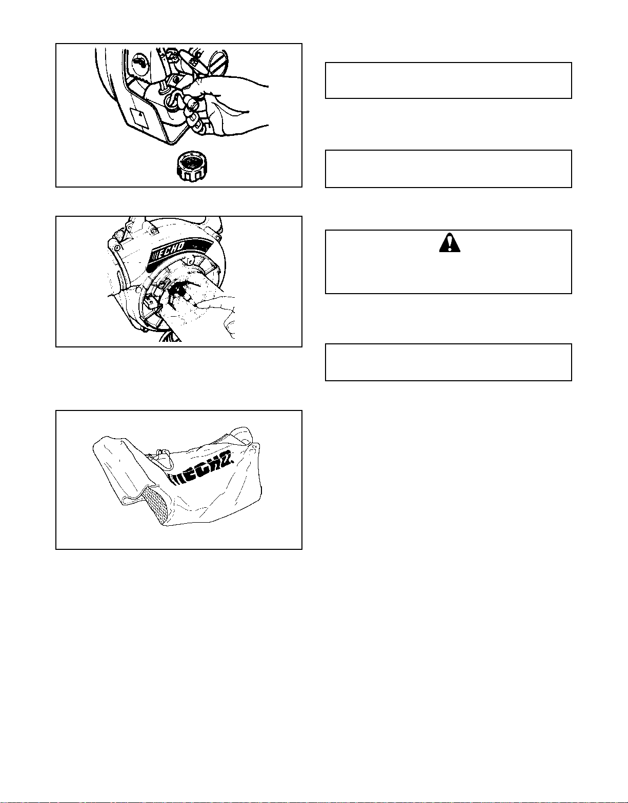
INSTALLING VACUUM TUBE FOR VACUUM USAGE
1. Turn knob anticlockwise until fan grid is free. Pull fan grid
out for access to tube clamp.
2. Loosen screw in clamp.
3. While holding housing cover open, align arrow on vacuum tube with interlock switch (D), and install vacuum
tube into blower housing. Secure vacuum tube with
clamp (B). Clamp fits under slotted guides (C).
C
B
D
C
NOTE
The tube will contact the safety interlock switch tab
when properly assembled onto the blower. A "click" will
be heard indicating the switch is activated allowing the
unit to operate. If the engine does not start, recheck the
tube mounting for straightness and engagement with the
blower housing.
4. Secure vacuum tube with clamp by tightening screw.
5. Remove tube retaining screw from blower housing. Align
grooves in vacuum elbow with pegs on air outlet and
install vacuum elbow.
6. Turn vacuum elbow clockwise to lock it into place, pointing backward, then tighten the screw securely.
7. Place vacuum bag opening over end of vacuum elbow
and secure with velcro strap.
WARNING DANGER
THIS UNIT IS EQUIPPED WITH A SAFETY
INTERLOCK SWITCH WHICH ALLOWS THE
ENGINE TO START OR RUN ONLY WHEN THE
FAN GUARD IS IN PLACE OR THE VACUUM
TUBE IS INSTALLED. NEVER BEND OR DISABLE THIS SWITCH AND OPERATE THE UNIT;
OTHERWISE SEVERE INJURY MAY RESULT.
7
Page 8

FUEL
INSTALLING BLOWER PIPES FOR BLOWER
USAGE
1. Remove tube retaining screw from blower housing.
Align grooves in straight pipe with pegs of blower
housing and slide pipe onto housing.
2. Turn straight pipe clockwise to lock it into place.
3. Tighten screw securely.
4. Remove tube retaining screw from the straight
tube. Align grooves in fan head nozzle with pegs
on
straight pipe and slide fan head nozzle onto
straight pipe.
5. Turn fan head nozzle clockwise to lock it into place.
6. Tighten the screw on fan head nozzle securely.
OPERATION
• Fuel is a mixture of regular grade petrol and an air-cooled
2-stroke engine oil of reputable brand name. Minimum
89 Octane unleaded petrol is recommended. Do not use
fuel containing methyl alcohol or more than 10 % of ethyl
alcohol.
• Recommended mixture ratio; 50 : 1 for ISO-L-EGD
Standard (ISO/CD 13738), JASO FC grade and ECHO
Premium 50 : 1 oil (2%).
WARNING DANGER
Fuel is VERY flammable. Use extreme care when
mixing, storing or handling or serious personal
injury may result.
• Use an approved fuel container.
• DO NOT smoke near fuel.
• DO NOT allow flames or sparks near fuel.
• Fuel tanks/cans may be under pressure. Always
loosen fuel caps slowly allowing pressure to
equalize.
• NEVER refuel a unit when the engine is HOT or
RUNNING!
• DO NOT fill fuel tanks indoors. ALWAYS fill fuel
tanks outdoors over bare ground.
• DO NOT overfill fuel tank. Wipe up spills immediately.
• Securely tighten fuel tank cap and close fuel
container after refueling.
• Inspect for fuel leakage. If fuel leakage is found,
do not start or operate unit until leakage is repaired.
• Wipe any spilled fuel from the unit. It is not premitted to fill fuel above the shoulder level of fuel
tank. (Shoulder level)
• Move at least 3 m from refuelling location before
starting the engine.
8
Page 9

Throttle lever
START/RUN
Minimum 3 m
Ignition switch
HANDLING FUEL
• Do not mix directly in engine fuel tank.
NOTE
Stored fuel ages. Do not mix more fuel than you expect
to use in thirty (30) days. Do not mix directly in fuel tank.
• Never store the unit with fuel in the tank - a fuel leak could
start a fire.
• Store fuel in a well ventilated, unoccupied building away
from sparks and flames.
STARTING COLD ENGINE
1. Move ignition switch to START/RUN position.
2. Move throttle lever to IDLE position.
NOTE
Starter handle: Use short pulls - only 1/2 - 2/3 of starter
rope for starting. Do not allow the rope to snap back in.
Always hold the unit firmly.
NOTE
Check unit for loose nuts, bolts and screws daily.
Choke lever
Ignition switch
Throttle lever
3. Push purge bulb until fuel is visible in clear fuel return
line.
4. Move choke lever up to closed position and pull starter
handle until the first firing sound.
5. Move choke lever down to open position.
Restart the engine to allow to warm up for a few minutes
before using.
STARTING WARM ENGINE
1. Move ignition switch to RUN position.
2. Move throttle lever toIDLEposition.
3. Move choke lever down to open position.
4. If fuel tank is not empty, pull starter one to three times
Purge bulb
C
B
and engine should fire. Do not use choke.
5. If fuel tank is empty, after refilling, push the purge bulb
until fuel is visible in clear fuel return line and then pull
the starter. Do not use choke.
NOTE
If engine does not start after 4 pulls, use cold starting
procedure.
STOPPING ENGINE
1. Release throttle trigger and allow engine to run at idle.
STOP
2. Move throttle lever to IDLE position.
3. Move ignition switch to STOP (downward) position.
WARNING DANGER
IF ENGINE DOES NOT STOP, SHIFT CHOKE
LEVER UP CLOSED POSITION. YOU MUST
HAVE YOUR ECHO DEALER INSPECT AND REPAIR IGNITION SWITCH BEFORE USING UNIT
AGAIN.
Throttle trigger
9
Page 10

OPERATING VACUUM
WARNING DANGER
• ALW A YS WEAR SAFETY GLASSES AND USE
A FACE FILTER MASK. (READ THE SAFE
OPERATION CAREFULLY.)
• DO NOT POINT VACUUM TUBE IN THE
DIRECTION OF PEOPLE OR PETS.
Throttle position lever
NOTE
Do not block vacuum pipe to avoid engine damage due to
over speed.
NOTE
Never use a higher speed setting than necessary to perform of task. Remember, the higher the engine speed, the
louder the vacuum noise.
1. Allow the engine to warm up at a fast idle for a few minutes.
2. Set engine speed with throttle position lever.
3. Place shoulder harness over right shoulder.
4. Make sure bevel at end of vacuum tube faces
downward.
5. Hold and guide Shred 'N' Vac with both hands clasped
firmly on side and top handles. Keep unit to your right
side.
OPERATING BLOWER
WARNING DANGER
• ALW A YS WEAR SAFETY GLASSES AND USE
A FACE FILTER MASK. (READ THE SAFE
OPERATION CAREFULLY.)
• DO NOT POINT THE BLOWER PIPE IN THE
DIRECTION OF PEOPLE OR PETS.
• NEVER OPERATE UNIT WITHOUT FAN GRID
SECURED BY THUMB NUT OTHERWISE
BODILY HARM MAY RESULT.
NOTE
Do not block blower pipe to avoid engine damage due to
over speed.
1. Allow the engine to warm up at a fast idle for a few minutes.
2. Engine speed can be easily controlled by throttle trigger
with fingers or throttle position lever.
NOTE
Never use a higher speed setting than necessary to perform a task. Remember, the higher the engine speed, the
louder the blower noise.
NOTE
Use lower speed to clean grass and leaves from walks,
patios and drives. Additional speed may be necessary to
blow dry leaves from a lawn or flower bed. Higher speed
may be necessary to move gravel, dirt, snow, bottles or
cans from a driveway, street, parking lot or stadium.
10
Page 11

REDUCE CHANCES OF DAMAGE
• Before starting the job, check wind direction. Avoid blowing in the direction of open doors and windows, cars, pets,
children or anything that could be harmed by blowing
dust, leaves and debris.
• Use the full nozzle extension so the air stream is close to
the ground. This will get the job done quicker without kicking up a lot of dust.
• In dusty conditions, wet down surfaces to prevent blowing
up dust.
• Clean up after the job is done. Make sure no debris has
blown onto someone else's property. Collect any trash
and put it in a proper container.
AREA MAINTENANCE PAGE BEFORE USE MONTHLY
MAINTENANCE AND CARE
Air Filter Inspect/Replace 12 •
Fuel Filter Inspect/Clean/Replace 14 •
Fuel Line Inspect - •
Spark Plug Inspect/Clean/Adjust/Replace 13 •
Carburettor Adjust 12 •
Cooling System Inspect/Clean 13 •
Silencer (Spark arrester) Inspect/Tighten/Clean 13 •
Starter Rope Inspect/Replace - •
Fuel System Inspect/Repair - •
Vacuum Bag Inspect/Clean 14 •
Processing Device Inspect/Clean 14 •
Screws, Bolts and Nuts Inspect, Tighten/Replace - •
IMPORTANT: Time intervals are maximum. Actual use and your experience will determine the frequency of required maintenance.
11
Page 12

CLEANING AIR FILTER
NOTE
Clean daily.
1. Close choke, remove wing stud, air cleaner cover and air
filter.
2. Brush dust off filter and wash in suitable solvent.
3. Dry filter before reinstalling.
ADJUSTING CARBURETTOR
GENERAL
NOTE
Do not adjust carburettor unless necessary. If you have
trouble with carburettor, see your dealer. Always adjust
carburetor with pipes assembled to the unit.
ADJUSTERS
Idle Speed Adjuster (T) Control throttle opening at
Low Speed Mixture Adjuster (L) Controls amount of fuel
L
H
High Speed Mixture Adjuster (H) Controls amount of fuel at
idle.
at low speed and
supplementary fuel for
smooth progression
from idle to high speed.
full throttle
T
L
H
T
NOTE
When there is some trouble with the carburettor, contact
your distributor or dealer.
BEFORE ADJUSTMENT
Check that:
- Air filter is clean and properly installed.
- Spark arrestor screen and exhaust port are free of carbon.
- Blower pipes are installed.
INITIAL ADJUSTMENT
1. With engine off, turn H adjuster anticlockwise to stop.
2. Turn L adjuster midway between stops.
3. Turn T adjuster until tip of adjuster just touches throttle
plate; then turn three turns clockwise.
FINAL ADJUSTMENT
IMPORTANT
Limiter caps prevent exceeding emission limits and
over rich adjustment, but not over lean adjustment,
which can cause engine failure: Do not exceed recommended high speed engine rev during operation,
or for long periods during adjustment.
1. Start engine, run at idle for one minute.
2. Complete warm up by running at full throttle for 5 min-
utes, operating choke twice to clear air from carburettor
chambers.
3. Run at idle and accelerate to check for smooth transi-
tion from idle to high speed; if engine hesitates, turn L
adjuster anticlockwise 1/8 turn at a time until acceleration
is smooth.
4. Adjust T adjuster to 2,400 - 3,200 r/min, using tachom-
eter.
12
Page 13

SPARK PLUG
1. Check plug gap. Correct gap is 0.6 - 0.7 mm.
2. Inspect electrode for wear.
3. Inspect insulator for oil or other deposits.
4. Replace plug if needed and tighten to 15 - 17 N·m (150
to 170 kgf·cm).
0.6 - 0.7 mm
NOTE
Do not overtighten spark plug.
COOLING SYSTEM MAINTENANCE
NOTE
To maintain proper engine operating temperatures, cooling
air must pass freely through the cylinder fin areas. This
flow of air carries combustion heat away from the engine.
Overheating and engine seizure can occur when:
• Air intakes are blocked preventing cooling air from reaching the cylinder, or
• Dust and grass build up on the outside of the cylinder.
This build up insulates the engine and prevents the heat
from leaving.
Removal of cooling passage blockages or cleaning of
cylinder fins is considered "Normal Maintenance." Any
resultant failure attributed to lack of maintenance is not
warranted.
The cooling system relies on cooling air entering the engine
through a grille located between the fuel tank and starter.
The cooling fan pushes this air through the cylinder area
and out the forward facing opening in the engine cover.
Intake grille
Exhaust diffuser
Spark arrester cover
Screen
Gasket
Remove accumulated debris from intake grille for cleaning.
SILENCER AND EXHAUST PORT
NOTE
Carbon deposits in cylinder exhaust port and silencer will
cause a drop in engine output and overheating. Silencer
exhaust port and screen must be checked.
1. Remove spark plug, engine cover, gasket and silencer.
2. Place piston at top dead center. Clean deposit from
silencer and cylinder exhaust port.
NOTE
Be careful not to scratch the cylinder or piston when cleaning the cylinder exhaust port.
3. Remove spark arrester cover, exhaust diffuser, gasket
and screen from silencer. Replace screen if plugged with
carbon deposits.
4. Inspect gaskets, replace if damaged.
5. Install spark arrester screen, gasket, diffuser and cover.
6. Install silencer, gasket and engine cover.
13
Page 14
REPLACING FUEL FILTER
NOTE
A clogged fuel filter will cause hard starting or poor engine
performance.
1. Pick up the fuel filter through fuel tank opening with a
piece of steel wire or the like.
2. Remove old filter from fuel line.
3. Install new fuel filter.
NOTE
Keep fuel tank clean - do not allow dirt or debris to enter
fuel tank.
PROCESSING DEVICE
WARNING DANGER
NEVER REMOVE VACUUM TUBE OR OPEN
FAN GUARD WHEN SHRED-N-VAC™ IS RUN-
NING.
1. With engine stopped, remove spark plug wire, loosen
clamp and pull vacuum tube from unit.
2. Remove accumulated debris from processing device and
inspect for damage.
NOTE
Do not operate SHRED-N-VAC™ if processing device is
damaged, loose or broken.
3. Refer to "Installing Vacuum Tube'' in assembly section
for correct reassembling procedures.
VACUUM BAG
Shake dust from bag and inspect for holes or tears.
Inspect zipper and clean debris from teeth to assure com-
plete closing of zipper.
14
Page 15

TROUBLESHOOTING
Trouble
Engine - starts hard Cause Remedy
- does not start
Engine Fuel at No fuel • Fuel filter clogged • Clean or replace.
Cranks carburettor at carburettor • Fuel line clogged • Clean.
• Carburettor • Ask your ECHO dealer.
Fuel at No fuel at • Carburettor • Ask your ECHO dealer.
cylinder cylinder
Silencer wet • Fuel mixture is • Open choke.
with fuel too rich • Clean/replace air filter.
• Adjust carburettor.
• Ask your ECHO dealer.
Spark at No spark at • Ignition switch off • Turn switch on.
end of end of plug • Electrical problem • Ask your ECHO dealer.
plug wire wire • Safety interlock • Tighten grid cover, check vacuum
not engaged tube attachment
Spark at No spark at • Spark gap incorrect • Adjust 0.6 to 0.7 mm
plug plug • Covered with carbon • Clean or replace.
• Fouled with fuel • Clean or replace.
• Spark plug defective • Replace plug.
Engine • Internal engine • Ask your ECHO dealer.
does not problem
crank
Engine Dies or • Air filter dirty • Clean or replace.
runs accelerates poorly • Fuel filter dirty • Clean or replace.
• Fuel vent plugged • Clean.
• Spark plug • Clean and adjust/replace.
• Carburettor • Adjust.
• Cooling system • Clean.
plugged
• Exhaust port/spark • Clean.
arrester screen
plugged
WARNING DANGER
Fuel vapors are extremely flammable and may cause fire and/or explosion. Never test for ignition spark by grounding spark plug near
cylinder plug hole, otherwise serious personal injury may result.
15
Page 16

STORAGE
LONG TERM STORAGE (OVER 60 DAYS)
Do not store your unit for a prolonged period of time (60
days or longer) without performing protective storage maintenance which includes the following:
1. Store unit in a dry, dust-free place, out of the reach of
DO NOT STORE IN ENCLOSURE WHERE FUEL
FUMES MAY ACCUMULATE OR REACH AN
OPEN FLAME OR SPARK.
children.
WARNING DANGER
Ignition switch
STOP
2. Place the ignition switch to stop (downward) position.
3. Remove accumulation of grease, oil, dirt and debris from
exterior of unit.
4. Perform all periodic lubrication and services that are
required.
5. Tighten all the screws and nuts.
6. Drain the fuel tank completely and pull the recoil starter
handle several times to remove fuel from the carburettor.
7. Remove the spark plug and pour 7cc (1/4 oz.) of fresh,
clean, 2-stroke engine oil into the cylinder through the
spark plug hole.
A. Place a clean cloth over the spark plug hole.
B. Pull the recoil starter handle 2-3 times to distribute
the oil inside the engine.
C. Observe the piston location through the spark plug
hole.
Pull the recoil starter handle slowly until the piston
reaches the top of its travel and leave it there.
8. Install the spark plug (do not connect ignition cable).
16
Page 17

SPECIFICATIONS
ES-2100
Dimensions :
Length x Width x Height mm 330 x 285 x 340
Mass kg 4.3
Engine :
Type Air cooled Two stroke single cylinder
Engine displacement mL (cm
Carburetor ZAMA Diaphragm model CIU type with purge
Ignition Flywheel magneto - CDI system
Spark plug NGK BPMR7A
Starter Automatic rewind system
Air Volume with straight pipe : m
Fuel : Regular grade petrol. Minimum 89 Octane unleaded
petrol is recommended. Do not use fuel containing
methyl alcohol or more than 10 % of ethyl alcohol.
Oil Two stroke, air-cooled engine oil. ISO-L-EGD Standard
(ISO/CD 13738), JASO FC grade and ECHO Premium
50 : 1 oil.
Ratio 50 : 1 (2 %)
Tank Capacity : L 0.5
Sound Pressure Level :
(Referred to EN 27917) LpAav = dB (A) 104
Guaranteed Sound Power Level : (2000/14/EC) LWA = dB (A) 110
Vibration : (Referred to ISO 7916) m/s2 10.1
Wide Open Throttle Speed : r/min 7500
Idle Speed : r/min 2400 - 3200
3
) 21.2
3
/min 8.0
DECALS AND SYMBOLS
Symbol Symbol
Symbol form/shape description/application Symbol form/shape description/application
"WARNING, SEE Petrol and oil mixture
OPERATOR'S MANUAL"
Wear eyes, ears and Finger Severing
head protection
Emergency stop Carburettor adjustment
- Low speed mixture
Hot Carburettor adjustment
Surface - High speed mixture
Purge bulb Carburettor adjustment
(Primer pump) - Idle speed
Guaranteed sound
power level
Start Engine
17
Page 18

NOTES
18
Page 19

NOTES
19
Page 20

YAMABIKO CORPORATION
7-2 SUEHIROCHO 1-CHOME, OHME, TOKYO, 198-8760, JAPAN
PHONE: 81-428-32-6118 FAX: 81-428-32-6145
© 2010 YAMABIKO CORPORATION
P32024001001/P32024999999
 Loading...