

Page 1

DIGITAL INVERTER
GENERATOR
EGi-3600LN
OPERATOR’S MANUAL
Read and understand all provided literature before
use. Failure to do so could result in serious injury.
SERIAL NUMBER EGi-200615- A0000001 & UP
This product complies with CAN ICES-2/NMB-2
99922205606
08/2020 ECHO Incorporated.
WARNING
MODEL EGi-3600LN
Page 2

TABLE OF CONTENTS
Safety
Introduction .................................................................... 4
Safety Warnings ............................................................ 5
Important Safety Instructions ......................................... 9
Description
Breakdown ................................................................... 11
Control Panel ............................................................... 13
Control Panel Function
3 in 1 switch knob ......................................................... 14
Oil warning light (red) ................................................... 14
Overload indicator light (red) ........................................ 15
AC power indicator (green) .......................................... 15
DC protector ................................................................. 16
Engine smart control (ESC) .......................................... 16
Fuel tank cap ................................................................ 17
Ground (Earth) terminal ................................................ 17
Air index ....................................................................... 17
Grounding instructions ................................................. 18
Preparation
Fuel .............................................................................. 19
Engine oil ..................................................................... 19
Pre-operation check ..................................................... 20
Operation
Operation ..................................................................... 21
Starting the engine ....................................................... 22
Stopping the engine ..................................................... 23
Alternating Current (AC) connection ............................ 24
Battery Charging .......................................................... 24
Application range .......................................................... 26
2
Page 3

TABLE OF CONTENTS
Maintenance
Maintenance ................................................................. 27
High altitude replacement kit ........................................ 29
Spark plug inspection ................................................... 30
Carburetor adjustment .................................................. 31
Engine oil replacement ................................................. 31
Air lter ......................................................................... 32
Muer screen and spark arrester ................................. 33
Fuel tank lter ............................................................... 34
Fuel lter ....................................................................... 34
Storage
Drain the fuel ................................................................ 35
Engine .......................................................................... 36
Troubleshooting
Engine won’t start ......................................................... 36
Generator won’t produce power ................................... 37
Specications ............................................................... 38
Wiring Diagram ............................................................. 39
Warranty
Limited warranty statement .......................................... 39
CARB and EPA warranty statement ............................. 41
3
Page 4
INTRODUCTION
Attention: Read through the complete manual
prior to the initial use of your generator.
Using the Operator’s manual
The operator’s manual is an important part of your generator. It should
be read thoroughly before initial use, and referred to often to make
sure adequate safety and service concerns are being addressed.
Reading the owner’s manual thoroughly will help avoid any personal
injury or damage to your machine. By knowing how best to operate
this machine you will be better positioned to show others who may
also operate the unit.
This manual contains information for the ECHO Inverter Generator
and was written to take you from the safety requirements to the
operating functions of your machine. You can refer back to the manual
at any time to help troubleshoot any specic operating functions, so
store it with the machine at all times.
RECORD IDENTIFICATION NUMBERS
If you need to contact an Authorized Dealer or Customer Service line
for information on servicing, always provide the product model and
identication numbers.
You will need to locate the model and serial number for the machine
and record the information in the places provided below.
Date of Purchase:
Dealer Name:
Dealer Phone:
Product Identication Numbers
Model Number:
Serial Number:
To ensure trouble free warranty coverage it is important that you
register your ECHO on-line at:
http://www.echo-usa.com/Warranty/Register-Your-ECHO
4
Page 5
SAFETY
SAVE THESE INSTRUCTIONS
SAFETY WARNINGS
This is the safety alert symbol. It is used to
alert you to potential personal injury hazards.
Obey all safety messages that follow this
symbol to avoid possible injury or death.
The safety alert symbol ( ) is used with a signal word (DANGER,
CAUTION, WARNING), a pictorial and/or a safety message to alert
you to hazards.
The safety alert symbol accompanied by the word “DANGER”
calls attention to an act or condition which WILL lead to serious
personal injury or death if not avoided.
The safety alert symbol accompanied by the word “WARNING”
calls attention to an act or condition which CAN lead to serious
personal injury or death if not avoided.
The safety alert symbol accompanied by the word “CAUTION”
calls attention to an act or condition which may lead to minor or
moderate personal injury if not avoided.
NOTICE indicates a situation that could result in equipment
or damage to other property. Ensure all safety measures are
observed and adhered to.
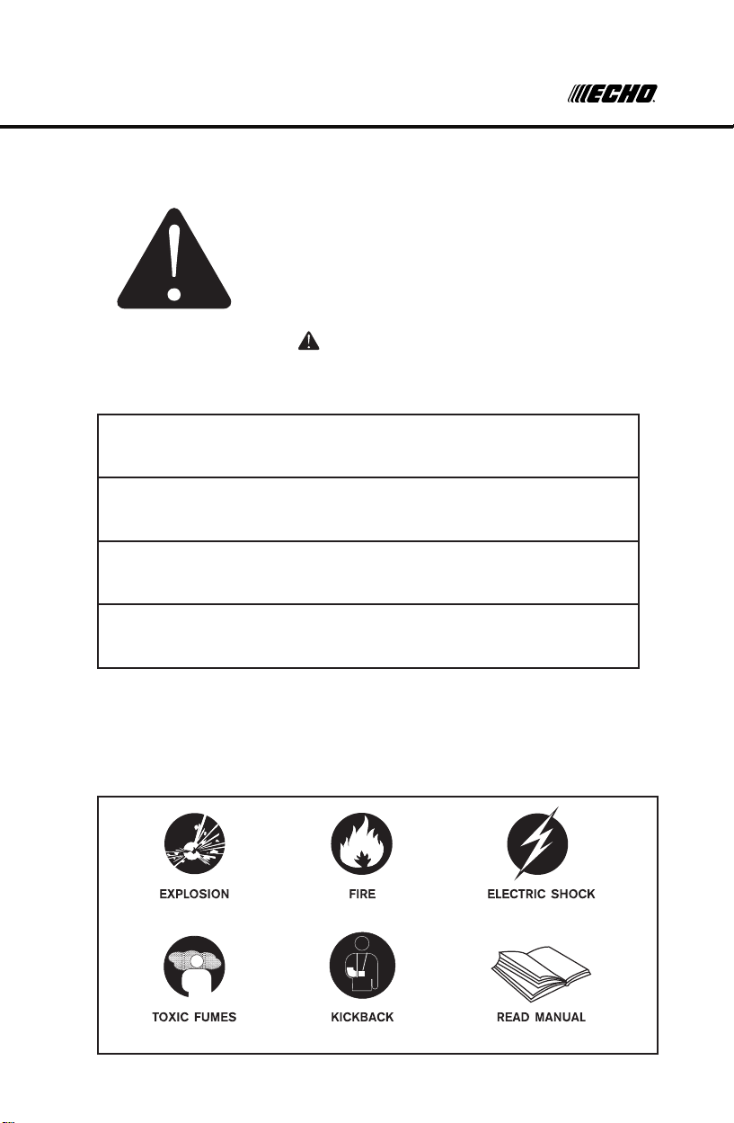
HAZARD SYMBOLS AND MEANINGS
5
Page 6
SAFETY
Read and understand this owner’s manual before operating your
generator. It will help you avoid accidents if you are familiar with your
generator’s safe operation procedures.
WARNING
Generator exhaust contains carbon monoxide, a
poisonous gas that can kill you.
You CANNOT smell or see this gas.
• Use the generator outdoors, away from open windows, vents, or
doors that could allow the carbon monoxide gas to come indoors.
Keep the generator at least 1 meter (3 feet) away from any
structure or building during use.
• NEVER use a generator indoors, including in homes, garages,
basements, crawl spaces, and other enclosed or partiallyenclosed areas, even with ventilation. Opening doors and
windows or using fans will not prevent carbon monoxide build-up
in the home.
• NEVER use a generator in enclosed or partially-enclosed
spaces. Generators can produce high levels of carbon monoxide
very quickly. When you use a portable generator, remember that
you cannot smell or see carbon monoxide. Even if you can’t smell
exhaust fumes, you may still be exposed to carbon monoxide.
• NEVER operate the generator in an explosive atmosphere, near
combustible materials or where ventilation is not sucient to carry
away exhaust fumes. Exhaust fumes can cause serious injury or
death.
• If you start to feel sick, dizzy, or weak while using a generator, get
to fresh air RIGHT AWAY. DO NOT DELAY. The carbon monoxide
from generators can rapidly lead to full incapacitation and death.
• If you experience serious symptoms, seek medical attention
immediately. Inform medical sta that carbon monoxide poisoning
is suspected. If you experienced symptoms while indoors, have
someone call the re department to determine when it is safe
tore-enter the building.
6
Page 7
SAFETY
WARNING
Fuel and vapors are extremely ammable and
explosive.
Fire or explosion can cause severe burns or death.
WHEN ADDING OR DRAINING FUEL
• Observe all safety regulations for the safe handling of fuel.
Handle fuel in safety containers. If the container does not have a
spout, use a funnel.
• Do not overll the fuel tank, leave room for the fuel to expand.
• Do not rell fuel tank while the engine is running. Before refueling
the generator, turn it o and let it cool down. Gasoline spilled on
hot engine parts could ignite.
• Fill the tank only on an area of bare ground. While fueling the
tank, keep heat, sparks and open ame away. Carefully clean up
any spilled fuel before starting engine.
• Always ll fuel tank in an area with plenty of ventilation to avoid
inhaling dangerous fumes.
• NEVER store fuel for your generator in the home. Gasoline,
propane, kerosene, and other ammable liquids should be stored
outside of living areas in properly-labeled, non-glass safety containers. Do not store them near a fuel-burning appliance, such
as a natural gas water heater in a garage. If the fuel is spilled or
the container is not sealed properly, invisible vapors from the fuel
can travel along the ground and can be ignited by the appliance’s
pilot light or by arcing from electric switches in the appliance.
7
Page 8
SAFETY
If the generator should malfunction, grounding provides a path of least
resistance for electric current to reduce the risk of electric shock.
DANGER
Improper grounding can result in a risk of
electrocution. Check with a qualied electrician for
your local requirements if you are in doubt as to
whether the unit is properly grounded.
This generator is equipped with a grounding terminal for added
protection. Using the ground path from the generator to an external
ground source as instructed in the section labeled “Grounding
Instructions” in the CONTROL FUNTION section of this manual
can be necessary. Please consult a qualied electrician for local
regulations.
The generator is a potential source of electrical shock if not kept dry.
Keep the generator dry and do not use in rain or wet conditions. To
protect from moisture, operate it on a dry surface under an open,
canopy-like structure. Dry your hands if wet before touching the
generator.
Plug appliances directly into the generator. Or, use a heavy duty,
outdoor-rated extension cord that is rated (in watts or amps) at least
equal to the sum of the connected appliance loads. Check that the
entire cord is free of cuts or tears and that the plug has all three
prongs,especially a grounding pin.
NEVER try to power the house wiring by plugging the generator into
a wall outlet, a practice known as “back feeding”. This is an
extremely dangerous practice that presents an electrocution risk to
utility workers and neighbors served by the same utility transformer.
It also bypasses some of the built-in household circuit protection
devices.
If you must connect the generator to the house wiring to power
appliances, have a qualied electrician install the appropriate
equipment in accordance with local electrical codes.
8
Page 9
SAFETY
IMPORTANT SAFETY INSTRUCTIONS
WARNING
To reduce the risk of injury, read this operator’s
manual completely before using.
When using this product, the following basic
precautions should always be followed.
• Do not enclose the generator or cover it. The generator may
become overheated if it is enclosed.
• If generator has been covered to protect it from the weather during
non use, be sure to remove it and keep it well away from the area
during generator use.
• Operate the generator on a level surface. It is not necessary to
prepare a special foundation for the generator. However, the
generator will vibrate on an irregular surface, so choose a level
place.
• If the generator is tilted or moved during operation, fuel may spill
and/or the generator may tip over, causing a hazardous situation.
Proper lubrication cannot be expected if the generator is operated
on a steep incline or slope. In such a case, piston seizure may
occur even if the oil is above the upper level.
• Pay attention to the wiring or extension cords from the generator
to the connected device. If the wire is under the generator or in
contact with vibrating part, it may break and possibly cause a re,
generator burnout, or electric shock hazard. Replace damaged or
worn cords immediately.
• Do not operate in rain, in wet or damp conditions, or with wet
hands. The operator may suer severe electric shock if the
generator is wet due to rain or snow. If wet, wipe and dry it well
before starting. Do not pour water directly over the generator, nor
wash it with water.
• Be extremely careful that all necessary electrical grounding
procedures are followed during each and every use. Failure to do
so can be fatal.
• DO NOT smoke while charging a battery. The battery emits
ammable hydrogen gas, which can explode if exposed to electric
arcing or open ame. Keep the area well ventilated and keep open
ames / sparks away when charging a battery.
• The engine becomes extremely hot during and for some time after
operation. Keep combustible materials well away from generator
area. Be very careful not to touch any parts of the hot engine
9
Page 10

SAFETY
especially the muer area or serious burns may result.
• Keep children and all bystanders at a safe distance from work area.
• It is absolutely essential that you know the safe and proper use of
the power tool or appliance that you intend to use. All operators
must read, understand and follow the tool / appliance owners
manual. Tool and appliance applications and limitations must be
understood. Follow all directions given on labels and warnings.
Keep all instruction manuals and literature in a safe place for future
reference.
• Use only “LISTED” extension cords. When a tool or appliance is
used outdoors, use only extension cords marked “For Outdoor Use”
Extension cords, when not in use should be stored in a dry and well
ventilated area.
• Always switch o generator’s AC circuit breaker and disconnect
tools or appliances when not in use, before servicing, adjusting, or
installing accessories and attachments.
• Make sure the engine is stopped before starting any maintenance,
servicing or repair.
NOTE: Make sure maintenance and repair of the generator are
performed by properly trained personnel only.
SA VE THESE INSTRUCTIONS
10
Page 11
DESCRIPTION
2 . DISCRIPTION
2 .1 Control panel
3. CONTROL FUNCTION
3.1 Switch knob
3.2 LED functions display(For electric start version)
① Engine switch \fuel valve “OFF”;
Ignition circuit is switched off. Fuel is switched off.
The engine will not run.
② Engine switch \fuel valve \ choke “ON”
Ignition circuit is switched on. Fuel is switched on. Choke is switched on.
The engine can be running.
③ Engine switch \fuel valve \ choke “CHOKE” ;
Ignition circuit is switched on. Fuel is switched on. Choke is switched off.
The engine can be start.
TIP: The choke is not required to start a warm engine.
;
ElectricRecoil
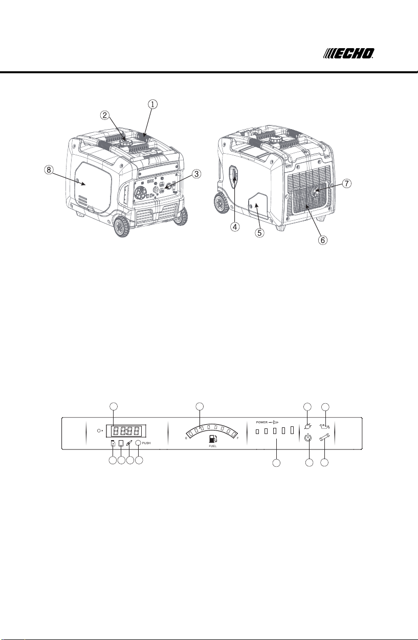
BREAKDOWN
1. Carrying handle
2. Fuel tank cap
3. Control panel
4. Recoil starter
5. Oil ller cap
6. Louver
7. Muer
8. Spark plug cover
LED FUNCTION DISPLAY (EGI-3600LN)
5
6
7
25%
50%
75%
100%
110%
1
4
3
2
11
10
9
1. Oil change indicator
2. Air cleaner maintenance indicator
3. Spark plug maintenance indicator
4. Switch button
5. Multi functional digital meter
6. Fuel level indicator
7. On-load indicator
8. Oil alert indicator
9. Inverter running indicator
10. Inverter alert indicator
11. Power display
8
11
Page 12

DESCRIPTION
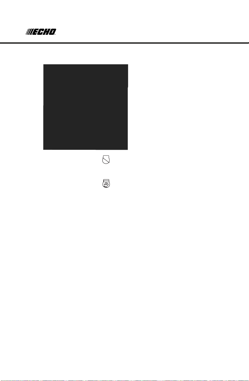
4
25%
50%
75%
100%
110%
240V
5 - Multi functional digital meter
Voltage-U000, Frequency-F00.0, Total working time-000.0(0.1h) ,
Working hours at one time-00.00 Switch the display by pushing - 4
1 - Red
Oil change indicator, rst time indicate after 50hrs, and then
indicate once every 100hrs. Every indicating lasts 1hr.
2 - Red
Air cleaner maintenance indicator, indicate once every 100hrs.
Every indicating lasts 1hr.
3 - Red
Spark plug maintenance indicator,indicate once every 100hrs.
Every indicating lasts 1hr.
6 - Fuel level indicator
A B C D E
Full-Green, all lights on Low
fuel level-lights turn orange
11 - Power display
Power lower than 25%, light A turns green. Power display Power
lower than 50%, light A&B turns green.
Power lower than 75% light A&B&C turns green.
Power lower than 100%, light A&B&C&D turns green.
Power higher than 100%,but lower than 110%, light A&B&C&D turns
green&red.
Power higher than 110%, light A&B&C&D&E turns red.
7 - Green On-load indicator light on green while the inverter is on-load.
8 - Red Oil alert light on while the oil is empty
9 - Green Inverter working indicator.
10 - Red Inverter alert indicator. Light is o while this light is constantly on
12
Page 13

CONTROL PANEL FUNCTION
CONTROL PANEL
1. AC reset
2. ECS(Engine Smart Control)
3. AC receptacle
4. Parallel function
5. Ground (earth) terminal
6. USB
7. DC receptacle
8. DC Protector
9. AC breaker
10. Switch knob
13
Page 14
CONTROL PANEL FUNCTION
3 IN 1 SWITCH KNOB
(1) Engine switch\fuel valve “OFF”;
Ignition circuit is switched o. Fuel is switched o.
The engine will not run.
(2) Engine switch\fuel valve “ON”;
Ignition circuit is switched on. Fuel is switched on. Choke is
switched on. The engine can be started.
OIL WARNING LIGHT (RED)
When the oil level falls below the lower level, the oil warning light (1)
comes on and then the engine stops automatically. Unless you change
the oil, the engine will not start again.
TIP: If the engine stalls or does not start, turn the engine switch to
“ON” and then pull the recoil starter. If the oil warning light ickers for a
few seconds, the engine oil level is insucient. Add oil and restart.
14
Page 15

CONTROL PANEL FUNCTION
OVERLOAD INDICATOR LIGHT (RED)
The overload indicator light (1) comes on when an overload of a
connected electrical device is detected, the inverter control unit
overheats, or the AC output voltage rises. Then, the AC protector will
trip, stopping power generation in order to protect the generator and
any connected electric devices. The AC pilot light (Green) will go o
and the overload indicator light (Red) will stay on, but the engine will
not stop running.
When the overload indicator light comes on and power generation
stops, proceed as follows:
1. Turn o any connected electric devices and stop the engine.
2. Reduce the total wattage of connected electric devices within the
rated output.
3. Check for blockages in the cooling air inlet and around the control
unit. If any blockages are found, remove them.
4. After checking, restart the engine.
TIP: The overload indicator light may come on for a few seconds at
rst when using electric devices that require a large starting current,
such as a compressor or a submergible pump. This is normal and
should not be treated as a malfunction.
AC POWER INDICATOR (GREEN)
The AC power indicator (1) comes on when the engine starts and
produces power.
15
Page 16

CONTROL PANEL FUNCTION
DC PROTECTOR
The DC protector turns to “OFF” (2) automatically when the electric
device connected to the generator is operated above rated ow. To
use this equipment again, turn on DC protector by pressing its button
to “ON” (1)
(1) “ON”
Outputting direct current.
(2) “OFF”
Not outputting direct current.
CAUTION
• Reduce the load of the connected electric device below the
specied rated output of the generator if the DC protector turns
o. If the DC protector turns o again, stop using the device
immediately and consult your local dealer.
ENGINE SMART CONTROL (ESC)
(1) “ON”
When the ESC switch is turned to “ON”, the
economy control unit controls the engine speed
according to the connected load. This results in
better fuel economy and reduced noise output.
(2) “OFF”
When the ESC switch is turned to“OFF”, the
engine runs at the rated
r/min(4500r/min) regardless of whether a load is connected or not.
TIP: The ESC must be turned to“OFF”when using electric devices
that require a large starting current, such as a compressor of a
submersible pump.
16
Page 17

CONTROL PANEL FUNCTION
FUEL TANK CAP
Remove the fuel tank cap by turning it counterclockwise.
GROUND (EARTH) TERMINAL
Ground (Earth) terminal (1) connects the earth line for the prevention
of an electric shock. All electrical tools and appliances operated from
this generator must be properly grounded by use of a third wire or
have cords that are “Double Insulated”
AIR INDEX
An Air Index Information hang tag/label is applied to engines certied
to an emission durability time period in accordance with the
requirements of the California Air Resources Board.
The bar graph is intended to provide you, our customer, the ability to
compare the emissions performance of available engines. The lower
the Air Index, the less pollution.
17
Page 18

CONTROL PANEL FUNCTION
GROUNDING INSTRUCTIONS
DANGER
Improper connection of the equipment grounding
conductor can result in a risk of electrocution.
Check with a qualied electrician if you are in doubt as to whether
the unit is properly grounded for your local regulations.
The ground terminal on the frame can be used to connect the
generator to a suitable ground source. The ground path should be
made with #8 size wire. Connect the grounding wire securely to the
ground terminal. Connect the other end of the wire securely to a
suitable ground source.
A metal underground water pipe in direct contact with the earth
for at least 10 feet can be used as a grounding source. If a pipe is
unavailable, an 8 foot length of pipe or rod may be used as the ground
source. The pipe should be 3/4” diameter or larger and the outer
surface must be noncorrosive. If a steel or iron rod is used it should
be at least 5/8” diameter and if a nonferrous rod is used it should be at
least 1/2” diameter and be listed as material for grounding. Drive the
rod or pipe to a depth of 8’. If a rock bottom is encountered less than
4 feet down, bury the rod or pipe in a trench. All electrical tools and
appliances operated from this generator, must be properly grounded
by use of a third wire or be “Double Insulated”.
It is recommended to:
1. Use electrical devices with 3 prong power cords.
2. Use an extension cord with a 3 hole receptacle and a 3 prong plug
at the opposite ends to ensure continuity of the ground protection
from the generator to appliance.
We strongly recommend that all applicable regulations relating to
grounding specications be checked and followed.
18
Page 19

PREPARATION
FUEL
DANGER
• Fuel is highly ammable and poisonous. Check
“SAFETY INFORMATION” carefully before lling.
• Do not overll the fuel tank, otherwise it may
overow when the fuel warms up and expands.
• After lling, make sure the fuel tank cap is tightened
securely.
GENERAL RECOMMENDATIONS
• Purchase gasoline in small quantities and store in clean, approved
containers.
• To minimize gum deposits in your fuel system and to insure easy
starting, do not use gasoline left over from the previous season.
• Do not add oil to the gasoline.
• Consider adding fuel stabilizer before running or starting the
generator.
Recommended fuel: Gasoline with octane rating of 87 or higher
Fuel tank capacity: 9L, 2.2 GAL
Remove the fuel tank cap and ll the fuel into the tank up to the
red level.
(1) Red line (2) Fuel level
NOTICE
• Immediately wipe o spilled fuel with a clean and dry cloth. Fuel
may deteriorate painted surfaces or plastic parts if left on them.
• Use only unleaded gasoline. The use of leaded gasoline will cause
severe damage to internal engine parts.
ENGINE OIL
Before checking or relling oil, be sure generator is located on stable
and level surface with engine stopped. This generator uses SAE
10W30 oil.
1. Turn the oil service knob to “OPEN” and remove the service door.
2. Remove oil dipstick and check the engine oil level.
3. If oil level is below the lower level line, rell with suitable oil to upper
level line. Do not screw in the oil dipstick when checking oil level.
4. Change oil if contaminated.
19
Page 20

PREPARATION
The generator has been shipped without engine oil. Do not start the engine till
fill with the sufficient engine oil.
1. Place the generator on a level surface.
2. Screw the oil service door knob to "OPEN" and remove the oil service door.
3. Screw-out the oil plug, then screw-in sealing plug into the pouring orifice,
and use the funnel to add the specified amount of oil.
4. Screw the oil plug, installed oil service door and keep the knob to "CLOSE".
4.2 Engine oil
Oil service door
Lubricating oil pipe
Oil plug
NOTICE
Always check the level of the engine oil prior to
starting the generator.
• Failure to do so could cause the engine to seize if the oil is low or
empty.
Recommended engine oil:
SAE SJ 10W-30
High Mark
Recommended engine oil grade:
API Service SE type or higher
Engine oil quantity: 0.5 L
Operating Range
Low Mark
NOTE: Recommended oil
may vary due to ambient air
temperature. see oil graphic
for more information.
-20 0-40 40 60 80 100 122
20
32°F
0°C
-10-30 -20-40 10 20 30 40 122
PRE-OPERATION CHECK
WARNING
• If any item in the Pre-operation check is not working properly, have
it inspected and repaired before operating the generator.
• The condition of a generator is the owner’s responsibility. Vital
components can start to deteriorate quickly and unexpectedly,
even if the generator remains unused for a period of time.
20
Page 21

PREPARATION
TIP: Pre-operation checks should be made each time the generator is
used.
Pre-operation check
Fuel (See page 19)
• Check fuel level in fuel tank.
• Refuel if necessary. Be careful not to overll!
Engine oil (See page 20)
• Check oil level and condition in engine.
• If necessary, add recommended oil to specied level or change oil.
• Check generator for oil leakage.
OPERATION
WARNING
• Never operate the engine in a closed area or it may cause
unconsciousness and death within a short time. Operate the
engine in a well ventilated area.
• Before starting the engine, do not connect any electric devices.
NOTICE
• The generator has been shipped without engine oil. Do not start
the engine till ll with the sucient engine oil.
• Do not tilt the generator when adding engine oil. This could result
in overlling and damage to the engine.
Operation of this equipment may create sparks that can start res
around dry vegetation. This unit may be equipped with a spark arrester
to prevent discharge of hot particles from the engine. The spark arrester
may be a standard or an optional part, depending on the engine type.
In some areas, it is illegal to operate an engine without a spark arrester.
Check local, state, and federal laws and regulations. A spark arrester is
available from authorized servicing dealers.
TIP: The generator can be used with the rated output load at standard
atmospheric conditions.
Standard Atmospheric Conditions:
Ambient temperature 25°, Barometric pressure 100kPa
Relative humidity 30%
The output of the generator varies due to changes in temperature,
altitude (lower air pressure at higher altitude) and humidity. The output
of the generator is reduced when the temperature, humidity, and the
altitude are higher than standard atmospheric conditions. Additionally,
the load must be reduced when using in a conned area, as generator
cooling is aected. We do not recommend using the generator in a
conned area, as adequate ventilation must be a priority.
21
Page 22

OPERATION
Handle
Press towards
the left
STARTING THE ENGINE
1. Turn the ESC switch to “OFF” (1).
2. Turn the air vent knob to “ON” (2).
3. Turn the 3 in 1 switch to “CHOKE” (3),
a. Ignition circuit is switched on.
b. Fuel is switched on.
c. Choke is switched on
TIP: The choke is not required to start a warm engine. Push the choke
knob to the position “ON”.
4. Use electric start or pull slowly on the
recoil starter until you feel slight
resistance, then pull it briskly.
TIP: Grasp the carrying handle rmly to prevent the
generator from falling over when pulling the recoil starter.
5. After the engine starts, warm up the engine until it doesn’t stop
when the choke knob is returned to the “ON” position (4).
CAUTION
Do not connect appliances with defective power cords and/or plugs.
Be sure appliances are not connected to generator when starting
up. Starting the generator with an appliance connected could result
in damage to the generator and/or appliances and personal injury.
TIP: When starting the engine, with the ESC “ON”, and there is no
load on the generator:
• In ambient temperature below 0°C (32°F), the engine will run at the
rated r/min (4500r/min) for 5 minutes to warm up the engine.
• In ambient temperature below 5°C (41°F), the engine will run at the
rated r/min (4500r/min) for 3 minutes to warm up the engine.
• The ESC unit operates normally after the above time period, while
the ESC is “ON”.
22
Page 23

OPERATION
NOTICE
This generator is thoroughly tested and adjusted in the factory. If
the generator does not produce the specied voltage, consult your
nearest authorized dealer.
1. Turn o the switch(es) of the electrical appliance(s) before
connecting to the generator.
2. Insert the plug(s) of the electrical appliance(s) into the receptacle.
• Be sure that the total wattage of all connected appliances does
not exceed the rated output of the generator.
3. Turn on the switch of the appliance.
STOPPING THE ENGINE
TIP: Turn o any electric devices.
1. Turn the ESC to “OFF” (1).
2. Disconnect any electric devices.
3. Turn the 3 in 1 switch to “OFF” ,
a. Ignition circuit is switched o.
b. Fuel is switched o.
23
Page 24

OPERATION
ALTERNATING CURRENT (AC) CONNECTION
WARNING
• Be sure any electric devices are turned o before plugging them in.
NOTICE
• Be sure all electric devices including the lines and plug
connections are in good condition before connection to the
generator.
• Be sure the total load is within the generator’s rated output.
• Be sure the receptacle load current is within receptacle rated
current.
• The generator (STATOR WINDING) is isolated from the AC
receptacle ground pin.
• Electrical devices that require a grounded receptacle pin
connection will not function if the receptacle ground pin is not
functional.
TIP: Make sure to ground the generator. When the electrical device is
grounded, the generator must also be grounded.
1. Start the engine.
2. Turn the ESC to “ON”.
3. Plug in to AC receptacle.
4. Make sure the AC pilot light is on.
5. Turn on any electric devices.
TIP: The ESC must be turned to “OFF” to increase engine speed
to rated rpm. If the generator is connected to multiple loads, please
remember to connect the one with the highest starting current rst and
connect the one with the lowest starting current last.
BATTERY CHARGING
TIP:
• The generator DC rated voltage is 12V.
• Start the engine rst, and then connect the generator to the battery
for charging.
• Before starting to charge the battery, make sure that the DC
protector is turned on.
1. Start the engine.
2. Connect the red battery charger lead to the positive (+) battery
terminal.
3. Connect the black battery charger lead to the negative (-) battery
terminal.
4. Turn the ESC “o” to start battery charging.
24
Page 25

OPERATION
NOTICE
• Be sure the ESC is turned o while charging the battery.
• Be sure to connect the red battery charger lead to the positive (+)
battery terminal ,and connect the black lead to the negative (-)
battery terminal. Do not reverse these positions.
• Connect the battery charger leads to the battery terminals securely so that they are not disconnected due to engine vibration
or other disturbances.
• Charge the battery in the correct procedure by following instructions in the owner’s manual for the battery.
• The DC protector turns o automatically if current above the rated
ows during battery charging. To restart charging the battery,
turn the DC protector on by pressing its button to “ON”. If the DC
protector turns o again, top charge the battery immediately and
consult our company authorized dealer.
TIP:
• Follow instructions in the owner’s manual for the battery to
determine the end of battery charging.
• Measure the specic gravity of electrolyte to determine if the battery
is fully charged. At full charge, the electrolyte specic gravity is
between 1.26 and 1.28.
• It is advisable to check the specic gravity of the electrolyte at least
once every hour to prevent overcharging the battery.
WARNING
• Never smoke or make and break connections at the battery while
charging. Sparks may ignite the battery gas.
• Battery electrolyte is poisonous and dangerous, causing severe
burns, etc. contains sulfuric (sulphuric) acid. Avoid contact with
skin, eyes or clothing.
• Antidote:
EXTERNAL: Flush with water.
INTERNAL: Drink large quantities of water or milk. Follow with
milk of magnesia, beaten egg or vegetable oil . Call physician
immediately.
EYES: Flush with water for 15 minutes and get prompt medical
attention.
• Batteries produce explosive gases. Keep sparks, ame,
cigarettes, etc., away. Ventilate when charging or using in closed
space. Always cover eyes when working near batteries.
• Keep out of reach of children.
25
Page 26
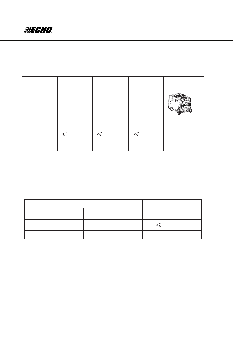
3kW
GENERATOR
OPERATION
APPLICATION RANGE
When using the generator, make sure the total load is within rated
output. Otherwise, damage to generator may occur.
AC
Power
Factor
1 0.8-0.95 0.4-0.75
(Eciency
Owner’s Manual
0.85)
Rated
continuous
3,000W
2,400W
1,020W
Rated
voltage 12V
output
power
TIP:
• Application wattage indicates when each device is used by itself.
• The simultaneous usage of AC and DC power is possible but total
wattage should not exceed the rated output.
EX:
Generator continuous output 3,000W
Frequency Power factor
AC 1.0 3,000W
DC --- 100W (12V/8.3A)
The overload indicator (1) comes on when total wattage exceeds the
application range. (See page 11 for more details)
26
Page 27

MAINTENACE
NOTICE
• Do not overload. The total load of all electrical appliances must
not exceed the supply range of the generator. Overloading will
damage the generator.
• When supplying precision equipment, electronic controllers,
PCs, Electronic computers, microcomputer based equipment or
battery chargers, keep the generator a sucient distance away to
prevent electrical interference from the engine. Also ensure that
electrical noise from the engine does not interfere with any other
electrical devices located near the generator.
• If the generator is to supply power to medical equipment, advice
should rst be obtained from the manufacturer or a medical
professional.
• Some electrical appliances or general-purpose electric motors
have high starting currents, and cannot therefore be used, even if
they lie within the supply ranges given in the above table. Consult
the equipment manufacturer for further advice.
The engine must be properly maintained to ensure its operation is
safe, economical, and free of issues.
Maintenance, replacement, or repair of emission control devices and
systems may be performed by any engine repair establishment or
individual, using parts that are ‘’certied’’ to EPA standards.
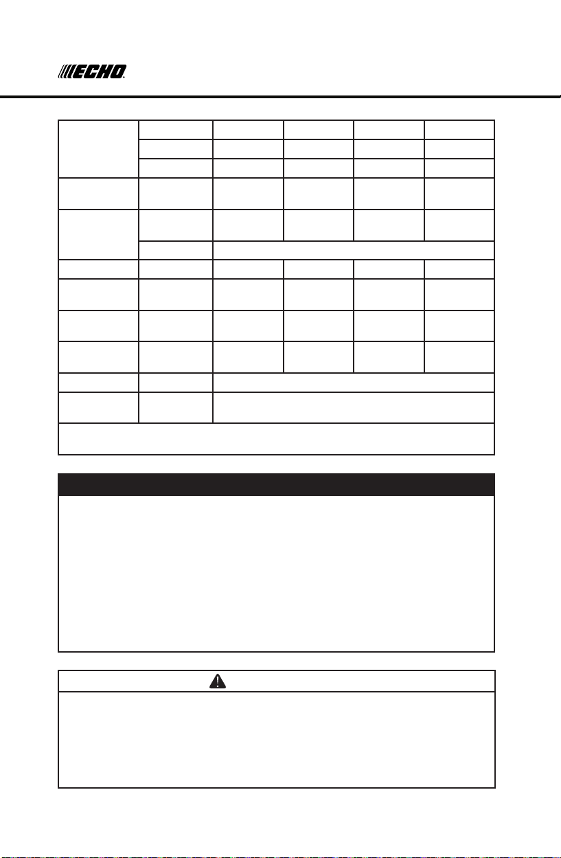
In order to keep your gasoline engine in good working condition, it
must be periodically serviced. The following maintenance schedule
and routine inspection procedures must be carefully followed:
Items Frequency Each time
Engine oil
Reduction gear
oil (if equipped)
Check-Rell X
Replace X X
Oil level check X
Replace X X
First month
or rst
20hrs of
operation
Thereafter,
every 3
months or
every 50hrs
of operation
Every year
or every
100hrs of
operation
27
Page 28
MAINTENANCE
Air lter
element
Deposit Cup
(if equipped)
Spark Plug
Spark arrester Clean X
Idling
(if equipped)*
Valve
clearance*
Fuel tank &
fuel lter*
Fuel line Check Every 2 years (change if necessary)
Cylinder
head, piston
* These items should be maintained and repaired by an authorized dealer unless
the owner has appropriate tools and is procient with mechanical maintenance.
Check X
Clean X
Replace X
Clean X
Check and
Adjust
Replace Every year or 250hrs of operation
Check-adjust X
Check-adjust X
Clean X
Clean up
carbon*
Every 250hrs
X
NOTICE
• If the gasoline engine frequently works under high temperature or
heavy load, change the oil every 25 hours.
• If the engine frequently work under dusty or other severe
circumstances, clean the air lter element every 10 hours; If
necessary, change the air lter element every 25 hours.
• The maintenance period and the exact time (hour), the one which
comes rst should govern.
• If you have missed the scheduled time to maintain your engine, do
it as soon as possible.
WARNING
• Stop the engine before servicing. Put the engine on a level surface
and remove the spark plug cap to prevent the engine from starting.
• Do not operate the engine in a poorly ventilated room or other
enclosed area. Be sure to keep good ventilation in working area.
The exhaust from the engine may contain poisonous CO, inhalation
can cause shock, unconsciousness and even death.
28
Page 29

MAINTENANCE
HIGH ALTITUDE REPLACEMENT KIT FOR EPAIII ENGINES
3000ft to 6000ft or 6000ft to 8000ft of elevation
• At high altitude, the standard carburetor air-fuel mixture will be too
rich. Performance will decrease and fuel consumption will increase. A
very rich mixture will also foul the spark plug and cause hard starting.
Operation at an altitude that diers from that at which this engine was
certied, for extended periods of time, may increase emissions.
• The fuel system on this Engine or Equipment may be inuenced
by operation at higher altitudes. Proper operation can be ensured
by installing an altitude kit when required. See the table below to
determine when an altitude kit is required. Operating this generator
without the proper altitude kit installed may increase the engine’s
emissions and decrease fuel economy and performance. Kits may
be obtained from any Dealer, and should be installed by a qualied
individual.
Equipment model* Fuel Altitude Range** Kit Part Number
0 – 3000 ft Not Required
Gasoline
3000 – 6000 ft Altitude kit 1#
6000 – 8000 ft Altitude kit 2#
* Engine, Generator Set, Pressure Washer, Walk-Behind Lawnmower,
Compressor, Pump, Tiller etc.
** Elevation above sea level.
* This high altitude jet is to be used at elevations above 3000 feet.
* At elevations above 8000 feet, the engine may experience decreased
performance, even with the high altitude kit.
If a carburetor is replaced, the proper high altitude kit jet will need to be
installed into the replacement carburetor.
WARNING
To prevent serious injury from re: Follow the kit procedures in
a well-ventilated area away from ignition sources. If the engine
is hot from use, shut the engine o and wait for it to cool before
proceeding.
NOTICE
The warranty may be void if necessary adjustments are not made
for high altitude use.
29
Page 30

MAINTENANCE
①
and the spark plug cap ② loot eht tresnI dna ,
SPARK PLUG INSPECTION
The spark plug is an important engine component which should be
checked periodically.
1. Remove the cover (1) and the spark plug cap (2). Insert the tool
through the hole from the outside of the cover.
Tool cover
①
2. Insert the handle (3) into the tool (4) and turn it counterclockwise to
remove the spark plug.
3. Check for discoloration and remove the carbon. The porcelain
insulator around the center electrode of spark plug should be a
medium-to-light tan color.
4. Check the spark plug type and gap.
Spark Plug:
TORCH F6RTC/F6TC
Spark Plug Gap: 0.6-0.8mm(0.024-0.03in)
TIP: The spark plug gap should be measured with a wire thickness
gauge and, If necessary, adjusted to specication.
5. Install the spark plug.
Spark Plug Torque: 28 N*m (1.25 kgf*m, 9 lbf*ft)
TIP: If a torque wrench is not available when installing a spark plug,
a good estimate of the correct torque is 1/4-1/2 turn past nger tight.
However, the spark plug should be tightened to the specied torque as
soon as possible.
6. Reinstall the spark plug cap and spark plug cover.
30
Page 31

MAINTENANCE
CARBURETOR ADJUSTMENT
The carburetor is a vital part of the engine. Adjusting should be left to
our company authorized dealer with the professional knowledge and
equipment to do so properly.
ENGINE OIL REPLACEMENT
WARNING
• Avoid draining the engine oil immediately after stopping the
engine. The oil is hot and should be handled with care to avoid
burns.
Avoid draining the engine oil immediately after stopping the engine. The
oil is hot and should be handled with care to avoid burns.
1. Place the generator on a level surface and warm up the engine for
several minutes. Stop the engine by turning the switch to “OFF”.
2. Remove the screws on the cover and then remove the cover.
3. Place an oil pan under the engine
4. Remove the oil ll cap and the oil drain bolt. Let oil drain completely.
5. Reinstall the oil drain bolt.
6. Add engine oil to the upper level. Reinstall the oil ll cap.
7. Wipe the cover clean, and wipe up any spilled oil.
8. Install the oil ller cap.
9. Install the cover and tighten the screws.
Recommended engine oil: SAE 10W30
Recommended engine oil grade: API Service SE type or higher
Engine oil quantity: 0.5L
NOTE: Recommended oil
may vary due to ambient air
temperature. see oil graphic
for more information.
-20 0-40 40 60 80 100 122
20
32°F
0°C
-10-30 -20-40 10 20 30 40 122
31
Page 32

MAINTENANCE
Be sure no foreign material enters the crankcase.
8. Install the oil filler cap.
9. Install the cover and tighten the screws.
6 .4 Air filter
1. Remove the screws ①, and then remove the cover ②.
2. Remove the screw ③ ③ and then remove the air filter case cover ④.
③
④
NOTICE
• Do not tilt the generator when adding engine oil. This could result
in overlling and damage to the engine.
NOTICE
• Be sure no foreign material enters the crankcase.
AIR FILTER
1. Remove the screws (1), and then remove the cover (2).
2. Remove the screw (3) and then remove the air lter case cover (4).
②
Foam element
④
3. Remove the foam element .
3. Remove the foam element (5).
1
4. Wash the foam element in solvent and dry it.
Foam element
5. Soak the foam element in oil and squeeze it
to remove any excess. The foam should be wet
but not dripping.
• Do not wring out the foam element when
squeezing it. This could cause it to tear.
NOTICE
6. Insert the foam element into the air lter case.
TIP: Be sure the foam element sealing surface
matches the air lter so there is no air leak.
32
Page 33

MAINTENANCE
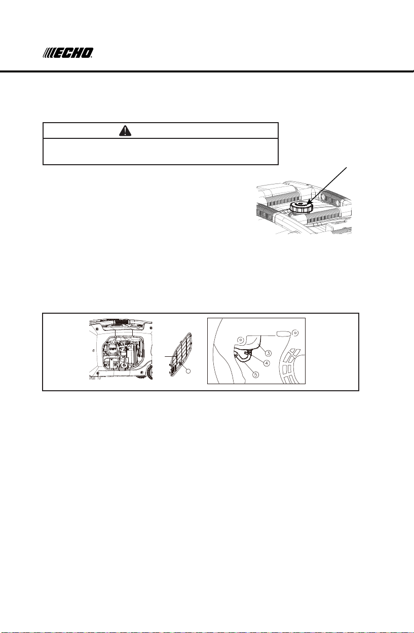
retser ra kraps dna neercs rel f fuM 5. 6
The engine and muffler will be very hot after the engine has been run.
Avoid touching the engine and muffler while they are still hot with any
part of your body or clothing during inspection or repair.
1. Remove the screws ①,
2. Remove the muffler cap , the muffler screen and spark arrester
3. Clean the carbon deposits on the muffler screen and spark arrester using a
wire brush.
②
③
④.
The engine should never run without the foam element;
excessive piston and cylinder wear may result.
7. Install the air lter case cover in its original position and tighten the
screw.
8. Install the cover and tighten the screws.
MUFFLER SCREEN AND SPARK ARRESTER
①
②
1. Remove the screws (1).
2. Remove the muer cap (2), the muer screen (3) and the spark
arrester (4).
3. Clean the carbon deposits on the silencer screen and the spark
arrester with a wire brush.
4. Check the muer screen and the spark arrester. Replace if
damaged.
5. Reinstall the spark arrester.
The spark arrester may be standard or an optional part, depending
on the engine type. In some areas, it is illegal to operate and engine
without a spark arrester. Check local, state, and federal laws and
regulations. A spark arrester is available from authorized servicing
dealers.
③
④
33
Page 34
MAINTENANCE
Fuel tank cap
Fuel tank cap
FUEL TANK FILTER
WARNING
• Never use the gasoline while smoking or in the
vicinity of an open ame.
1. Remove the fuel tank cap and lter.
2. Clean the lter.
3. Wipe the lter dry and reinstall it.
4. Install the fuel tank cap.
Be sure the fuel tank cap is tightened securely.
FUEL FILTER
1. Remove the screws (1), and then remove the cover (2), and drain
the fuel.
②
1
2. Hold and move up the clamp (4), then take o the hose (5) from
the tank.
3. Take out the fuel lter.
4. Clean the lter.
5. Dry the lter and put it back into tank.
6. Install the hose and clamp, then open the fuel valve to check
for leaks.
7. Install the cover and tighten the screws.
34
Page 35

STORAGE
Long term storage of your machine will require some preventive
procedures to guard against deterioration.
DRAIN THE FUEL
1. Turn the 3 in 1 switch to “OFF” (1) .
2. Remove the fuel tank cap and then remove the lter. Extract the
fuel from the fuel tank into an approved gasoline container. Then,
reinstall the fuel tank cap.
WARNING
• Fuel is highly ammable and poisonous. Check “SAFETY
INFORMATION” (page 6) carefully.
NOTICE
• Immediately wipe o spilled fuel with a clean, dry, and soft cloth as
fuel may deteriorate painted surfaces or plastic parts.
3. Start the engine (See Page 19) and leave it running until it stops.
The engine stops in approx. 20 minutes by running out of fuel.
TIP: Do not connect any electrical devices. (unloaded operation)
Duration of the running engine depends on the amount of the fuel left
in the tank.
4. Remove the screws, and then remove the cover.
5. Drain the fuel from the carburetor by loosening the drain screw on
the carburetor oat chamber.
6. Turn the 3 in 1 switch to “OFF”.
7. Tighten the drain screw.
8. Install the cover and tighten the screws.
35
Page 36

TROUBLESHOOTING
Engine
Perform the following steps to protect the cylinder, piston ring, etc.
from corrosion.
1. Remove the spark plug, pour about one tablespoon of SAE 10W-30
into the spark plug hole and reinstall the spark plug. Recoil start the
engine by turning over several times (with 4 in 1 switch knob o) to
coat the cylinder walls with oil.
2. Pull the recoil starter until you feel compression, then stop pulling.
(This prevents the cylinder and valves from rusting).
3. Clean exterior of the generator. Store the generator in a dry,
well-ventilated place, with the cover placed over it (cover sold
separately).
TROUBLESHOOTING
ENGINE WON’T START
1. Fuel systems
No fuel supplied to combustion chamber.
• No fuel in tank…Supply fuel.
• Fuel in tank….Fuel tank cap and fuel knob to “ON”
• Clogged fuel lter …. Clean fuel lter.
• Clogged carburetor…. Clean carburetor.
2. Engine oil system Insucient
• Oil level is low…. Add engine oil.
3. Electrical systems
• Put the 3 in 1 switch to “on” and pull the recoil starter … Poor
spark.
• Spark plug dirty with carbon or wet … Remove carbon or wipe
spark plug dry.
• Faulty ignition system … consult our company authorized dealer.
36
Page 37

SPECIFICATIONS
GENERATOR WON’T PRODUCE POWER
• Safety device (DC protector) to “OFF”, Press the DC protector to “ON”.
• The AC pilot light (Green) goes o …. Stop the engine, then restart.
SPECIFICATIONS
MODEL NUMBER EGi-3600LN
Type Silent inverter
Rated frequency (Hz) 50
Rated voltage (V) 240
Rated output power (kW) 1
Generator
Engine
Generator
set
Spark Arrester Equipped* Yes
* If a spark arrester is required it must meet the specications and performance
requirements of local, state, and federal laws and regulations. A spark arrester is
available from authorized servicing dealers.
Power factor 3.0
AC output quality ISO8528 G2
Charging voltage (DC) (V) 12
Charging current (DC) (A) 8.3
Overload protect (DC) Non-fuse protector
Engine R210-i
Engine type
Displacement (cc) 212
Fuel type Unleaded gasoline
Fuel tank capacity (L) 9.0
Oil capacity (L) 0.6
Spark plug model No. F6RTC
Valve clearance intake/exhaust 0.05 ~ 0.10
Starting mode Recoil Electric
Length×Width×Height (mm)
Net weight (kg)
Single cylinder,
4-Stroke, forced air
cooling, OHV
643×480×498
46
37
Page 38
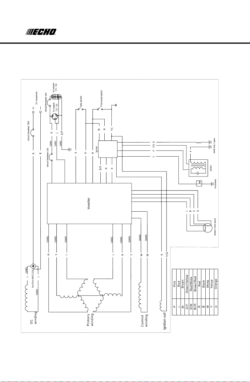
WIRING DIAGRAM
WIRING DIAGRAM
38
Page 39

WARRANTY
LIMITED WARRANTY STATEMENT
ECHO Incorporated warrants to the original retail purchaser that this ECHO®
brand outdoor product is free from defects in material and workmanship and
agrees to repair or replace at ECHO Incorporated’s discretion, any defective
product free of charge within these time periods from the date of purchase.
• 3 Year Consumer
• 90 Days Commercial
• 90 Days – For Rental Use
• 90 Days Accessories and Replacement Parts
This warranty extends to the original retail purchaser only and commences on
the date of the original retail purchase.
Any part of this product found, in the reasonable judgment of ECHO
Incorporated, to be defective in material or workmanship will be repaired or
replaced without charge for parts and labor by an authorized ECHO dealer.
Repair parts and accessories replaced under this warranty are warranted only
for the balance of the original warranty period.
The product, including any defective part, must be returned to an authorized
ECHO dealer within the warranty period. The expense of delivering the
product to the dealer for warranty work and the expense of returning it back
to the owner after repair or replacement will be paid by the owner. ECHO
Incorporated’s responsibility in respect to claims is limited to making the
required repairs or replacements and no claim of breach of warranty shall
be cause for cancellation or rescission of the contract of sale of any ECHO
brand outdoor product. Proof of purchase will be required by the dealer to
substantiate any warranty claim. All warranty work must be performed by an
authorized ECHO dealer.
This warranty does not cover any product that has been subject to misuse,
neglect, negligence, or accident, or that has been operated in any way
contrary to the operating instructions as specied in this Operator’
This warranty does not apply to any damage to the product that is the result
of improper maintenance or to any product that has been altered or modied.
The warranty does not extend to repairs made necessary by normal wear
or by the use of parts or accessories which are either incompatible with
the ECHO brand outdoor product, or that adversely aect its operation,
performance, or durability. In addition, this warranty does not cover wear to
normal items such as, but not limited to:
A. Tune-ups – Air lters, gas lters, carburetors, spark plugs, lters, oil
changes
B. Wear items – Recoil Starter Rope, Motor Brushes, Alternator Brushes,
Cotter Pins, Wheels
C. IMPORTANT: Some components not covered under this warranty
may still be covered by a separate warranty issued by the engine
s Manual.
39
Page 40

WARRANTY
manufacturer. Please see the Engine Manufacturer Warranty (if any)
supplied with this product for further details.
ECHO Incorporated reserves the right to change or improve the design of
this product without assuming any obligation to modify any product previously
manufactured.
ALL IMPLIED WARRANTIES ARE LIMITED IN DURATION TO THE STATED
WARRANTY PERIOD. ACCORDINGLY, ANY SUCH IMPLIED WARRANTIES
INCLUDING MERCHANTABILITY, FITNESS FOR A PARTICULAR
PURPOSE, OR OTHERWISE, ARE DISCLAIMED IN THEIR ENTIRETY
AFTER THE EXPIRATION OF THE APPROPRIATE THREE-YEAR OR
90 DAY WARRANTY PERIOD. ECHO INCORPORATED’S OBLIGATION
UNDER THIS WARRANTY IS STRICTLY AND EXCLUSIVELY LIMITED TO
THE REPAIR OR REPLACEMENT OF DEFECTIVE PARTS AND ECHO
INCORPORA TED DOES NOT ASSUME OR AUTHORIZE ANYONE TO
ASSUME FOR THEM ANY OTHER OBLIGATION. SOME STATES DO
NOT ALLOW LIMITATIONS ON HOW LONG AN IMPLIED WARRANTY
LASTS, SO THE ABOVE LIMITATION MAY NOT APPLY TO YOU. ECHO
INCORPORATED ASSUMES NO RESPONSIBILITY FOR INCIDENTAL,
CONSEQUENTIAL, OR OTHER DAMAGES INCLUDING, BUT NOT LIMITED
TO, EXPENSE OF RETURNING THE PRODUCT TO AN AUTHORIZED
DEALER FOR ECHO BRAND OUTDOOR PRODUCTS AND EXPENSE OF
DELIVERING IT BACK TO THE OWNER, MECHANIC’S TRAVEL TIME,
TELEPHONE OR TELEGRAM CHARGES, RENTAL OF A LIKE PRODUCT
DURING THE TIME WARRANTY SERVICE IS BEING PERFORMED,
TRAVEL, LOSS OR DAMAGE TO PERSONAL PROPERTY, LOSS OF
REVENUE, LOSS OF USE OF THE PRODUCT, LOSS OF TIME, OR
INCONVENIENCE. SOME STATES DO NOT ALLOW THE EXCLUSION OR
LIMITATION OF INCIDENTAL OR CONSEQUENTIAL DAMAGES, SO THE
ABOVE LIMITATION OR EXCLUSION MAY NOT APPLY TO YOU.
This warranty gives you specic legal rights, and you may also have other
rights which vary from state to state.
This warranty applies to ECHO brand Generators manufactured by or for
ECHO Incorporated and sold in the United States and Canada.
To locate your nearest authorized ECHO dealer, visit www.echo-usa.com or
dial 1-800-432-ECHO (3246).
ECHO Incorporated
400 Oakwood Rd. Lake Zurich, IL 60047
1-800-432-ECHO (3246)
www.echo-usa.com
40
Page 41

CARB AND EPA WARRANTY
CALIFORNIA AND FEDERAL EXHAUST AND EVAPORATIVE
EMISSIONS CONTROL WARRANTY STATEMENT
YOUR WARRANTY RIGHTS AND OBLIGATIONS
The California Air Resources Board, the United States Environmental
Protection Agency and Chongqing Rato Technology Co., Ltd. (Rato),
are pleased to explain the exhaust and evaporative emissions
(“emissions”) control system warranty on your 2019/2020 small o-
road engine/equipment.
In California, new equipment that use small o-road engines must be
designed, built, and equipped to meet the State’s stringent anti-smog
standards. Rato must warrant the emissions control system on your
small o-road engine/equipment for the period listed below provided
there has been no abuse, neglect or improper maintenance of your
small o-road engine/equipment leading to the failure of the emissions
control system.
Your emissions control system may include parts such as the
carburetor or fuel-injection system, the ignition system, catalytic
converter, fuel tanks, fuel lines (for liquid fuel and fuel vapors),
fuel caps, valves, canisters, lters, clamps and other associated
components. Also included may be hoses, belts, connectors, and
other emission-related assemblies.
Where a warrantable condition exists, Rato will repair your small o-
road engine/equipment at no cost to you including diagnosis, parts
and labor.
MANUFACTURER’S WARRANTY COVERAGE
The exhaust and evaporative emissions control system on your
small o-road engine/equipment is warranted for two years. If any
emissions-related part on your small o-road engine/equipment is
defective, the part will be repaired or replaced by Rato.
OWNER’S WARRANTY RESPONSIBILITIES
As the small o-road engine/equipment owner, you are responsible
for performance of the required maintenance listed in your owner’s
manual. Rato recommends that you retain all receipts covering
41
Page 42

maintenance on your small o-road engine/equipment, but Rato
cannot deny warranty coverage solely for the lack of receipts or for
your failure to ensure the performance of all scheduled maintenance.
As the small o-road engine/equipment owner, you should however
be aware that Rato may deny your warranty coverage if your small
o-road engine/equipment or a part has failed due to abuse, neglect,
or improper maintenance or unapproved modications.
You are responsible for presenting your small o-road engine/
equipment to a Rato distribution center or service center as soon
as the problem exists. The warranty repairs shall be completed in a
reasonable amount of time, not to exceed 30 days.
If you have questions regarding your warranty coverage, you can
email us at echo-usa.custhelp.com/app/ask or contact ECHO
Incorporated at 1-800-432-ECHO (3246), web site information is
available at WWW.ECHO-USA.COM.
DEFECTS WARRANTY REQUIREMENTS
A. The warranty period begins on the date the small o-road engine/
equipment is delivered to an ultimate purchaser.
B. General Emissions Warranty Coverage. Rato warrants to the
ultimate purchaser and each subsequent owner that the engine or
equipment is: Designed, built, and equipped so as to conform with
all applicable regulations adopted by the Air Resources Board;
and Free from defects in materials and workmanship that causes
the failure of a warranted part for a period of two years.
C. The warranty on emission-related parts will be interpreted as
follows:
1. Any warranted part that is not scheduled for replacement
as required maintenance in the written instructions must be
warranted for the warranty period dened in Subsection (b)(2).
If any such part fails during the period of warranty coverage, it
must be repaired or replaced by Rato according to Subsection
(4) below. Any such part repaired or replaced under the warranty
must be warranted for the remaining warranty period.
2. Any warranted part that is scheduled only for regular inspection
in the written instructions must be warranted for the warranty
period dened in Subsection (b)(2). A statement in such written
instructions to the eect of “repair or replace as necessary” shall
42
Page 43

advise owners of the warranty coverage for emissions related
parts. Replacement within the warranty period is covered by the
warranty and will not reduce the period of warranty coverage. Any
such part repaired or replaced under warranty must be warranted
for the remaining warranty period.
3. Any warranted part that is scheduled for replacement as required
maintenance in the written instructions must be warranted for the
period of time prior to the rst scheduled replacement point for
that part. If the part fails prior to the rst scheduled replacement,
the part must be repaired or replaced by Rato according to
Subsection (4) below. Any such part repaired or replaced under
warranty must be warranted for the remainder of the period prior
to the rst scheduled replacement point for the part.
4. Repair or replacement of any warranted part under the warranty
provisions must be performed at no charge to the owner at a
warranty station.
5. Notwithstanding the provisions of Subsection (4) above, warranty
services or repairs must be provided at distribution centers that
are franchised to service the subject engine/equipment.
6. The owner must not be charged for diagnostic labor that leads
to the determination that a warranted part is in fact defective,
provided that such diagnostic work is performed at a warranty
station.
7. Rato is liable for damages to other engine/equipment components
proximately caused by a failure under warranty of any warranted
part.
8. Throughout the emissions control system’s warranty period set
out in subsection (b)(2), Rato must maintain a supply of warranted
parts sucient to meet the expected demand for such parts and
must obtain additional parts if that supply is exhausted.
9. Manufacturer-approved replacement parts that do not increase
the exhaust or evaporative emissions of the engine or emissions
control system must be used in the performance of any warranty
maintenance or repairs and must be provided without charge to
the owner. Such use will not reduce the warranty obligations of
Rato.
10. Add-on or modied parts that are not exempted by the Air
Resources Board may not be used. The use of any non-exempted
add-on or modied parts will be grounds for disallowing a warranty
claim. Rato will not be liable to warrant failures of warranted parts
caused by the use of a non-exempted add-on or modied part.
11. Rato issuing the warranty shall provide any documents that
43
Page 44

describe that warranty procedures or policies within ve working
days of request by the Executive Ocer.
D - Emission Warranty Parts List for Exhaust
1. Fuel Metering System
• Carburetor and internal parts (and/or pressure regulator or fuel
injection system).
• Air/fuel ratio feedback and control system.
• Cold start enrichment system.
2. Air Induction System
• Controlled hot air intake system.
• Intake manifold.
• Air lter.
3. Ignition System
• Spark Plugs.
• Magneto or electronic ignition system.
• Spark advance/retard system.
4. Exhaust Gas Recirculation (EGR) System
• EGR valve body, and carburetor spacer if applicable.
• EGR rate feedback and control system.
5. Air Injection System
• Air pump or pulse valve.
• Valves aecting distribution of ow.
• Distribution manifold.
6. Catalyst or Thermal Reactor System
• Catalytic converter.
• Thermal reactor.
• Exhaust manifold.
7. Particulate Controls
• Traps, lters, precipitators, and any other device used to
capture particulate emissions.
8. Miscellaneous Items Used in Above Systems
• Electronic controls.
• Vacuum, temperature, and time sensitive valves and switches.
• Hoses, belts, connectors, and assemblies.
E - Emission Warranty Parts List for Evap
1. Fuel Tank
2. Fuel Cap
3. Fuel Lines (for liquid fuel and fuel vapors)
44
Page 45

4. Fuel Line Fittings
5. Clamps*
6. Pressure Relief Valves*
7. Control Valves*
8. Control Solenoids*
9. Electronic Controls*
10. Vacuum Control Diaphragms*
11. Control Cables*
12. Control Linkages*
13. Purge Valves*
14. Gaskets*
15. Liquid/Vapor Separator
16. Carbon Canister
17. Canister Mounting Brackets
18. Carburetor Purge Port Connector
*Note: As they relate to the evaporative emission control system.
Rato will furnish with each new small o-road engine/equipment
written instructions for the maintenance and use of the engine/
equipment by the owner.
45
Page 46

IF YOU NEED ASSISTANCE WITH THE ASSEMBLY OR OPERATION
OF THIS GENERATOR, PLEASE CONTACT US AT:
ECHO Incorporated
400 Oakwood Road
Lake Zurich, IL 60047
1-800-432-3246
www.echo-usa.com
E-mail: echo-usa.custhelp.com/app/ask
 Loading...