

Page 1
OPERATOR’S MANUAL
ENGINE DRILL
EDR-210
WARNING
READ INSTRUCTIONS CAREFULLY AND FOLLOW RULES FOR
SAFE OPERATION.
FAILURE TO DO SO COULD RESULT IN SERIOUS INJURY.
ECHO POWER EQUIPMENT(CANADA)
501 Newbold Street, London, Ontario Canada N6E 1K4
X750-004 72 3
X750409-3303
Printed in Japan 0906Ap 0389 ES
Page 2

This spark ignition system complies with Canadian ICES-002.
Copyright © 2002 All Rights Reserved.
Page 3
INTRODUCTION
ECHO Engine Drill EDR-210 is a lightweight, high
performance, two-stroke engined unit designed for
drilling.
This Manual provides the information necessary
for operation and maintenance.
SAFETY AND SPECIAL INFORMATION
WARNING
IMPROPER USE OR CARE OF THIS UNIT, OR
FAILURE TO WEAR PROPER PROTECTION
CAN RESULT IN SERIOUS INJURY. READ
AND UNDERSTAND THE RULES FOR SAFE
OPERATION AND ALL INSTRUCTIONS IN
THIS MANUAL.
DANGER
The safety alert symbol accompanied by the
word “DANGER” calls attention to an act or
condition which WILL lead to serious
personal injury or death if not avoided.
WARNING
The safety alert symbol accompanied by the
word “WARNING” calls attention to an act or
condition which CAN lead to serious
personal injury or death if not avoided.
NOTE
This enclosed message provides tips for use,
care and maintenance of the unit.
IMPORTANT
The enclosed message provides information
necessary for the protection of the unit.
CIRCLE AND SLASH SYMBOL
This symbol means the specific action
shown is prohibited. Ignoring these
prohibitions can result in serious or
fatal injury.
CAUTION
The safety alert symbol accompanied by the
word “CAUTION” calls attention to an act or
condition which may lead to minor or
moderate personal injury if not avoided.
Throughout this manual and on the product itself,
you will find safety alters and helpful, information
messages preceded by symbols or key words.
The following is an explanation of those symbols
and key words and what they mean to you.
CONTENTS
Introduction ........................................................................................................................................... 1
Safety and Special Information ............................................................................................................. 1
Safety .................................................................................................................................................... 2
Operating Techniques ........................................................................................................................... 5
Description ............................................................................................................................................ 6
Assembling ............................................................................................................................................ 7
Operation .............................................................................................................................................. 7
Maintenance and Care .......................................................................................................................... 11
Trouble shooting.................................................................................................................................... 12
Maintenance .......................................................................................................................................... 13
Storage .................................................................................................................................................. 15
Specifications ........................................................................................................................................ 16
Specifications, descriptions and illustrative material in this literature are as accurate as known at the time
of publication, but are subject to change without notice. Illustrations may include optional equipment and
accessories, and may not include all standard equipment.
1
Page 4
SAFETY
WARNING
ENGINE DRILL USERS RISK INJURY TO
THEMSELVES AND OTHERS IF THE ENGINE
DRILL IS USED IMPROPERLY, AND/OR
SAFETY PRECAUTIONS ARE NOT
FOLLOWED. PROPER CLOTHING AND
SAFETY GEAR MUST BE WORN WHEN
OPERATING ENGINE DRILL.
OPERATOR SAFETY
• Read this Engine drill Operator’s Manual
carefully. Be sure you understand how to
operate this unit properly before you use it.
• Be familiar with all the controls and the proper
use of the machine.
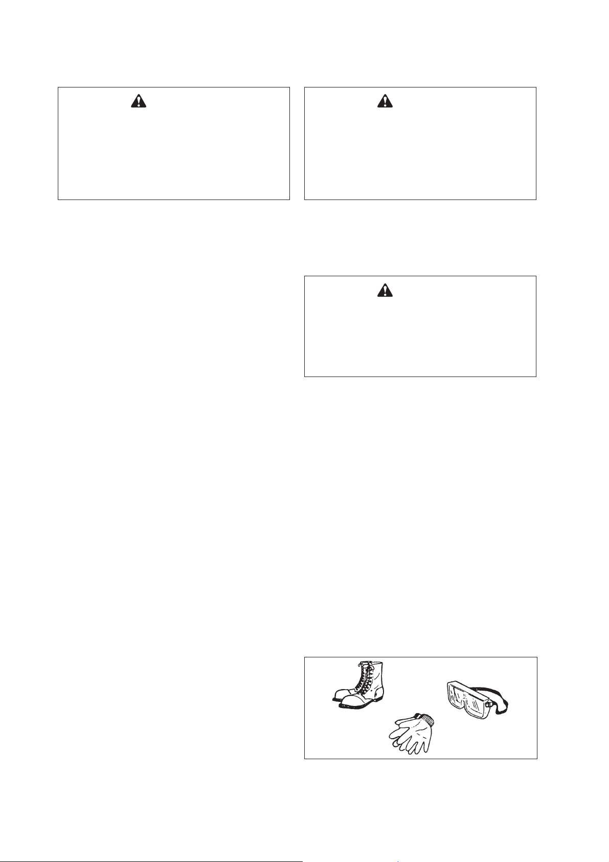
• Wear proper clothing to protect legs and other
exposed parts of your body.
• Wear non-skid sole shoes. Do not wear opentoed shoes or operate unit while bare footed.
• Wear eye and hearing protection devices.
• Use caution when handling fuel. Put the caps
back tightly on both the fuel can and the
engine drill fuel tank.
Move at least 3 m from the refueling point and
be sure there is no leakage of fuel from the fuel
tank cap or the fuel system before starting the
engine.
• Operate this gasoline powered engine
equipment in a well-ventilated area only.
WARNING
ALWAYS STOP THE ENGINE WHEN A DRILL
JAM OCCURS. DO NOT ATTEMPT TO
REMOVE AN OBJECT CAUSING A DRILL
JAM IF THE ENGINE IS RUNNING. PHYSICAL
INJURY CAN OCCUR IF A DRILL JAM IS
REMOVED AND THE DRILLS START
MOVING.
• Do all drilling at full throttle speed. Drilling at
less at than full speed can damage the clutch
by allowing it to slip.
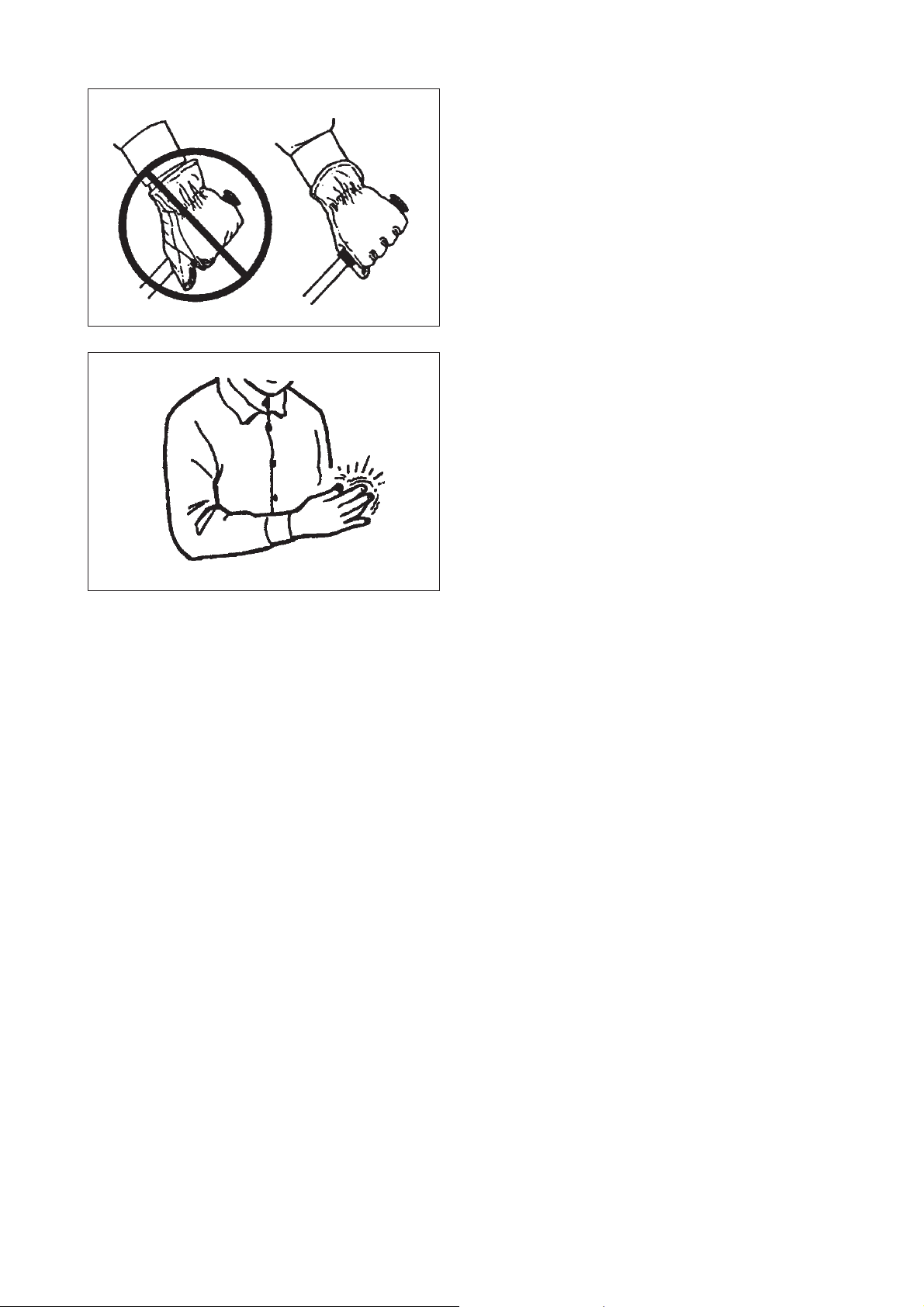
WARNING
USE A FIRM GRIP WITH THUMBS AND
FINGERS ENCIRCLING THE HANDLES. A
FIRM GRIP WILL HELP YOU KEEP
CONTROL OF THE ENGINE DRILL. NEVER
OPERATE THE ENGINE DRILL ONLY ONE
HAND OR BODILY INJURY CAN OCCUR.
• Always carry the engine drill with the engine
stopped and the HOT muffler away from your
body.
PROTECTIVE EQUIPMENT
• Always wear eye protection goggles that meet
ANSI Z87.1 standards.
• Wear hearing protection.
ECHO recommends that hearing protection be
worn at all times.
• Start the unit on the ground with the throttle set
at idle. Do not start if the drills are obstructed
by the ground or any other object.
• Never allow children to use the machine.
• Do not allow anyone to hold the material you
are drilling.
• Keep a firm grip on the engine drill with both
hands, one hand on the front handle, the other
hand on the rear handle.
• Dress properly! Do not wear loose clothing or
jewellery, they can be caught in moving parts.
Use of sturdy gloves, non-skid footwear, and
safety glasses is recommended.
• While operating the machine always be sure of
a secure position.
2
Page 5
• Wear non-slip, heavy-duty work gloves to
improve your grip on the engine drill handles.
The gloves also help reduce the transmission
of machine vibrations to your hands.
WARNING
PRECAUTION AGAINST VIBRATION
AND COLD
PROTECTING OTHERS
Spectators, children, fellow workers and animals
must be warned to come no nearer than 4.6 m
while the engine drill is in use.
People working in the area near you should wear
the same protective equipment as the operator.
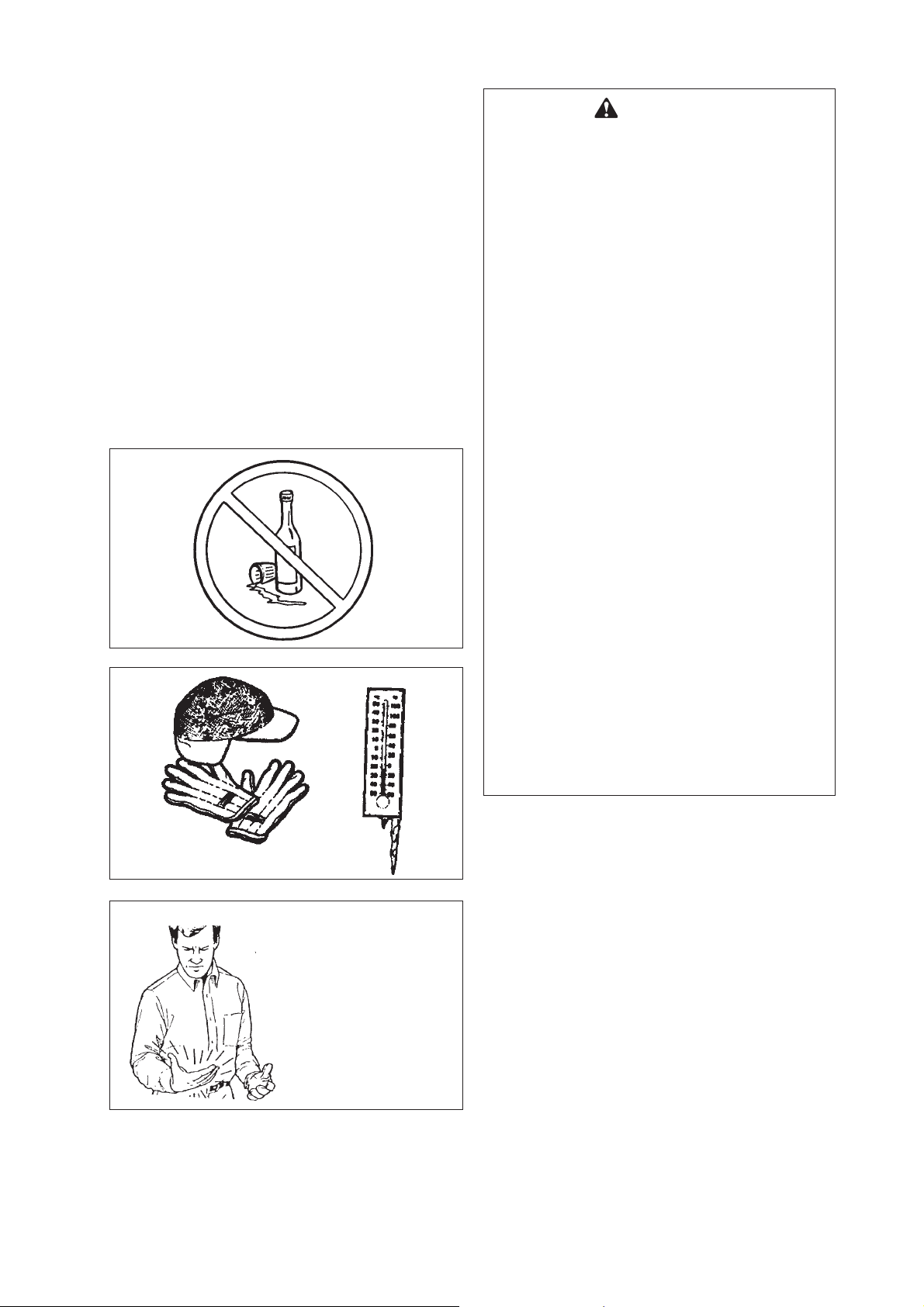
PHYSICAL CONDITION
Your judgement and dexterity may be impaired if
you are ill or have taken alcohol or other
substances known to affect the way you would
normally function.
IT IS BELIEVED THAT A CONDITION
CALLED RAYNAUD’S PHENOMENON,
WHICH AFFECTS THE FINGERS OF
CERTAIN INDIVIDUALS MAY BE BROUGHT
ABOUT BY EXPOSURE TO VIBRATION AND
COLD. EXPOSURE TO VIBRATION AND
COLD MAY CAUSE TINGLING AND
BURNING SENSATIONS FOLLOWED BY
LOSS OF COLOR AND NUMBNESS IN THE
FINGERS. THE FOLLOWING PRECAUTIONS
ARE STRONGLY RECOMMENDED BECAUSE
THE MINIMUM EXPOSURE WHICH MIGHT
TRIGGER THE AILMENT IS UNKNOWN.
• KEEP YOUR BODY WARM, ESPECIALLY
THE HEAD, NECK, FEET, ANKLES, HANDS
AND WRISTS.
• MAINTAIN GOOD BLOOD CIRCULATION
BY PERFORMING VIGOROUS ARM
EXERCISES DURING FREQUENT WORK
BREAKS AND ALSO BY NOT SMOKING.
• LIMIT THE HOURS OF OPERATION. TRY
TO FILL EACH DAY WITH JOBS WHERE
OPERATING THE ENGINE DRILL OR
OTHER HAND-HELD POWER EQUIPMENT
IS NOT REQUIRED.
Painful or numb fingers?
See your doctor
• IF YOU EXPERIENCE DISCOMFORT,
REDNESS AND SWELLING OF THE
FINGERS FOLLOWED BY WHITENING AND
LOSS OF FEELING, CONSULT YOUR
PHYSICIAN BEFORE FURTHER EXPOSING
YOURSELF TO COLD AND VIBRATION.
3
Page 6
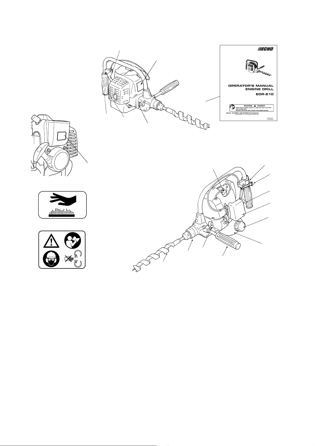
Repetitive Stress Injuries
It is believed that over-using the muscles and
tendons of the fingers, hands, arms and shoulders
may cause soreness, swelling, numbness,
weakness and extreme pain in those areas.
Certain repetitive hand activities may put you at a
high risk for developing a Repetitive Stress Injury
(RSI). An extreme RSI condition is Carpal Tunnel
Syndrome (CTS), which could occur when your
wrist swells and squeezes a vital nerve that runs
through the area. Some believe that prolonged
exposure to vibration may contribute to CTS. CTS
can cause severe pain for months or even years.
To reduce the risk of RSI/CTS, do the following:
• Avoid using your wrist in a bent, extended or
twisted position. Instead try to maintain a
straight wrist position. Also, when grasping,
use your whole hand, not just the thumb and
index finger.
• Take periodic breaks to minimize repetition
and rest your hands.
• Reduce the speed and force with which you do
the repetitive movement.
• Do exercise to strengthen the hand and arm
muscles.
• See a doctor if you feel tingling, numbness or
pain in the fingers, hands, wrists or arms.
The sooner RSI/CTS is diagnosed, the more
likely permanent nerve and muscle damage
can be prevented.
4
Page 7

OPERATING TECHNIQUES
• When starting to drill, run the engine at full
throttle.
WARNING
BEFORE DRILLING, BE SURE TO READ AND
UNDERSTAND THE ENTIRE OPERATOR’S
MANUAL TO AVOID THE CHANCE OF
SERIOUS INJURY.
• Do not force the drills and only move as
quickly as the drills will allow.
• Stop the engine and disconnect from ignition
cable before: - cleaning or when clearing a
blockage; checking, maintenance or working
on the machine.
• Handle fuel with care; it is highly flammable.
Never add fuel to a machine with a running or
hot engine.
• Do not attempt to repair the machine unless
you are qualified to do so.
• When transporting or storing the machine
always remove the drill bit.
• To reduce fire hazard keep engine and silencer
free of debris, leaves or excessive grease.
• Handle drill with care, contacting with drills
may cause injury.
• Do not operate the machine with a damaged or
excessively worn drill bit.
• Always ensure all handles and guards are
fitted when using the machine. Never attempt
to use an incomplete machine or one fitted with
an unauthorized modification.
5
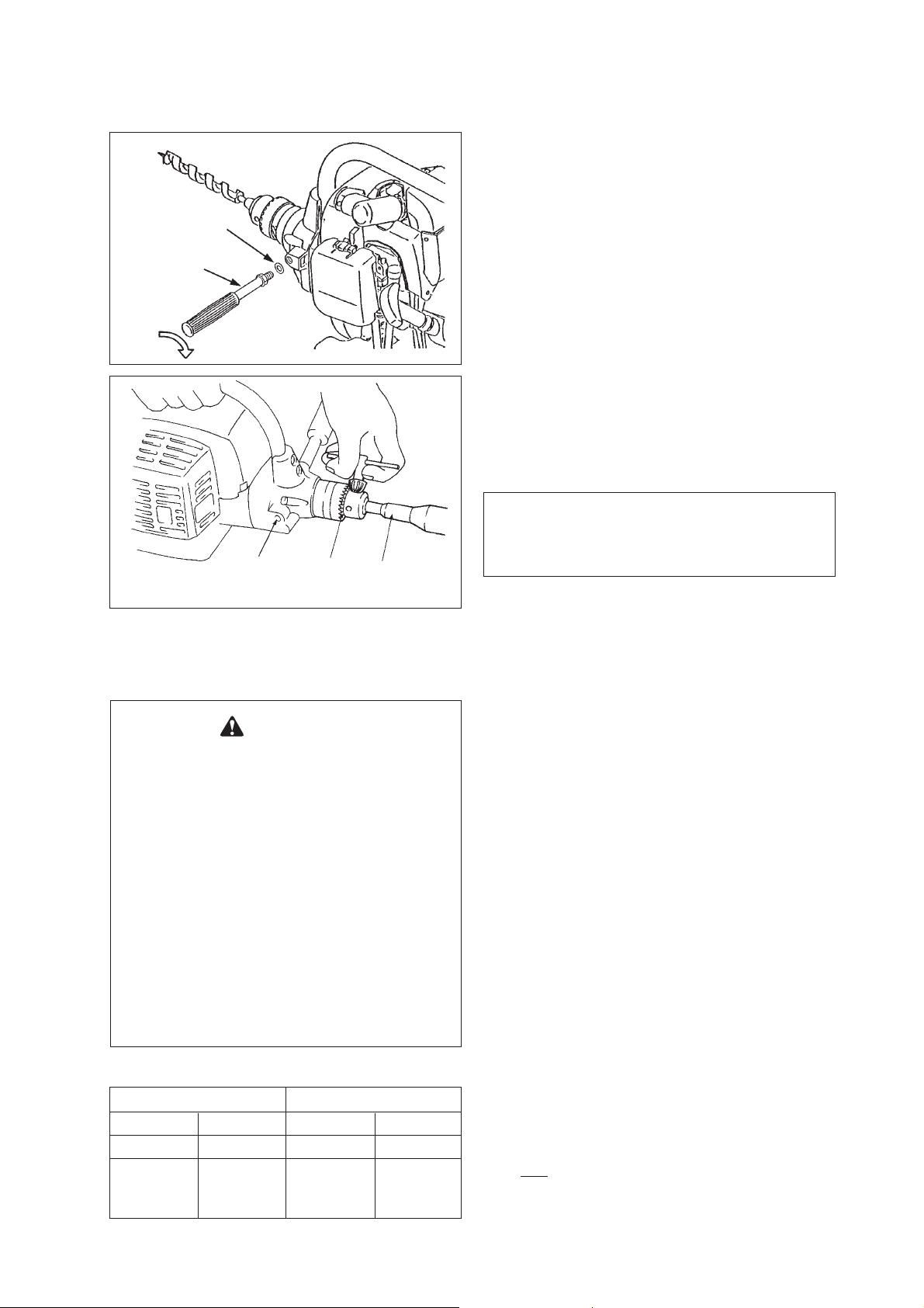
Page 8
DESCRIPTION
2
Part Number 890317-05560
Part Number X505-002570
Part Number X505-002310
Part Number X505-002570
3
4
Part Number X505-002310
1
15
7
6
8
5
14
13
12
11
10
9
* If a decal cannot be read, a new one can be
ordered from your ECHO dealer.
1. Operator’s manual - Included with unit. Read
before operation and keep for future reference
to learn proper, safe operating techniques.
2. Throttle trigger - Device activated by the
operator’s finger, for controlling the engine
speed.
3. Rear handle - Handle located furthest from the
drill bit.
4. Silencer cover
5. Drill bit - Not included with unit.
6. Chuck
7. Shift lever
8. Front handle - Handle located on the front
gear case.
9. Fuel tank - Contains fuel and fuel filter.
10. Fuel tank cap - For closing the fuel tank.
11. Air cleaner cover - Covers air filter.
12. Starter handle - Pull handle to start the
engine.
13. Throttle trigger lockout - Device that
prevents the accidental operation of the throttle
trigger until manually released.
14. Ignition switch - Device for allowing the
engine to be started and stopped.
15. Spark plug
6
Page 9
Washer
Front handle
(Tighten three points evenly)
Plug
Chuck
ASSEMBLING
FRONT HANDLE
• Insert the front handle to the machine, and turn
clockwise.
(TIGHTEN THE SCREW FIRMLY)
- To operate front handle with right hand,
remove right plug then reverse sides when
installing handle and plug.
DRILL BIT
• Insert the drill bit (not provided with unit) until it
reaches the bottom of the chuck, then back it
out slightly; tighten the chuck laws evenly and
completely.
IMPORTANT
Use drill bits suited for the material being
drilled and for the depth of hole required.
Drill bit
OPERATION
WARNING
ALTERNATIVE FUELS, SUCH AS E-20 (20 %
ETHANOL), E-85 (85 % ETHANOL) OR ANY
FUELS NOT MEETING ABOVE
REQUIREMENTS ARE NOT APPROVED FOR
USE IN ECHO 2-STROKE GASOLINE
ENGINES.
USE OF ALTERNATIVE FUELS MAY CAUSE
PERFORMANCE PROBLEMS, LOSS OF
POWER, OVERHEATING, FUEL VAPOR
LOCK, AND UNINTENDED MACHINE
OPERATION, INCLUDING, BUT NOT LIMITED
TO, IMPROPER CLUTCH ENGAGEMENT.
ALTERNATIVE FUELS MAY ALSO CAUSE
PREMATURE DETERIORATION OF FUEL
LINES, GASKETS, CARBURETOR AND
OTHER ENGINE COMPONENTS.
Fuel Mix Chart 50 : 1
US. METRIC
Gasoline Oil Gasoline Oil
Gallons US. fl. oz. L mL
1 2.6 4 80
2 5.2 8 160
5 12.8 20 400
CHECK UP OF NUTS AND OTHER
HARDWARES
• Check up loose nuts, bolts and screws before
using the unit every day.
FUEL STATEMENT
GASOLINE - Use 89 Octane [(R+M)/2] (mid grade
or higher) gasoline or gasohol known to be good
quality.
Gasohol may contain up to 10 % Ethyl (grain)
alcohol or 15 % MTBE (methyl tertiary-butyl ether).
Gasohol containing methyl (wood) alcohol is NOT
approved.
TWO-STROKE OIL - A two-stroke engine oil meeting
ISO-L-EGD (ISO/CD 13738) and JASO M345-FC/FD
Standards must be used. ECHO brand premium
Power Blend X™ Universal 2-Stroke Oil meets these
standards. Engine problems due to inadequate
lubrication caused by failure to use an ISO-L-EGD
(ISO/CD 13738) and JASO M345-FC/FD certified oil,
such as ECHO premium Power Blend X™, will void
the two-stroke engine warranty. (Emission related
parts only are covered for two years, regardless of
two-stroke oil used, per the statement listed in the
Emission Defect Warranty Explanation.)
7
Page 10
DANGER
FUEL IS VERY FLAMMABLE. USE EXTREME
CARE WHEN MIXING, STORING OR
HANDLING OR SERIOUS PERSONAL
INJURY MAY RESULT.
• USE AN APPROVED FUEL CONTAINER.
• DO NOT SMOKE NEAR FUEL.
• DO NOT ALLOW FLAMES OR SPARKS
NEAR FUEL.
• FUEL TANKS/CANS MAY BE UNDER
PRESSURE.
ALWAYS LOOSEN FUEL CAPS SLOWLY
ALLOWING PRESSURE TO EQUALIZE.
• NEVER REFUEL A UNIT WHEN THE
ENGINE IS HOT!
• NEVER REFUEL A UNIT WITH THE
ENGINE RUNNING.
• DO NOT FILL FUEL TANKS INDOORS.
ALWAYS FILL FUEL TANKS OUTDOORS
OVER BARE GROUND.
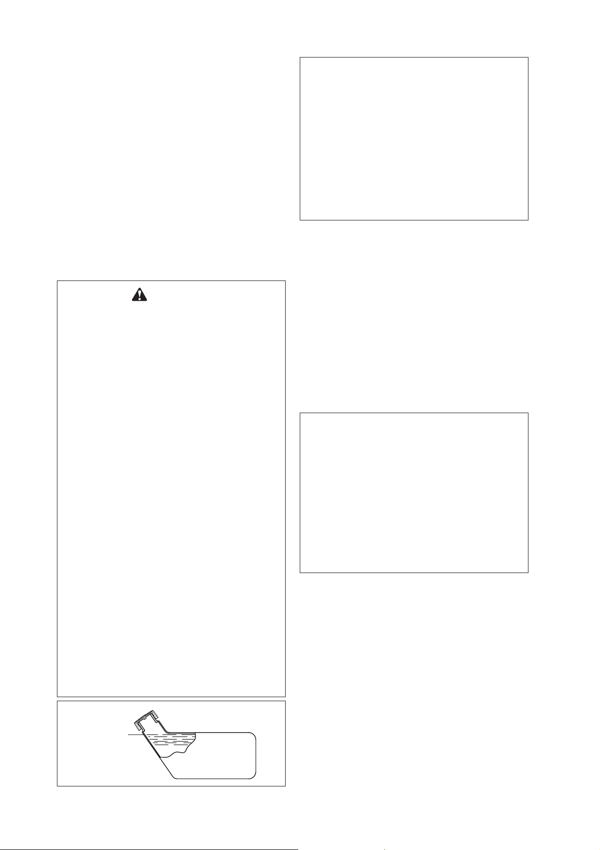
• DO NOT OVERFILL FUEL TANK. IT IS NOT
PERMITTED TO FILL FUEL ABOVE THE
SHOULDER LEVEL OF FUEL TANK. WIPE
UP SPILLS IMMEDIATELY.
• SECURELY TIGHTEN FUEL CAP AFTER
REFUELING.
• INSPECT FOR FUEL LEAKAGE.
IF FUEL LEAKAGE IS FOUND, DO NOT
START OR OPERATE UNIT UNTIL
LEAKAGE IS REPAIRED.
• MOVE AT LEAST 3 M (10 FEET) FROM
REFUELING LOCATION BEFORE
STARTING THE ENGINE.
IMPORTANT
• ECHO premium Power Blend X™ Universal
2-Stroke Oil may be mixed at 50 : 1 ratio for
application in all ECHO engines sold in the
past regardless of ratio specified in those
manuals.
• Use of unmixed, improperly mixed, or fuel
older than 90 days, (stale fuel), may cause
hard starting, poor performance, or severe
engine damage and void the product
warranty. Read and follow instructions in
the Storage section of this manual.
HANDLING FUEL
MIXING INSTRUCTIONS -
1. Fill an approved fuel container with half of the
required amount of gasoline.
2. Add the proper amount of two-stroke oil to
gasoline.
3. Close container and shake to mix oil with
gasoline.
4. Add remaining gasoline, close fuel container,
and remix.
IMPORTANT
• Spilled fuel is a leading cause of
hydrocarbon emissions. Some states may
require the use of automatic fuel shut-off
containers to reduce fuel spillage.
• Stored fuel ages.
Do not mix more fuel than you expect to
use in thirty (30) days, ninety (90) days
when a fuel stabilizer is added.
• Stored two-stroke fuel may separate.
ALWAYS shake fuel container thoroughly
before each use.
AFTER USE -
DO NOT store a unit with fuel in its tank. Leaks can
occur. Return unused fuel to an approved fuel
storage container.
STORAGE -
Fuel storage laws vary by locality. Contact your
local government for the laws affecting your area.
As a precaution, store fuel in an approved, airtight
container. Store in a well-ventilated, unoccupied
building, away from sparks and flames.
Shoulder level
Fuel tank
8
Page 11

STARTING COLD ENGINE
WARNING
WHEN ENGINE IS STARTED, CONFIRM IF
THERE IS NOT ANY ABNORMAL VIBRATION
OR SOUND. IF THERE IS ABNORMAL
VIBRATION OR SOUND, ASK YOUR DEALER
TO REPAIR.
• Stand the engine upright on a level surface.
Throttle trigger
Air cleaner
Purge bulb
Fuel return line
ON
STOP
Throttle trigger lockout
Push
Starter handle
Ignition switch
• Place ignition switch in ON (START/RUN)
position.
• Push purge bulb 3 to 4 times (or until fuel is
visible in fuel return line).
• Shift choke lever to close position (START).
• Pull starter handle until the engine fires.
• Shift choke lever to full open position, and if
necessary, start the engine again and allow to
warm up before using.
- The clutch engages at approximately 3500
r/min. Therefore the drill bit may rotate at
fast idle engine speed.
STARTING WARM ENGINE
• Place ignition switch in ON (START/RUN)
position.
• Pull starter handle until the engine fires.
- Do not use the choke.
RUN
(Open)
START
(Close)
Choke lever
STOPPING ENGINE
• Set throttle trigger in idle position.
• Place ignition switch in STOP position.
NOTE
When engine does not stop, shift choke lever to
close position.
Check and repair ignition switch before starting
the engine again.
9
Page 12
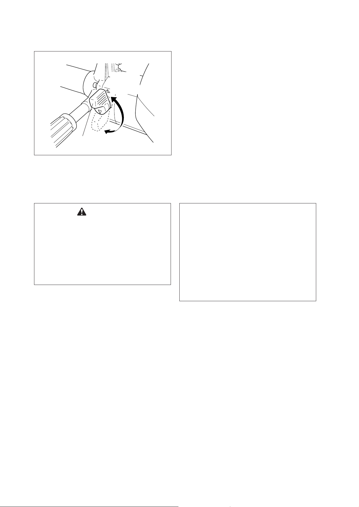
REVERSE ROTATION
• This model is equipped with reverse rotation
mechanism.
Counter
clockwise
(CCW)
Shift lever
Clockwise
(CW)
WARNING
• WHEN THE DRILL CAN NOT PULL OUT
FROM THE WOOD, DO NOT TRY TO PULL
OUT THE DRILL BY FORCE.
• WHEN CHANGING THE BIT, ENSURE TO
STOP THE ENGINE.
• When drilling, set shift lever down to clockwise
(CW) rotation position.
• If bit is locked due to deep penetration during
drilling operation, set shift lever up to
counterclockwise (CCW) rotation position and
operate reversed for easy pulling-out.
• When changing direction of drill rotation,
operate as follows:
- Return engine to idle.
- Engine shift lever to CW or CCW position
with a slight acceleration of the throttle
trigger.
To properly lock the gears in the gear case.
- Do not operate shift lever forcibly when
changing rotation direction.
NOTE
Do not shift from forward to reverse (or viceversa) while the chuck is turning.
Failure to do so may cause unit damage.
Always release throttle and allow the unit to
return to idle before shifting.
• AFTER A JOB, BIT AND GEAR CASING
MAY BE HEATED, DO NOT TOUCH THEM
WITH BARE HANDS.
Do not stand close to drill or chuck with your
body or clothes while operation.
When drilling, ensure that no power cable or
other obstacle exist.
10
Page 13

MAINTENANCE AND CARE
AREA MAINTENANCE PAGE BEFORE MONTHLY YEARLY DATE
USE MAINTENANCE
PERFORMED
Air Filter Clean/Replace 13 •
Fuel Filter Inspect/Clean/
Replace 13 •
Spark Plug Inspect/Clean/
Adjust/Replace 13 •
Carburetor Adjust 14 •
Cooling System Inspect/Clean 15 •
Silencer Inspect/Tighten/Clean 15 •
Starter Rope Inspect/Replace - •
Drills Inspect/Clean/
Lubricate - •
Fuel Leaks Inspect 13 •
Screws, Bolts and Inspect,
Nuts Tighten/Replace - •
Fuel Line Inspect - •
IMPORTANT
Time intervals are maximum. Actual use and
your experience will determine the frequency
of required maintenance.
Record dates of monthly and yearly
inspections.
11
Page 14

TROUBLE SHOOTING
Trouble
Engine - hard to start Cause Remedy
- does not start
Engine Fuel at No fuel • Fuel filter clogged • Clean or replace
cranks carburetor at carburetor • Fuel line clogged • Clean
• Carburetor • Ask your ECHO dealer
Fuel at No fuel at • Carburetor • Ask your ECHO dealer
cylinder cylinder
Silencer wet • Fuel mixture is too rich • Open choke
with fuel • Clean/replace air filter
• Adjust carburetor
• Ask your ECHO dealer
Spark at No spark at • Ignition switch off • Turn switch on
end of end of plug • Electrical problem • Ask your ECHO dealer
plug wire wire
Spark at No spark at • Spark gap incorrect • Adjust 0.6 to 0.7 mm
plug plug • Covered with carbon • Clean or replace
• Fouled with fuel • Clean or replace
• Spark plug defective • Replace plug
Engine • Internal engine problem • Ask your ECHO dealer
does not
crank
Engine Dies or • Air filter dirty • Clean or replace
runs accelerates poorly • Fuel filter dirty • Clean or replace
• Fuel vent blocked • Clean
• Spark plug • Clean and adjust/replace
• Carburetor • Adjust
• Cooling system blocked • Clean
• Exhaust port/spark • Clean
arrester screen blocked
WARNING
• ALL ENGINE DRILL SERVICE OPERATIONS, OTHER THAN ITEMS LISTED IN THE
OPERATOR’S MANUAL, SHOULD BE PERFORMED BY AN AUTHORIZED ECHO DEALER.
• FUEL VAPORS ARE EXTREMELY FLAMMABLE AND MAY CAUSE FIRE AND/OR
EXPLOSION. NEVER TEST FOR IGNITION SPARK BY GROUNDING SPARK PLUG NEAR
CYLINDER PLUG HOLE, OTHERWISE SERIOUS PERSONAL INJURY MAY RESULT.
12
Page 15

Air filter
Fuel filter
MAINTENANCE
AIR FILTER
• Clean before use.
- Remove air cleaner cover and pull out air
filter.
- Lightly brush off dust or wash it in water and
detergent.
- Dry completely before putting it back in
place.
Air cleaner cover
FUEL FILTER
• Check periodically.
- Do not allow dust to enter into fuel tank.
- Clogged filter will cause difficulty in starting
engine or poor engine performances.
- Pick up fuel filter through fuel inlet port with
a piece of steel wire or the like.
- When filter is dirty, replace it.
Fuel tank cap
0.6 - 0.7 mm
CHECK FUEL SYSTEM
• Check before every use.
• After refueling, make sure fuel does not leak or
exude from around fuel pipe, fuel grommet or
fuel tank cap.
• In case of fuel leakage or exudation there is a
danger of fire. Stop using the machine
immediately and request your dealer to inspect
or replace.
SPARK PLUG
• Check periodically.
- The standard spark gap is 0.6 to 0.7 mm.
- Correct spark gap if it is wider or narrower
than the standard gap.
- If the electrodes are coated with carbon
deposits replace with a new spark plug.
Do not sandblast to clean.
Remaining sand will damage engine.
• Fastening torque = 15 to 17 N · m
IMPORTANT
Do not over tighten plug.
13
Page 16

REPLACEMENT OF CHUCK
Replacement of chuck should be done in the
following manner:
1. Remove bolt with hexagonal hole fixed in the
driving axle.
2. Insert accessory hexagonal bar (Part Number
895412-20960) into chuck and fix.
3. Fit 19 mm spanner onto driving axle and keep
it fitted.
4. Fit 10 mm box spanner onto the hexagonal bar
and turn it into direction as indicated by an
arrow to remove chuck.
5. Fit a new chuck in the reversed order of
removing.
Box spanner
(10 mm)
Hexagonal bar
(Part Number 895412-20960)
Spanner (19 mm)
ADJUSTING CARBURETOR
(As Required)
GENERAL INFORMATION
The idle speed adjuster screw controls the throttle
opening at the idle position.
IDLE ADJUSTMENT
Start engine and allow it to run at high idle until
warm.
Idle speed adjustment screw
1. Turn the idle speed screw clockwise until drill
bit begins to move.
2. Turn idle screw counterclockwise 1/2 turn or
until the drill bit stops (2700 to 3300 r/min).
NOTE
When there is some trouble with the carburetor,
contact your dealer.
14
Page 17

CLEANING CYLINDER FINS
(Check Periodically)
NOTE
Clogged fins will cause poor engine cooling.
1. Carefully remove housing and clean dirt and
dust from fins.
2. Reinstall housing.
STORAGE
CLEANING SILENCER AND
EXHAUST PORT (Check
Periodically)
1. Carefully remove housing halves.
2. Remove and disassemble silencer.
NOTE
Be careful not to scratch the cylinder or piston
when cleaning the cylinder exhaust port.
3. Clean deposits from cylinder exhaust port and
silencer.
LONG TERM STORAGE
(Over 30 Days)
Do not store your unit for a prolonged period of
time (30 days or longer) without performing
protective storage maintenance which includes the
following:
1. Store unit in a dry, dust free place, out of the
reach of children and other unauthorized
persons.
2. Place ignition switch in STOP position.
3. Remove accumulation of grease, oil, dirt and
debris from exterior of unit.
4. Perform all periodic lubrication and services
that are required.
5. Tighten all the screws, bolts and nuts.
WARNING
DO NOT STORE IN AN ENCLOSURE WHERE
FUEL FUMES MAY ACCUMULATE OR
REACH AN OPEN FLAME OR SPARK.
6. Drain the fuel tank completely and pull the
recoil starter handle several times to remove
fuel from the carburetor.
7. Remove the spark plug and pour 1/2
tablespoon of fresh, clean, 2-stroke engine oil
into the cylinder through the spark plug hole.
A. Place a clean cloth over the spark plug hole.
B. Pull the recoil starter handle 2 or 3 times to
distribute the oil inside the engine.
C. Observe the piston location through the
spark plug hole. Pull the recoil starter handle
slowly until the piston reaches the top of its
travel and leave it there.
8. Install the spark plug (do not connect ignition
cable.)
9. Lubricate the drill bit with a heavy coat of oil to
prevent rust.
NOTE
For future reference, you should keep this
operator’s manual.
15
Page 18

SPECIFICATIONS
EDR-210
Mass
without drill bit kg 4.6 (10.1 lbs )
Volume
fuel tank L 0.5 (16.9 US, fl. oz.)
Drill
size mm 32 - 178 (1.25 - 7 inch)
chuck capacity mm 13 (0.5 inch)
speed r/min 520
Mission
reduction ratio 17.1 (regular side)
18.6 (reverse side)
lubrication grease
External Dimensions
length × width × height mm 430 × 320 × 265
without drill bit (16.9 × 12.6 × 10.4 inch)
Engine
type Air cooled Two stroke single cylinder
engine displacement mL(cm³) 21.2 (1.29 cu. inch)
recommended maximum engine speed r/min 9000
recommended engine idling speed r/min 2900
engine speed at beginning of clutch engagement r/min 4000
carburetor diaphragm type
ignition flywheel magneto - CDI system
spark plug NGK BPMR8Y
starter recoil starter
clutch automatic Centrifugal
Fuel
mixture ratio 50:1 ratio with ECHO Power Blend X™ ,
ISO-L-EGD (ISO/CD 13738) and JASO
M345-FC/FD two-stroke, air-cooled engine
oil.
gasoline Use 89 octane unleaded. Do not use fuel
containing methyl alcohol, more than 10%
ethyl alcohol or 15% MTBE. Do not use
alternative fuels such as E-20 or E-85.
fuel consumption at engine maximum power L/h 0.47 (15.9 US, fl. oz.)
16
 Loading...