

Page 1
Chain Saw
Instruction Manual
MODELS : CS-3000 TYPE 1E
Serial Number 665926 - 999999
CS-3400 TYPE 1E
Serial Number 593342 - 999999
CS-3450 TYPE 1E
Serial Number 617762 - 999999
X7503200008
WARNING
Read rules for safe operation and instructions carefully. ECHO provides an Instruction
Manual and a Safety Manual. Both must be read and understood for proper and safe
operation.
DANGER
X750001412
06/02
Page 2

RULES FOR SAFE OPERATION
A. Kickback Safety Precaution for Chain Saw Users
WARNING!
KICKBACK may occur when the nose or tip of the
guide bar touches an object, or when the wood
closes in and pinches the saw chain in the cut.
Tip contact in some cases may cause a lightning
fast reverse REACTION, Kicking the guide bar up
and back towards the operator . Pinching the saw
chain along the top of the guide bar may push the
guide bar rapidly back towards the operator. Either of these reactions may cause you to lose control of the saw which could result in serious personal injury .
Do not rely exclusively upon the safety devices built
into your saw. As a chain saw user , you should take
several steps to keep your cutting jobs free from
accident or injury .
1. With a basic understanding of kickback, you
can reduce or eliminate the element of surprise.
Sudden surprise contributes to accidents.
2. Keep a good firm grip on the saw with both
hands, the right hand on the rear handle, and
the left hand on the front handle, when the engine is running. Use a firm grip with thumbs and
fingers encircling the chain saw handles. A firm
grip will help you reduce kickback and maintain control of the saw . Don’t’ let go.
3. Make sure that the area in which you are cutting is free from obstructions. Do not let the
nose of the guide bar contact a log, branch, or
any other obstruction which could be hit while
you are operating the saw.
4. Cut at high engine speeds.
5. Do not overreach or cut above shoulder height.
6. Follow manufacturer’s sharpening and maintenance instructions for the saw chain.
7. Only use replacement bars and chains specified by the manufacturer or the equivalent.
B. Other Safety Precautions
1. Do not operate a chain saw with one hand! Serious injury to the operator, helpers, byst anders, or any combination of these persons may
result from one-handed operation. A chain saw
is intended for two-handed use.
2. Do not operate a chain saw when you are fatigued.
3. Use safety footwear; snug-fitting clothing; protective gloves; and eye, hearing and head protection devices.
4. Use caution when handling fuel. Move the chain
saw at least 10 feet (3 m) from the fueling point
before starting the engine.
5. Do not allow other persons to be near the chain
saw when starting or cutting with the chain saw .
Keep bystanders and animals out of the work
area.
6. Do not start cutting until you have a clear work
area, secure footing, and a planned retreat path
from the falling tree.
2
Page 3

7. Keep all parts of your body away from the saw
chain when the engine is running.
14.Keep the handles dry , clean, and free of oil or
fuel mixture.
8. Before you start the engine, make sure that
the saw chain is not contacting anything.
9. Carry the chain saw with the engine stopped,
the guide bar and saw chain to the rear , and
the muffler away from your body .
10.Do not operate a chain saw that is damaged,
improperly adjusted, or not completely and
securely assembled. Be sure that the saw
chain stops moving when the throttle control
trigger is released.
11.Shut off the engine before setting the chain saw
down.
12.Use extreme caution when cutting small size
brush and saplings because slender material
may catch the saw chain and be whipped toward you or pull you off balance.
13.When cutting a limb that is under tension, be
alert for spring back so that you will not be
struck when the tension in the wood fibers is
released.
15.Operate the chain saw only in well-ventilated
areas.
16.Do not operate a chain saw in a tree unless
you have been specifically trained to do so.
17.All chain saw service, other than the items listed
in the Instruction Manual maintenance instructions, should be performed by competent chain
saw service personnel. (For example, if improper tools are used to remove the flywheel
or if an improper tool is used to hold the flywheel in order to remove the clutch, structural
damage to the flywheel could occur and could
subsequently cause the flywheel to burst.)
18.When transporting your chain saw, use the
appropriate guide bar scabbard.
19.Spark arrester mufflers approved to SAE Standard J335b are Standard on ECHO Chain
saws to reduce the possibility of forest fires.
Do not operate the chain saw with a loose or
defective muffler . Do not remove the spark arrester screen.
CONTENTS
Page
Rules for Safe Operation..................................................................................................2
T echnical Data .................................................................................................................4
Nomenclature of Parts...................................................................................................... 5
Preparation for Use.......................................................................................................... 6
Fuel and Lubricant............................................................................................................ 7
Operation......................................................................................................................... 8
Cutting Instructions .........................................................................................................10
Maintenance and Care...................................................................................................14
Chain and Guide Bar Combinations...............................................................................17
Setting the Saw Chain....................................................................................................17
Troubleshooting..............................................................................................................19
Storage..........................................................................................................................20
Correct Use of Chain Brake ...........................................................................................21
Servicing Information...................................................................................................... 24
3
Page 4

TECHNICAL DATA
ledoME-1EPYT0003-SCE-1EPYT0043-SCE-1EPYT0543-SC
noisnemiDHxWxLmm022x032x062542x032x083
hcni7.8x1.9x2.016.9x1.9x0
thgieWyrd,daehrewoPgk)bl1.7(2.3)bl3.7(3.3)bl5.7(4.3
enignEepyTccrednilycelgnis,ekort
tnemecalpsiD).ni.uc38.1(1.03).ni.uc30.2(4.33
roterubraC
otengaM
gulPkrapS
retratS
rtrewoP
leuFoitar
liOniahcdnaraB)liorotomro(lioniahcdnarabOHCE
rabediuG
erutxiM.lioekorts-owtdnarbOHCEhtiwoitar1:05
noissimsna
yticapaCknaTretil).S.Uzolf6.8(52.0
yticapaCknaTretil).S.U.zo.lf5(51.0
s-owt,delooc-riA
epytmgarhpaiD
metsysIDC:otengamleehwylF
A7-MPBKGN
retratslioceR
hctulclagufirtneccitamotuA
51rolohoclalyhte%01nahterom
dradnatS.ni21dradnatS.ni41dradnatS.ni61
.51
rabediugdnaniahctuohtiW
,lohoclalyhtemgniniatnocleufesutonoD.dedaelnuenatco98
.EBTM%
niahcwaS
noitacirbuLpmupliocitamotuaelbatsujdA
dradnatS
serutaef
* Technical data subject to change without notice.
lanoitpO.ni61,41l
eldnaHpoTeldnahlanoi
,draugdnahtnorF
,ecivednoitarbiv-itnA
errakrapS,rehctacniahC
anoitpO.ni61,21lanoitpO.ni41,21
tnevnoC
draugdnahraeR
,ekarbniahC,tuokcollortnocelttorhT
relffumrots
4
Page 5
CS-3000, CS-3400
18
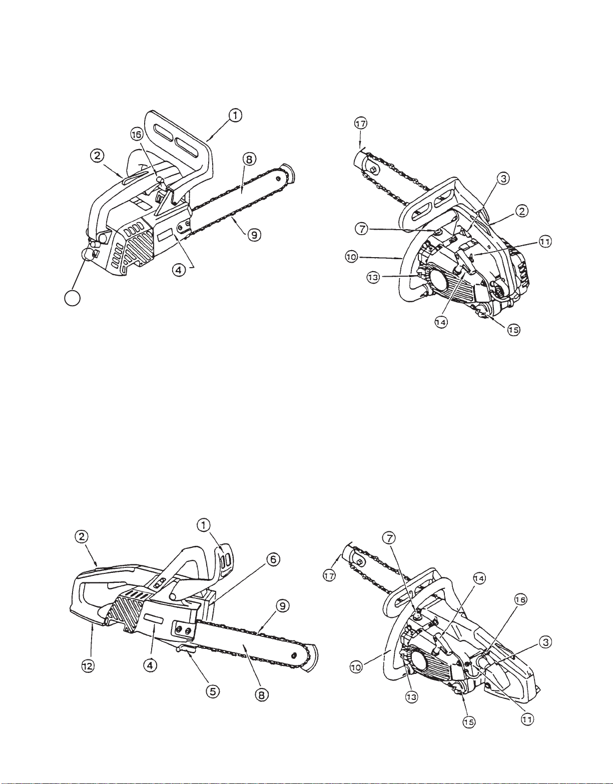
NOMENCLATURE OF P ARTS
1. Hand guard
(Chain brake actuating lever)
2. Throttle control lockout
3. Throttle control trigger
4. Sprocket guard
5. Chain catcher
CS-3450
6. Air cleaner cover
7. Purge bulb
8. Guide bar
9. Saw chain
10. Front handle
1 1 . On / Off switch
12. Rear hand guard
13. Fuel tank cap
14. Pull starter
15. Oil tank cap
16. Throttle control latch
17. Tip guard
18. Lanyard ring
5
Page 6
PREPARA TION FOR USE
The machine may be delivered with guide bar (A) and saw
chain (B) separated. Install guide bar and saw chain as
follows:
A
W ARNING DANGER
Saw Chain is sharp! Always wear gloves when
handling assembly, otherwise serious personal injury
may result.
B
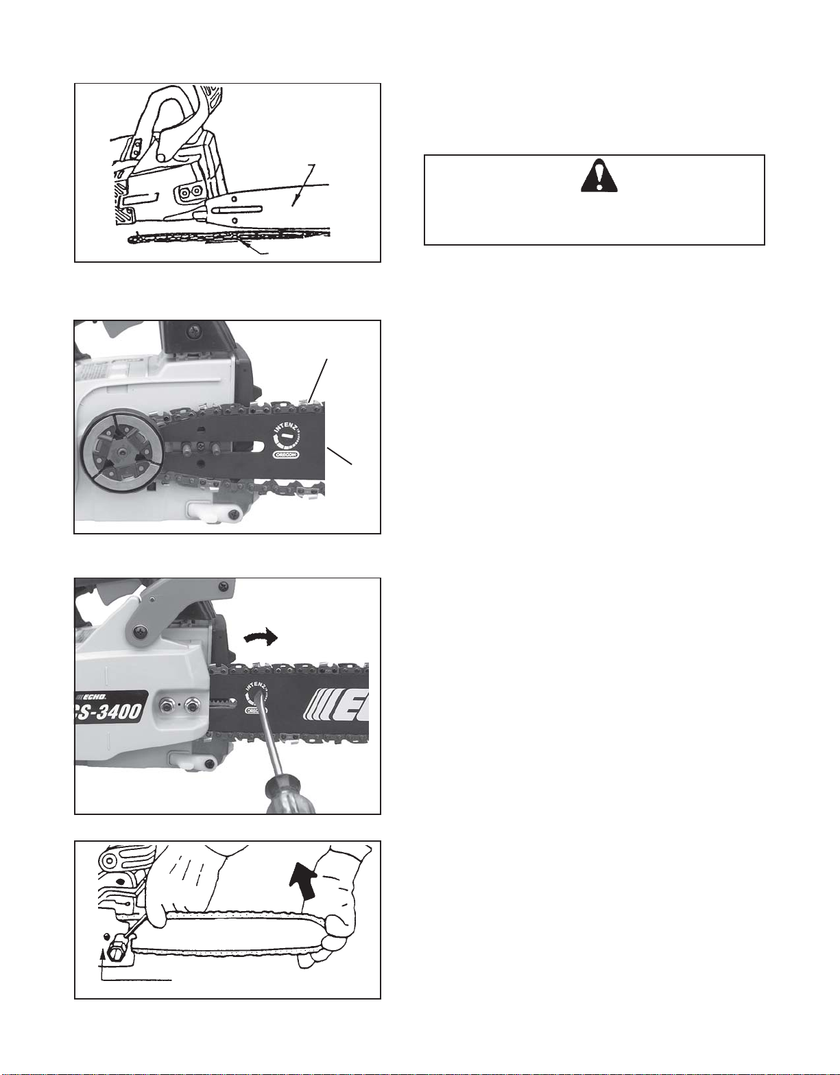
GUIDE BAR AND SAW CHAIN
UP
B
A
• Follow the instructions enclosed with tip guard to
install guard to guide bar .
• Remove two guide bar nuts and remove sprocket
guard (C).
• Mount guide bar (A) on studs, and slide toward
sprocket to make saw chain installation easier .
• Install saw chain (B) as shown, with cutters facing
forward.
NOTE
Chain brake must be in fully released position to install
sprocket guard to saw.
• Install sprocket guard (C), and tighten guide bar nuts
finger tight.
• Adjust saw chain tension, as instructed in “Adjustment, Chain T ension.”
ADJUSTMENT, CHAIN TENSION
• Loosen two guide bar nuts.
• Turn the adjuster slot clockwise until the chain
touches the bottom of the bar.
• Hold the bar nose up and tighten the chain until there
is no clearance between the bar and chain.
• Tighten both guide bar nuts with bar nose held up, to
eliminate clearance.
• Pull the saw chain around the guide bar by hand.
Loosen the adjustment, if you feel tight spots.
• Start the engine and run at low speed. Stop and
readjust, if necessary .
CAUTION
1. All adjustments should be made cold.
2. Always wear gloves when working on chain.
3. Do not operate with a loose chain.
C
6
Page 7
FUEL AND LUBRICANT
).S.U()CIRTEM(
SAGLIOSAGLIO
.laG.zo.lFretiL.cc
1
2
5
6.2
1.5
8.21
4
8
02
08
061
004
FUEL STATEMENT
Gasoline - Use 89 Octane [R+M/2] (mid grade or higher)
gasoline known to be good quality. Gasoline may contain up to
15% MTBE (methyl tertiary-butyl ether). Gasohol containing
methyl (wood) alcohol is NOT approved.
Oil
Two Stroke Oil - A two-stroke engine oil meeting ISO-L-EGD
(ISO/CD 13738) and J.A.S.O.
Echo brand Premium 50:1 oil meets these standards. Engine
problems due to inadequate lubrication caused by failure to use
an ISO-L-EGD and J.A.S.O.
Premium 50:1 Two-stroke Oil, will void the two-stroke engine
warranty. (Emission related parts
years, regardless of two-stroke oil used, per the statement
listed in the EPA Phase I Emission Defect Warranty Explanation.)
IMPORTANT
Echo Premium 2-Stroke Oil may be mixed at 50:1 ratio
for application in all Echo engines sold in the past regardless of ratio specified in those manuals.
Mixing Instructions
1. Fill an approved fuel container with half of the required
amount of gasoline.
2. Add 2-stroke oil to gasoline.
3. Close container and shake to mix oil with gasoline.
4. Add remaining gasoline and remix.
5. Install fuel container cap and wipe any spilled fuel from
container and surrounding area.
IMPORTANT
Stored fuel ages. Do not mix more fuel than you expect to
use in thirty (30) days, ninety (90) days when a fuel stabilizer is added.
FC Standards, must be used.
FC certified oil, such as Echo
only are covered for two
50
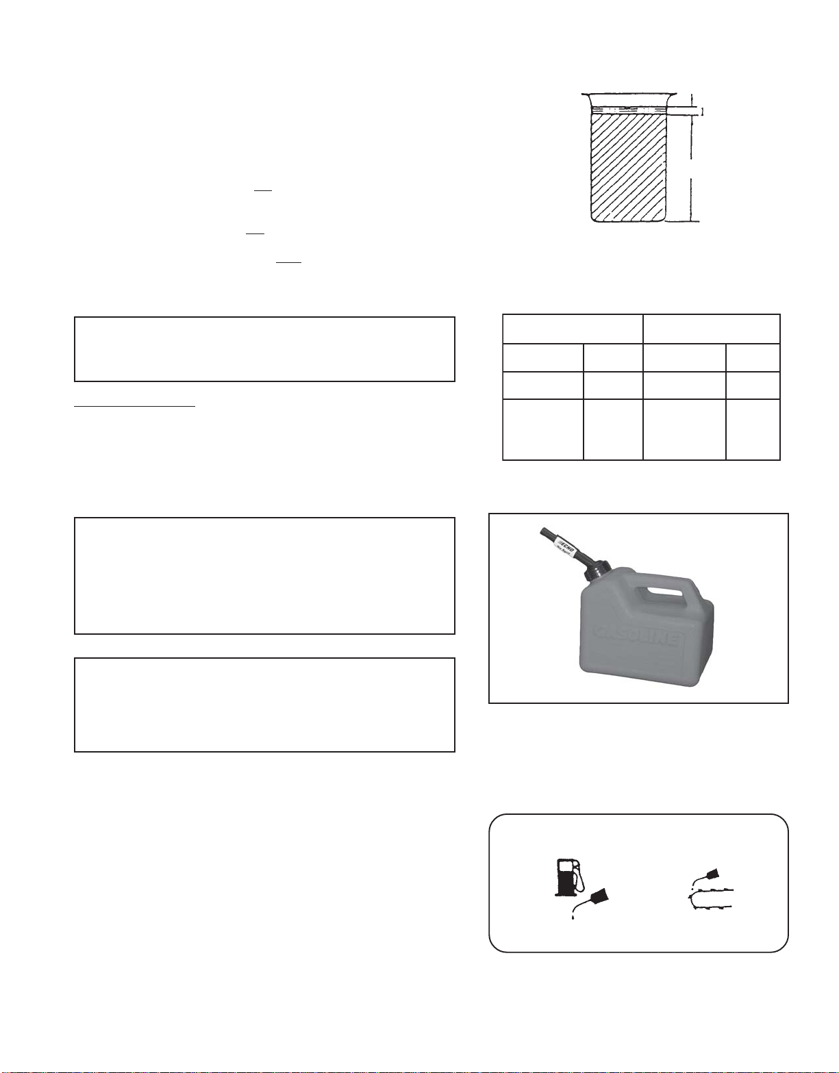
Gasoline
Fuel Mix Chart
50:1
Stored two-stroke fuel may sep arate. ALWAYS shake fuel
container thoroughly before each use.
IMPORTANT
Spilled fuel is a leading cause of hydrocarbon emissions.
Some states may require the use of automatic fuel shutoff containers to reduce fuel spillage. Contact your ECHO
dealer for ordering information.
CHAIN LUBRICANT
Proper lubrication of the chain while in operation reduces friction
between the chain and the guide bar to a minimum and assures
a longer service life.
• Use high quality ECHO bar and chain oil for this purpose.
• Do not use used or reclaimed oil to avoid various oiler
problems.
• Use bar and chain oil of the following grades:
SAE NO. 30 ..... in summer
SAE NO. 10 ..... in winter or when cutting resinous trees.
• When refueling, also refill chain oil.
T ANK INDICATION
FUEL T ANK OIL T ANK
7
Page 8
OPERATION
WHEN THE ENGINE IS COLD
• Move chain brake lever fully forward to engage chain
brake before starting.
• Fill the fuel tank with fuel.
• Fill the chain oil tank with lubricant.
• Turn switch (A) to “RUN” position.
• Pull choke (B) all the way out (close position).
• Push purge bulb (C) 10 times.
• Pull starter handle several times until first firing sound.
(Hold machine with your knee or foot.)
• Push choke (B) all the way in. (open position)
• Pull starter handle again.
CS-3450
CS-3000
CS-3400
A
A
WHEN THE ENGINE IS HARD TO START
• Press throttle control lockout down while holding
throttle trigger, and push in throttle control latch.
• Pull starter handle.
• When engine starts, immediately squeeze throttle
trigger to release the latch.
CAUTION
Clutch engages and chain will rotate when engine is started
with throttle control latch engaged.
After engine starts, release throttle trigger to idle engine.
Never use the throttle control latch for cutting.
Use only when starting the engine.
Make sure bar and chain are not touching anything when
starting the saw.
Do not pull starter rope out to the maximum possible
position.
Do not allow recoil handle to snap back against the casing.
C
B
Securely hold the saw.
8
Page 9
STARTING WARM ENGINE
• Ensure that there is fuel and chain oil in the tanks. (If fuel
tank was emptied during previous operation, refill tank and
push purge bulb 10 times.)
• Turn switch (A) to “RUN” position.
• Pull starter handle.
• Choke may be used if necessary , but be sure to push it
back on first firing sound.
NOTE
If engine does not start after 5 pulls, use cold start
procedure.
RUNNING
• After engine starts, allow it to return to idle.
• Move chain brake lever fully rearward to release chain
brake.
• Squeeze throttle trigger with throttle control lockout
gradually to increase engine speed.
• Saw chain starts moving when the engine reaches
approximately 4200 rpm.
• Ensure proper acceleration and lubrication of chain and
bar.
• Do not run the engine at high speed unnecessarily .
• Be sure that saw chain stops moving when throttle trigger
is released.
CS-3450
CS-3000
CS-3400
A
A
STOPPING
• Release throttle trigger and turn switch (A) to STOP
position.
NOTE
If engine does not stop, pull choke out fully to stop
engine.
Check and repair stop switch before starting the engine
again.
A
CS-3450
CS-3000
CS-3400
A
9
Page 10

GENERAL
CUTTING INSTRUCTIONS
[NOTE]
Read the ECHO “CHAIN SAW SAFETY MANUAL” included with
your chain saw for additional cutting and safety instructions.
In all circumstances the operation of the chain saw is a oneman job. It is difficult at times to take care for your own safety,
so don’t assume the responsibility for a helper as well. After
you have learned the basic techniques of using the saw, your
best aid will be your own good common sense...
The accepted way to hold the saw is to stand to the left of the
saw with your left hand on the front handlebar and your right
hand on the rear handle so you can operate the throttle trigger
with your right index finger.
Before attempting to fell a tree, cut some small logs or limbs.
Become thoroughly familiar with the controls and the responses of the saw.
St art the engine, see that it is running properly . Squeeze the
trigger to open the throttle wide open and start the cut. If the
chain is properly sharpened, the cutting should be relatively
effortless. It is not necessary to press down hard to make the
saw cut. Pushing the saw too hard will slow the engine and
cutting will actually be more difficult.
Kickback
Some material may adversely affect the housings of your
ECHO chain saw.
(Example: Palm Tree Acid, fertilizer, etc.) To avoid housing
deterioration, carefully remove all packed saw dust around
clutch and guide bar area and wash with water.)
CAUTION
Do not let the tip of the bar touch anything while the engine is
running. At cutting speed the chain is moving, at a high rate of
speed. Should the tip contact a limb or log while the chain is
moving, the tip will be pushed upward with considerable force.
This is known as kickback. Avoid it!
CAUTION
Wear suitable hearing protective device such as ear muffs or ear
plugs to protect against objectionable or uncomfortable loud noises.
10
Page 11

FELLING A TREE
DIRECTION
OF FALL
Direction of fall
First cut
Notch
Second cut
One-third tree
diameter
2”
45°
Hinge
Felling cut
2”
CAUTION
A falling tree can seriously damage anything it may hit - a
car, a house, a fence, a power line, or another tree. There
are ways to make a tree fall where you want it, so first
decide where that is!
Before cutting, clear the area around the tree. Y ou will need
good footing while working and you should be able to work
the saw without hitting any obstacles. Next, select a path
of retreat. When the tree begins to fall you should retreat
away from the direction of fall at a 45 degree angle to avoid
the trunk kicking back over the stump.
Begin the cut on the side to which the tree is to fall. Cut a
notch about 1/3 of the way into the tree as shown. The
position of this notch is important since the tree will try to
fall “into” the notch. The felling out is made on the side
opposite the notch and at a level about 2” above the bottom
of the notch. Do not try to cut through to the notch with the
felling cut. The remaining wood between the notch cut and
felling cut (about 2”) will act as a hinge when the tree falls,
guiding it in the desired direction. When the tree starts to
fall, kill the engine, place the saw on the ground and make
your retreat quickly .
LIMBING
To fell big trees with a diameter exceeding twice the bar
length, start the notching cuts from one side and draw the
saw through to the other side of the notch. Start the back
cut on one side of the tree, pivoting the saw through to form
the desired hinge on that side.
Then remove the saw for the second cut. Insert the saw in
the first cut, very carefully so as not to cause kickback.
The final cut is made by drawing the saw forward in the cut
to reach the hinge.
Limbing a fallen tree is much the same as bucking. Never
limb on the tree that you are standing. When limbing, caution is the word. Be careful of the tip touching other limbs.
Always use both hands.
11
Page 12

Don’t cut with the saw overhead or the bar in a vertical position. If the saw should kick back you may not have good
enough control to prevent possible injury .
BUCKING
Uphill position
FIRST CUT
KICKBACK
FINISH CUT
Board or flat stones
Bucking is the sawing of a log or fallen tree into smaller
pieces. There are a few basic rules which apply to all
bucking operations.
Keep both hands on the handles at all times.
Support logs if possible.
When cutting on a slope or hillside, always stand uphill.
Keep in mind that the wood is heavy and that it will bend and
pinch the saw if improperly supported.
The trunk will weaken at the point where you make the cut
unless the tree is lying on perfectly flat ground or supported
as shown.
If you make the cut with the tree on the ground, don’t let the
saw’s chain dig into the earth; it is harmful for the saw , and
you stand a good chance of being struck by flying debris. To
cut the trunk, use the bucking and two-cut sequence shown.
The first cut should be no deeper than one-third the trunk
diameter.
• Improper thrust cutting.
• When the bar nose hits another tree, etc.
WARNING: KICKBACK IS DANGEROUS
Kickback is generated when the rotation of the chain is arrested for some reason. The most dangerous effect of this
action occurs when the nose of the bar contacts another object, the chain is momentarily stopped and all the energy of
the engine throws the bar upwards and backwards towards
the operator.
The chain saw industry and government agencies have attempted to prescribe various safety devices, but the best protection is to avoid kickback.
Comply with the Safety Precautions as listed on page 2 of
this manual.
12
Page 13

INFORMATION
Kickback Safety Features
The following features are recommended for this model as Kickback Safety Features.
• Double Guard Low Kick T ype Guide Bar or Asymmetrical Low Kick T ype Guide Bar
Note: Y our saw chain can be equipped with either of these bars.
Double Guard Bar
Reduced nose
radius
NOTE
Use Oregon
The following guide bars may be considered to have equivalent kickback energy .
• Sprocket nose guide bars of the same length and nose radius, same pitch and having the same number of teeth.
• A hard nose guide bar having the same length and nose radius as a sprocket nose bar .
®
IntenzTM replacement guide bars.
• Low Kick Guard Link Type Saw Chain
The low kick guard link chain must be maintained correctly . Follow instruction “SETTING THE CHAIN” in Instruction
Manual.
• Front Handle Guard
The front handle guard must be installed correctly and kept in good condition.
• Chain Brake
Chain brake must be maintained correctly . Follow instruction “CORRECT USE OF CHAIN BRAKE” in Instruction
Manual.
CAUTION !!
The consequences of using improper replacement components and of removing safety devices may result in serious
or fatal injury
13
Page 14

MAINTENANCE AND CARE
C
A
AIR FILTER
• Check before every use.
• Pull choke (A) all the way out (close position).
• Loosen bolt and remove air cleaner (B) cover and filter (C).
• Lightly brush dust off filter, and inspect for damage.
AUTOMATIC OILER
B
D
• The discharge volume of the automatic oiler is adjusted to 3
to 4 cc/mm (@ 7000 rpm) prior to shipment from the factory.
• Always check oil discharge when in use.
• Turn adjusting screw (D) counter-clockwise to increase oil
volume, clockwise to decrease oil volume.
OIL STRAINER
• Check periodically.
- Do not allow dust to enter into oil tank.
- Clogged oil strainer will affect the normal lubricating
system.
- Pick it up through oil port.
- If the strainer (E) is dirty, wash it in gasoline.
- When the inside of the tank gets dirty, rinsing the tank
out with gasoline will clean it.
E
FUEL STRAINER
• Check periodically.
- Do not allow dust to enter fuel tank.
- Clogged strainer will cause difficulty in starting engine or
abnormalities in engine performance.
- Pick up the fuel strainer (F) through fuel inlet port with a
piece of steel wire, or the like.
- When the strainer is dirty, wash it in suitable cleaning
fluid.
- When the inside of the fuel tank is dirty, rinsing the tank
out with suitable cleaning fluid will clean it.
GUIDE BAR AND OIL HOLES
• Clean after each use
- Clean the grooves (G) of the guide bar with, for example,
a small screwdriver.
- Clean oil holes (H) with a wire.
• Reverse guide bar periodically.
SPROCKET
F
H
G
• A damaged sprocket (J) will cause premature damage or
wear of saw chain.
- When the sprocket has worn out 0.5mm (.020”) or more,
replace it.
• Check sprocket when you install new chain. Replace it if
worn.
• Clean sprocket, clutch and bar mount area before installation
of bar.
IMPORTANT
Some tree sap and resins are corrosive. Thoroughly wash the
guide bar and sprocket areas after each use, then coat metal
J
parts with light oil.
14
Page 15
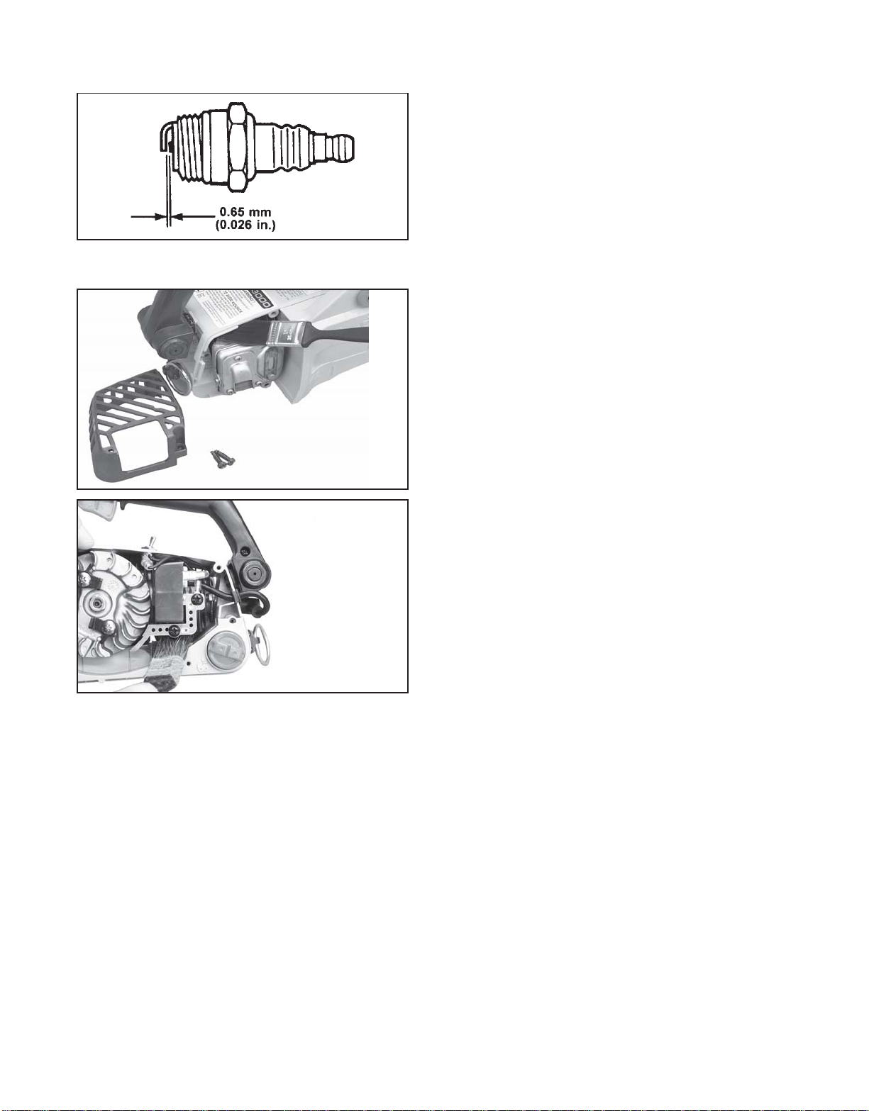
SPARK PLUG
• Check periodically
• Gap = 0.65mm (.026”)
• Replace if either electrode is worn, or if the insulator
is fouled by oil or other deposits.
• Torque = 145 – 155 kg*cm (125 – 135 in. lb.)
CAUTION: Do not over-torque.
COOLING SYSTEM CLEANING
• Remove spark plug lead.
• Remove muffler cover.
• Remove recoil starter housing.
• Use a stiff bristle cleaning brush (do not use a metal
brush) to remove dirt from cylinder fins in muffler and
ignition coil areas.
CARBURETOR ADJUSTMENT
ENGINE BREAK-IN
New engines must be operated a minimum duration of two
tanks of fuel break-in before carburetor adjustments can be
made. During the break-in period your engine performance
will increase and exhaust emissions will stabilize. Idle speed
can be adjusted as required.
HIGH ALTITUDE ADJUSTMENT
High altitude adjustment is not required for proper operation
of this engine.
15
Page 16
Before starting the unit for adjustment, check the following
items:
• The correct spark plug must be clean and properly
gapped.
• The air filter element must be clean and properly
installed.
• The muffler spark arrestor screen and exhaust port
must be clear of carbon.
• The standard bar and chain combination (see page 4)
must be installed to the power head, and properly
tensioned.
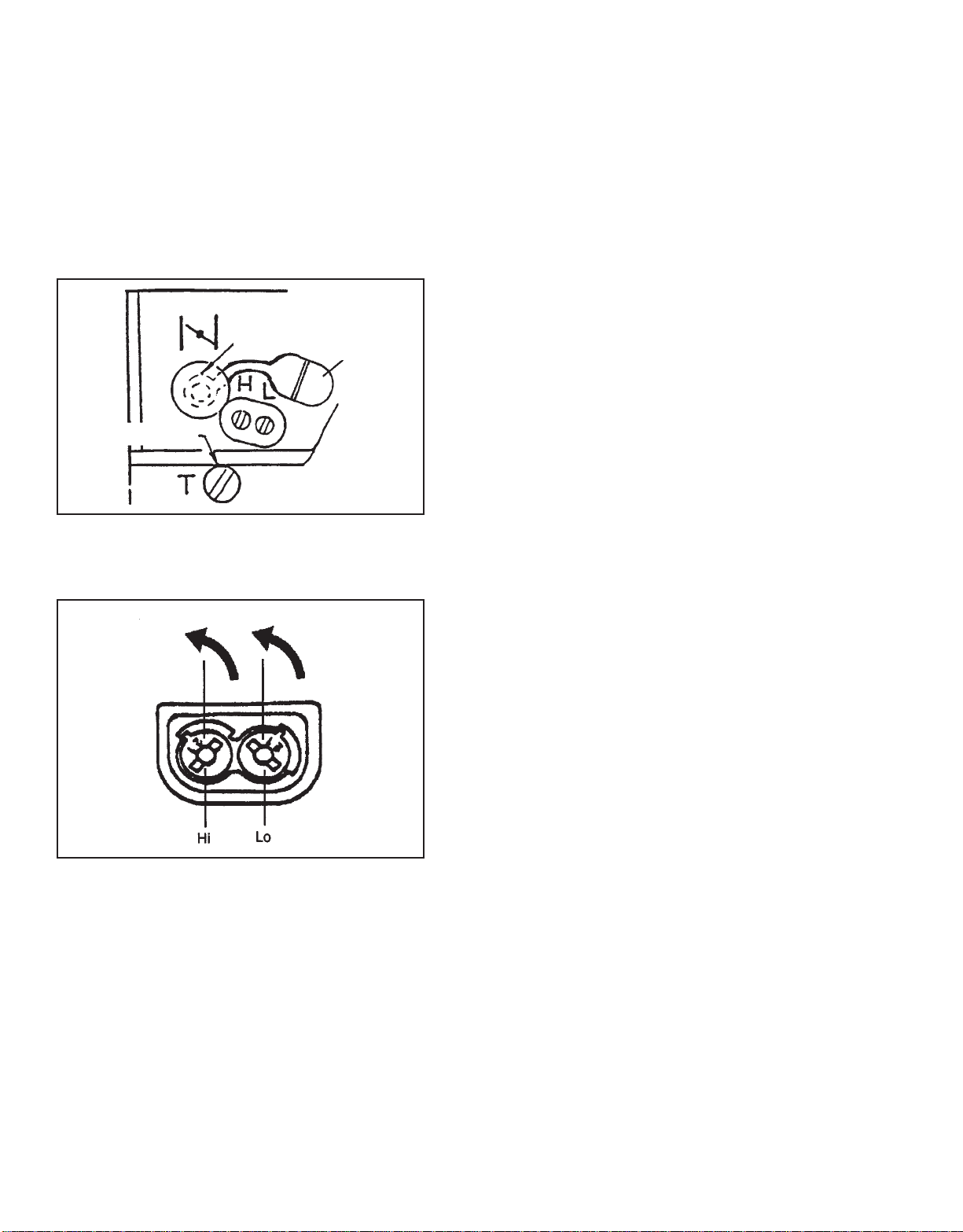
A
1. Start engine and run for several minutes to reach
operating temperature.
2. Stop engine. Remove grommet cover (A) over “H” and
B
“L” limiter needles.
3. Turn HI speed needle (H) CCW (counter clockwise) to
stop. Turn LO speed needle (L) CCW (counter clockwise) to stop.
4. Idle Speed Adjustment.
• Start engine and turn “idle” speed adjustment screw
(B) CW until the saw chain begins to move, then turn
the screw CCW until saw chain stops moving. Turn
screw CCW an additional 1/4 turn.
5. Accelerate to full throttle for 2-3 seconds to clear
excess fuel from engine then return to idle. Accelerate
to full throttle to check for smooth transition from idle
to full throttle. If engine stops or stalls after full warm
up return the unit to your authorized ECHO dealer for
repair.
6. Install grommet cover (A) over “H” and “L” limiter
needles.
7. Check HI speed RPM at W.O.T. (Wide Open Throttle).
HI speed RPM should be set between 10,500 and
11,500 RPM’s.
8. Check idle speed and reset if necessary. If a tachometer is available, idle speed should be set between
2,700 and 3,300 RPM’s.
CAUTION!
• When starting, idling adjustment speed should be
adjusted not to rotate the saw chain.
• When there is trouble with the carburetor, refer to your
distributor or dealer.
16
Page 17
CHAIN AND GUIDE BAR COMBINATION
The following combinations may be used on CS-3000, CS-3400 or CS-3450.
ledoM
htgneLN/POHCE
0003-SC
0043-SC
0543-SC
*Reduced nose radius symmetrical bars (
.ni21
.ni41
.ni61
raBediuG
Oregon
05473221*
1
102573241*
107573261*
®
name — Double Guard)
hctiP
niahCwaS
rebmuN
drauGkciK
rebmuN
eguaG
050.8/3
050.8/3
050.8/3
X54-GV19
X25-GV19
X75-GV19
94982
94982
94982
WARNING DANGER
Use of replacement saw chain and/or guide bar other than that specified, or operation without the “tip guard” in place, may
cause severe kickback resulting in serious injury.
Only use saw chain designated as, “LOW-KICKBACK,” that meets the ANSI B175.1-2000 Standard, and the Echo guide bar
specified.
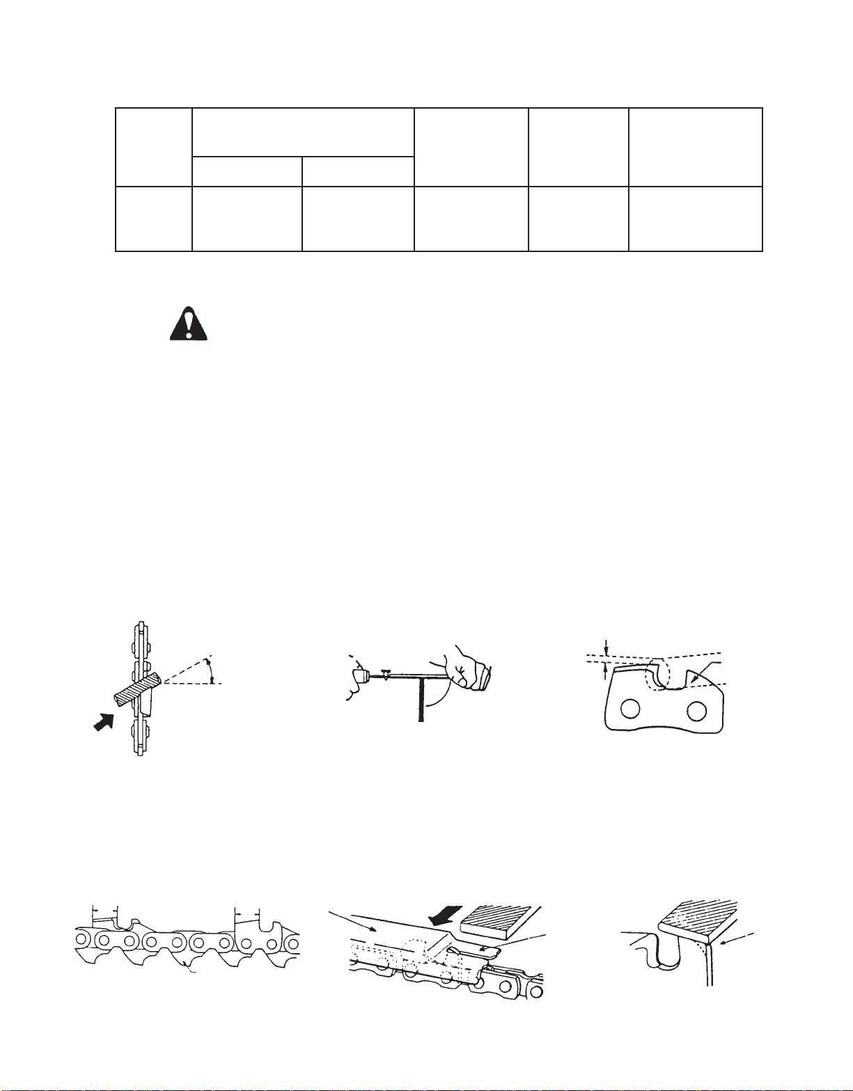
SETTING THE SAW CHAIN
For setting saw chains, round file (4 mmø: 5/32”) and flat file are used.
• T o keep correct position and correct angle, use a file holder .
- Round file and flat file are available from your Echo Dealer.
• File cutters as below.
T o sharpen other types of chains, follow chain manufacturer’s instructions
T ype : 91VG
30°
Keep this angle
PUSH FILE AS SHOWN
• Place the depth gauge tool firmly on guide bar so that depth gauge protrudes. Then file top of depth gauge with flat file
until flat with top of the gauge tool.
- Be sure to round off the front edge of the depth gauge.
Depth gauge
Sharpen bottom
edge
HOLD FILE HOLDER
LEVEL
tool
1/5
ONE FIFTH OF FILE DIAMETER
REMAINS ABOVE CUTTER EDGE
Remove
until flat
with tool
Depth
gauge
Round
off the
edge
17
Page 18
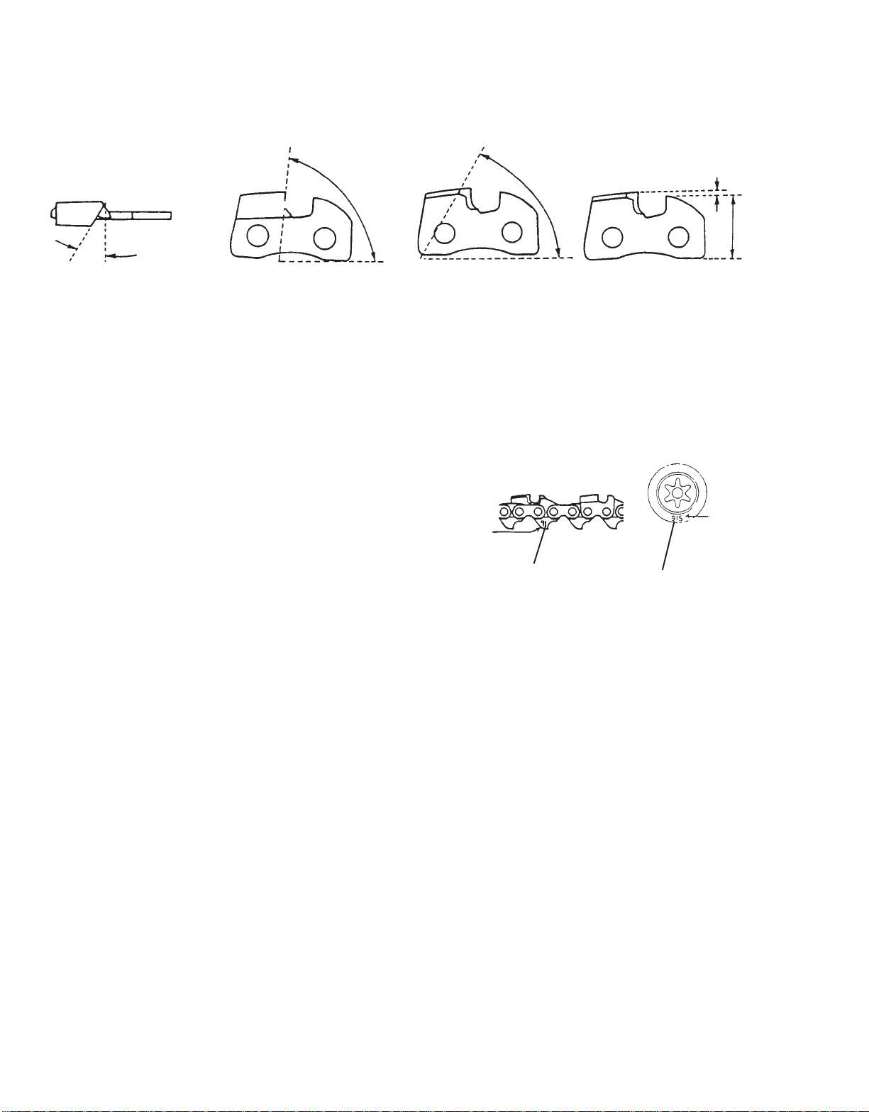
• Properly filed cutters are shown below.
(Top plate angle) (Side plate angle) (Top plate cutting angle) (Depth gauge)
0.64 mm (0.025”)
Parallel
30°
85°
60°
• When setting of the chain is finished, soak it in oil and wash away filings completely before using.
• When chain has been filed on the bar, supply suf ficient oil to it, rot ate the chain slowly to wash away the filings before
using again.
• If the chain saw is operated with filings clogged in the groove, the saw chain and the guide bar will be damaged
prematurely
• If the saw chain becomes soiled with resin, for instance, clean it with kerosene and soak it in oil.
CHAIN TYPE AND SPROCKET PITCH
Saw chain should be used with corresponding pitched
sprocket. To identify chain type and pitch of sprocket,
check as follows.
• Chain type number (A) is stamped on drive link.
• Sprocket pitch (B) is stamped on clutch drum.
Number
indicates Chain
type
(DRIVE LINK)
91
A
(SPROCKET)
91S
Number
indicates
Chain type
B
18
Page 19

TROUBLESHOOTING
Poor performance of the engine and/or cutting mechanism can normally be prevented by carefully following these
instructions.
Poor performance can easily be corrected even by a beginner.
When the engine does not function properly check the following three (3) points first.
• Is the engine compression adequate?
• Is fuel system in good condition and is enough fuel being supplied?
• Is electrical system in good condition and is spark plug operating normally?
When there is serious trouble with the unit, do not try to repair it yourself but have your distributor or dealer do it for you.
For detailed TROUBLESHOOTING refer to tables 1 and 2. Locate the problem on the following charts and repair as
necessary.
Table 1
Engine cranks
There is fuel in the tank
Engine does not start (or, is difficult to start)
Fuel is reaching cylinder
Fuel is reaching carburetor
Fuel is not
reaching carburetor
Fuel is not reaching
cylinder
There is spark at high
tension cord end
○○○○○
○○○○○○
No spark at high tension
cord end.
No spark at plug
Fuel does not
keep running
○○○
○○
○○○
Fuel strainer clogged ...................................Clean.
Fuel pipe clogged ........................................Clean.
Suction insufficient ....................................... Make sufficient.
Strainer clogged .......................................... Clean.
Carburetor out of order ................................. Disassemble and check.
C.D.I. module defective ................................. Remove and replace.
Ignition coil defective .................................... Remove and replace.
Wire connection defective ............................. Reconnect.
High-tension cord connection defective ......... Repair as necessary.
Switch is grounded ....................................... Switch on.
Insulator cracked .......................................... Replace plug.
Spark gap incorrect ...................................... Adjust.
Covered with carbon ..................................... Clean or replace.
Fouled with fuel ............................................ Clean or replace.
Starting procedures incorrect ....................... Start correctly .
Low and high speed needle
setting too lean .............................................Readjust.
Metering lever spring too strong .................. Readjust.
Fuel pump diaphragm defective .....................Replace.
There is spark at plug
Starting procedures
correct
Engine does
not crank
Acceleration
and low speed
function
defective
Carburetor
overflow
○○○○○
19
○○○
○○○
Fuel passage clogged with dust ...................Disassemble and clean.
Fuel leaking from fixing surfaces
of carburetor ................................................ Retighten all screws.
Air valve, fuel tank cap does not
work normally.............................................. Replace or Clean.
Fuel pump does not operate .......................... Check impulse drilling.
Fuel inlet needle valve clogged with dust ....... Clean.
Metering lever spring not placed
in dent of lever .............................................. Correct.
Muffler sticky with fuel ...................................Fuel mixture is too rich
Bearing damaged ......................................... Disassemble and replace.
Piston and/or cylinder seized ........................ Disassemble and replace.
Crankshaft worn ........................................... Disassemble and replace.
Crankshaft contacting crankcase .................. Disassemble and replace.
Start the engine several times
with choke rod fully open and
run at fast idle until engine
does not smoke.
Page 20

Table 2
Engine
overheated
Improper fuel used .......................................Use fuel with correct mixing ratio. Never use
gasoline of poor quality.
Spark plug defective (burnt) .......................... Replace.
As cooling fins clogged, air
does not pass well ........................................Clean fins.
Excessive deposits in
combustion chamber.................................... Disassemble and remove carbon.
Firing function
defective
Carburetor
Ouput (engine speed) insufficient
Engine keeps running, but chain does not cut clean
defective
Other
troubles
Chain does not cut
clean
Chain stops
(Clutch slips)
Plug damaged or fouled ................................ Replace or clean.
Comubstion poor due to
defective wiring ............................................Check wiring.
High-speed needle setting incorrect ..............Readjust.
Carburetor overflow ..................................... Refer to T able 1.
Air cleaner clogged ...................................... Clean as necessary.
Compression insufficient
(piston ring stuck or worn out) ...................... Disassemble, check and replace if necessary.
Cylinder chromium plating peeled ................ Replace cylinder
or worn out
Exhaust port clogged with carbon ................. Clean as necessary.
Throttle is not fully open................................ Readjust.
Chain tension incorrect ................................ Adjust.
Chain wrongly set ........................................ Set correctly.
Depth incorrect ............................................Readjust.
Chain saw pressed against
tree to firmly ................................................Press lightly.
Clutch shoe worn out.................................... Replace.
No oil in tank ................................................ Refill.
Output (engine speed) sufficient
Chain poorly
lubricated
Oil delivery incorrect.................................... Adjust.
Oil contaminated with dust ........................... Rinse tank and fill with new oil..
Oil viscosity inappropriate ............................ Use oil with correct viscosity for summer or winter.
STORAGE AFTER USE
• Inspect and adjust every part of the chain saw.
- Completely clean every part, and repair, if necessary.
- Apply thin coating of oil on metal parts to prevent rust.
- Remove chain and guide bar, apply sufficient oil coating and wrap them up in plastic.
• Drain fuel tank, pull starter slowly a few times to drain fuel from carburetor.
• Pour a small amount of clean two-stroke oil into spark plug hole, pull starter and crank engine until the piston is at TOP
DEAD CENTER.
• Store in a dry area, free from dust.
20
Page 21
CORRECT USE OF CHAIN BRAKE
The installation of a chain brake may be mandatory by law or as stipulated by insurance regulations in your area of
operation. Y ou should enquire through local government offices, your employer or your local dealer to ensure that your
chain saw conforms to the required safety standard. Echo chain brakes have been designed and tested to comply with
international safety standards as follows.
USA: ANSI Standard B175.1-2000 Safety Requirement for chain saws
Canada: CSA Standard Z 62.1 CHAIN SAWS
WARNING :
• ANSI Standard B175.1-2000 stipulates that the brake shall stop the chain in 0.10 seconds (one tenth) at an engine
speed of 8000 RPM. It is the responsibility of the Owner/Operator to ensure that the brake is serviced, adjusted and
tested strictly in accordance with the instructions as detailed herein in order to ensure that the brake performance is
maintained in compliance with the Standard B175.1-2000.
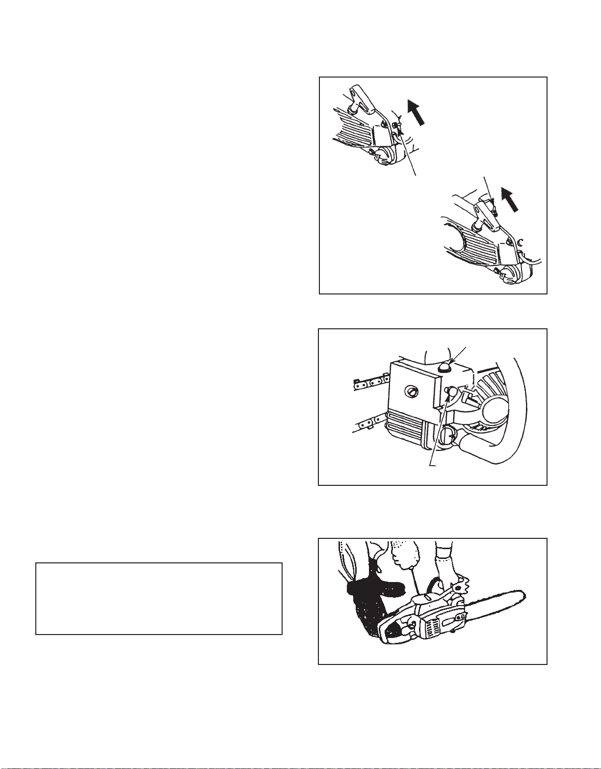
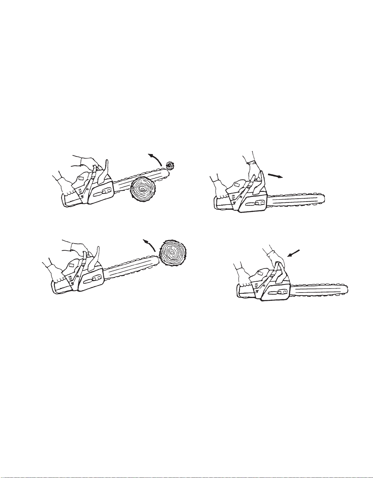
Kickback Motion:
• When the bar nose hits another tree, etc.
• Improper thrust cutting.
Function:
• When the lever is pushed forward, chain brake instantly
works to stop the chain.
Release:
• When the lever is fully pulled toward the operator, brake is
released.
INSTALLATION
• Echo recommends that the chain brake should be
serviced by an authorized Echo servicing dealer.
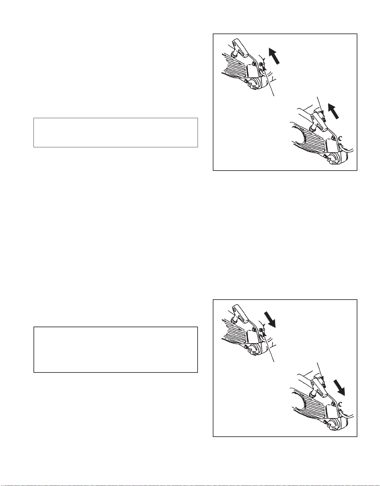
OPERATION
• Set the lever in the released position before starting to cut.
• If the brake is tripped by kick back reaction, the chain will
stop. Immediately release the throttle to avoid possible
damage to the engine or clutch.
• Do not attempt to start or operate the engine with the
brake engaged.
TESTING THE BRAKE
• Start the engine on a solid level surface and run at a fast
idle until warm.
• Hold the saw firmly by the handles and accelerate the
engine to a fast idle.
• Slowly operate the chain brake lever while holding the saw
firmly on the ground. When the brake lever trips, the chain
should stop. Immediately release the throttle trigger.
CAUTION
DO NOT ALLOW THE SA W TO TIP FORW ARD IN ORDER TO
AVOID DAMAGE T O THE CHAIN.
If the chain does not stop, immediately return the saw to your
authorized Echo dealer for repair.
21
Page 22

NOTES
22
Page 23

NOTES
23
Page 24

SERVICING INFORMATION
P ARTS
Genuine ECHO Parts and ECHO REPOWERTM Parts and Assemblies for
your ECHO products are available only from an Authorized ECHO
Dealer. When you do need to buy parts always have the Model
Number, Type number and Serial Number of the unit with you. You can
find all three numbers on the engine housing. For future reference, write
them in the space provided below.
Model No. _____________Type No. ____________ SN. __________
SERVICE
Service of this product during the warranty period must be performed
by an Authorized ECHO Service Dealer. For the name and address of
the Authorized ECHO Service Dealer nearest you, ask your retailer or
call: 1-800-432-ECHO. When presenting your unit for Warranty
service/repairs, proof of purchase is required.
DEALER?
Call
1-800-432-ECHO
or
www.echo-usa.com
ECHO CONSUMER PRODUCT SUPPORT
If you require assistance or have questions concerning the application,
operation or maintenance of this product you may call the ECHO
Consumer Product Support Department at 1-800-673-1558 from 8:30 am
to 4:30 pm (Central Standard Time) Monday through Friday. Before
calling, please know the model and serial number of your unit to help
your Consumer Product Support Representative.
W ARRANTY CARD
This card is our means of registering all original owners of ECHO
equipment. The card plus proof of purchase provides you the assurance that authorized warranty work will be done. It also provides a
direct link between you and ECHO if we find it necessary to contact
you.
ADDITIONAL OR REPLACEMENT MANUALS
Safety Manuals in English/Spanish or English/French are available, free of charge, from your ECHO dealer or at
www.echo-usa.com.
Instruction and Parts Manuals are available by:
• Downloading free from www.echo-usa.com
• Purchasing from your Echo Dealer.
• Sending a check or money order for $2.00 per Parts Catalog or $1.50 per Instruction Manual made payable to ECHO,
INCORPORATED. State on a sheet of paper the model number and serial number of the ECHO unit you have, part
number of the manual (if known), your name and address and mail to address above.
Safety Videos are available from your Echo dealer. A $5.00 shipping charge will be required for each video.
CONSUMER PRODUCT
SUPPORT
1-800-673-1558
8:30 - 4:30 Mon - Fri C.S.T.
Available Parts Lists
CS-3000 TYPE 1E S/N 001001 & UP PART NUMBER 99922203113
CS-3400 TYPE 1E S/N 001001 & UP PART NUMBER 99922203114
CS-3450 TYPE 1E S/N 001001 & UP PART NUMBER 99922203115
ECHO, INCORPORATED
400 OAKWOOD ROAD
LAKE ZURICH, IL 60047
www.echo-usa.com
 Loading...