

Page 1
OWNER'S
®
MANUAL
12 INCH CHIPPER
7812086 - 86 HP
PN: 18130-00 R040306
Companion to 18131-00
Effective serial number: 506431
RECORD SERIAL NUMBER HERE
Page 2
BEFORE YOU BEGIN
MANUFACTURED BY CRARY COMPANY
MANUFACTURED IN U.S.A.
XXXXXX
A DIVISION OF TERRAMARC INDUSTRIES
WEST FARGO, NORTH DAKOTA 58078 U.S.A.
SERIAL NUMBER
DEAR BEAR CAT CUSTOMER,
Thank you for purchasing a Bear Cat product. The Bear Cat line is designed, tested, and
manufactured to give years of dependable performance. To keep your machine operating at peak
efficiency, it is necessary to adjust it correctly and make regular inspections. The following pages
will assist you in the operation and maintenance of your machine. Please read and understand
this manual before operating.
If you have any questions or comments about this manual, please call us toll-free at 1-800-247-
7335.
If you have any questions or problems with your machine, please call or write your local factory-
authorized Bear Cat dealer.
This document is based on information available at the time of its publication. Bear Cat is continually
making improvements and developing new equipment. In doing so, we reserve the right to make
changes or add improvements to our product without obligation for equipment previously sold.
PLEASE SEND US YOUR WARRANTY CARD
A warranty card is included in your owner's kit packaged with your machine. Please take the time
to fill in the information requested on the card. When you send your completed card to us, we will
register your machine and start your coverage under our limited warranty.
SERIAL NUMBER LOCATION
Always give your authorized Bear Cat dealer the serial number of your Bear Cat product when
ordering parts, requesting service or any other information.
Please record the serial number in the space provided on the front cover and on the warranty and
registration card.
How to Contact
Bear Cat
ADDRESS
Bear Cat
237 NW 12th Street
PO Box 849
West Fargo, ND 58078
PHONE
800-247-7335
701-282-5520
Fax: 701-282-9522
E-MAIL
opesales@crary.com
service@crary.com
HOURS
M-F, 8 a.m. to 5 p.m.
Central Time
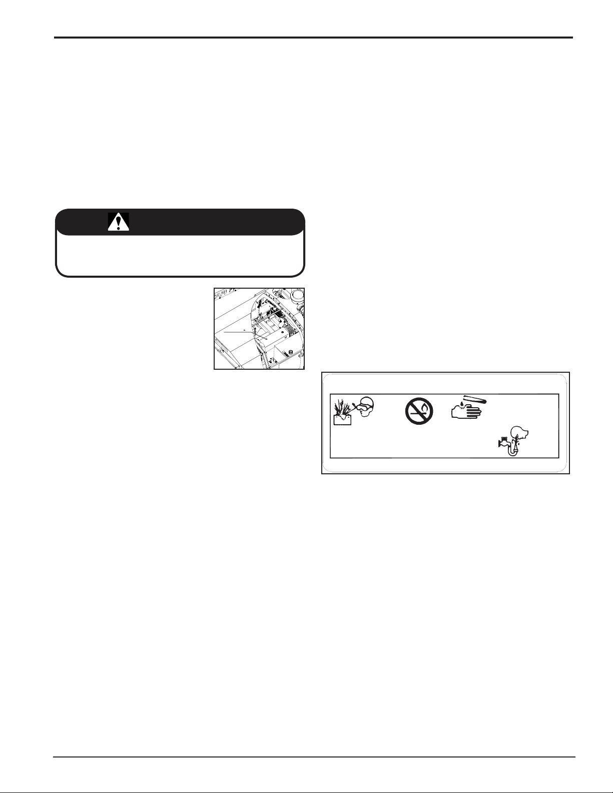
SERIAL NUMBER DECAL LOCATION
© 2006, Crary Company, All rights reserved. Produced and printed in the USA.
Serial Number Decal
Page 3

LIMITED WARRANTY
This warranty applies to Bear Cat, Crary, Load-N-Lift, Lockwood and Weed Roller brand products manufactured
by Crary Company, a division of TerraMarc Industries, henceforth called Crary Company.
Crary Company warrants to the original owner each new Crary Company product to be free from defects
in material and workmanship, under normal use and service. The warranty shall extend 1 year from date of
delivery for income producing (commercial) applications and 2 years from date of delivery for non-income
producing (consumer) use of the product. The product is warranted to the original owner as evidenced by a
completed warranty registration on file at Crary Company. Replacement parts are warranted for (90) days
from date of installation.
THE WARRANTY REGISTRATION MUST BE COMPLETED AND RETURNED TO CRARY COMPANY
WITHIN 10 DAYS OF DELIVERY OF THE PRODUCT TO THE ORIGINAL OWNER OR THE WARRANTY
WILL BE VOID.
In the event of a failure, return the product, at your cost, along with proof of purchase to the selling Crary
Company dealer. Crary Company will, at its option, repair or replace any parts found to be defective in material
or workmanship. Warranty on any repairs will not extend beyond the product warranty. Repair or attempted
repair by anyone other than a Crary Company dealer as well as subsequent failure or damage that may occur
as a result of that work will not be paid under this warranty. Crary Company does not warrant replacement
components not manufactured or sold by Crary Company.
This warranty applies only to parts or components that are defective in material or workmanship.
1.
This warranty does not cover normal wear items including but not limited to bearings, belts, pulleys, filters
2.
and chipper knives.
This warranty does not cover normal maintenance, service or adjustments.
3.
This warranty does not cover depreciation or damage due to misuse, negligence, accident or improper
4.
maintenance.
This warranty does not cover damage due to improper setup, installation or adjustment.
5.
This warranty does not cover damage due to unauthorized modifications of the product.
6.
Engines are warranted by the respective engine manufacturer and are not covered by this warranty.
7.
Crary Company is not liable for any property damage, personal injury or death resulting from the unauthorized
modification or alteration of a Crary product or from the owner’s failure to assemble, install, maintain or operate
the product in accordance with the provisions of the Owner’s manual.
Crary Company is not liable for indirect, incidental or consequential damages or injuries including but not
limited to loss of crops, loss of profits, rental of substitute equipment or other commercial loss.
This warranty gives you specific legal rights. You may have other rights that may vary from area to area.
Crary Company makes no warranties, representations or promises, expressed or implied as to the performance
of its products other than those set forth in this warranty. Neither the dealer nor any other person has any
authority to make any representations, warranties or promises on behalf of Crary Company or to modify the
terms or limitations of this warranty in any way. Crary Company, at its discretion, may periodically offer limited,
written enhancements to this warranty.
CRARY COMPANY RESERVES THE RIGHT TO CHANGE THE DESIGN AND/OR SPECIFICATIONS
OF ITS PRODUCTS AT ANY TIME WITHOUT OBLIGATION TO PREVIOUS PURCHASERS OF ITS
PRODUCTS.
Bear Cat Owners Manual
i
Page 4

TABLE OF CONTENTS
DESCRIPTION PAGE DESCRIPTION PAGE
SAFETY .......................................................................1
1.1 THE SAFETY ALERT SYMBOL ...........................................1
1.2 EMISSION INFORMATION ..................................................1
1.3 BEFORE OPERATING .........................................................1
1.4 OPERATION SAFETY ..........................................................2
1.5 FEED ROLLER SAFETY .....................................................2
1.6 MAINTENANCE AND STORAGE SAFETY .........................2
1.7 DRIVELINE SAFETY ...........................................................3
1.8 TOWING SAFETY ................................................................3
1.9 BATTERY SAFETY ..............................................................3
1.10 SAFETY DECALS ..............................................................4
1.11 SAFETY DECALS ..............................................................5
ASSEMBLY .................................................................6
2.1 CONNECTING THE BATTERY ............................................6
2.2 CHECKING/ADDING HYDRAULIC FLUID ...........................6
2.3 CHECKING/ADDING MOTOR OIL TO ENGINE ..................6
2.4 CHECKING/ADDING COOLANT ..........................................6
2.5 FILLING THE TANK .............................................................6
FEATURES & CONTROLS .........................................7
3.1 KEY SWITCH .......................................................................9
3.2 ENGINE THROTTLE ............................................................9
3.3 MURPHY SWITCH ...............................................................9
3.4 RESET BUTTON ..................................................................9
3.5 FUEL GAUGE ......................................................................9
3.6 TEMPERATURE GAUGE .....................................................9
3.7 GLOW LAMP ........................................................................9
3.8 OIL PRESSURE GAUGE .....................................................9
3.9 CHARGE LAMP ...................................................................9
3.10 HYDRAULIC OIL RESERVOIR ..........................................9
3.11 COOLANT RESERVE TANK ..............................................9
3.12 ENGAGEMENT HANDLE ..................................................9
3.13 DISCHARGE CHUTE .........................................................9
3.14 DISCHARGE CAP ..............................................................9
3.15 FEED ROLLER LIFT CONTROL ........................................9
3.16 FEED ROLLER CONTROL BAR ........................................9
3.17 FEED ROLLER SPEED CONTROL ...................................9
3.18 HITCH JACK ......................................................................9
3.19 ROTOR COVER HYDRAULIC JACK .................................9
OPERATION .............................................................10
4.1 STARTING DIESEL MODELS ............................................10
4.2 STOPPING THE CHIPPER ................................................10
4.3 DIRECTING THE DISCHARGE CHUTE ............................10
4.4 RAISE/LOWER THE ROTOR COVER ...............................11
4.5 FEED ROLLER CONTROL BAR ........................................11
4.6 FEED ROLLER SPEED CONTROL ................................... 11
4.7 FEED ROLLER LIFT CONTROL ........................................11
4.8 CHIPPER FEED CONTROLLER .......................................12
4.9 CHIPPING GUIDE ..............................................................12
SERVICE & MAINTENANCE ....................................13
5.1 MAINTENANCE SCHEDULE .............................................13
5.2 CHIPPER BLADES ............................................................14
5.2.1 REMOVING THE BLADES .....................................14
5.2.2 SHARPENING THE BLADES ................................. 14
5.2.3 INSTALLING THE BLADES .................................... 14
5.3 SETTING CHIPPING BLADE CLEARANCE .......................15
5.4 REPLACING THE DRIVE BELT .........................................15
5.5 CHECKING/ADDING COOLANT .......................................15
5.6 REPLACE/CLEAN THE AIR FILTER ..................................16
5.7 HYDRAULIC FLUID RESERVOIR .....................................16
5.8 CHANGING THE HYDRAULIC OIL FILTER ......................16
5.9 TRAILER SERVICE TIPS ...................................................16
5.10 GREASING BEARINGS ...................................................16
TROUBLESHOOTING ..............................................18
SPECIFICATIONS .....................................................19
7.1 BOLT TORQUE ..................................................................19
7.2 KUBOTA ENGINE SAFETY SHUTDOWN
AUX. CIRCUIT. ...................................................................20
7.3 KUBOTA ENGINE SCHEMATIC ........................................21
ii
Bear Cat Owners Manual
Page 5
#
1
Section
Safety
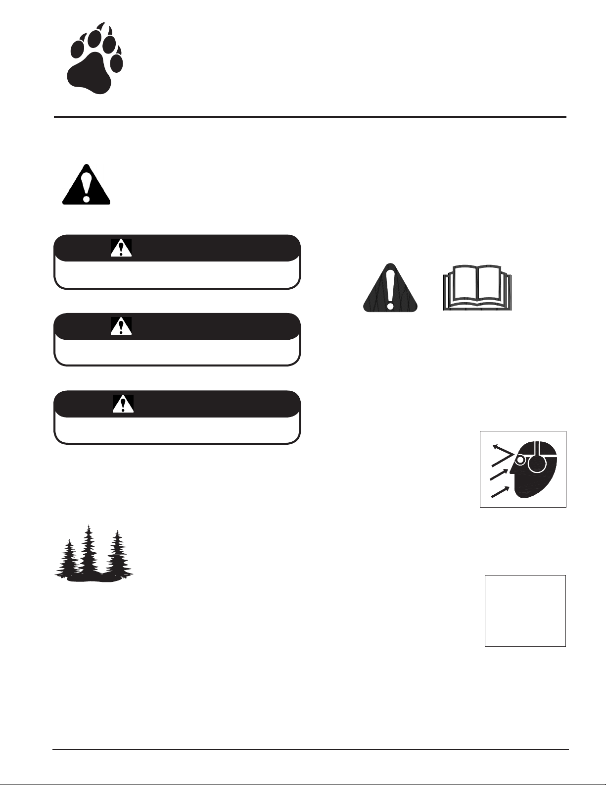
1.1 THE SAFETY ALERT SYMBOL
The Owner/Operators manual uses this symbol
to alert you of potential hazards. Whenever
you see this symbol, read and obey the safety
message that follows it. Failure to obey the
safety message could result in personal injury,
death or property damage.
DANGER
Indicates an imminently hazardous situation that, if not
avoided, will result in death or serious injury.
WARNING
Indicates a potentially hazardous situation that, if not avoided,
could result in death or serious injury.
CAUTION
Indicates a potentially hazardous situation that, if not avoided,
may result in minor or moderate injury.
1.2 EMISSION INFORMATION
WARNING TO ALL CALIFORNIA AND OTHER STATES
OPERATING OUTDOOR POWER EQUIPMENT
Under California Law and under the laws of
several other states, you are not permitted
to operate an internal combustion engine
using hydrocarbon fuels on any forest
covered, brush covered or grass covered
land or on land covered with grain, hay
or other flammable agricultural crops, without an engine spark
arrester in continuous effective working order.
The engine on your power equipment, like most outdoor power
equipment, is an internal combustion engine that burns gasoline
(a hydrocarbon fuel). Therefore, your power equipment must be
equipped with a spark arrester muffler in continuous effective
working order. The spark arrester must be attached to the engine
exhaust system in such a manner that flames or heat from the
system will not ignite flammable material.
Failure of the owner/operator of the equipment to comply with
this regulation is a misdemeanor under California law and may
also be a violation of other state and/or federal regulations, laws,
ordinances, or codes. Contact your local fire marshal or forest
service for specific information about which regulations apply
in your area.
The standard muffler installed on the engine is not equipped
with a spark arrester. One must be added before using this
machine in an area where a spark arrester is required by law.
Contact the local authorities if these laws apply to you. See your
authorized engine dealer for spark arrester options.
1.3 BEFORE OPERATING
Read and understand this Owner/Operators manual. Be
1.
completely familiar with the controls and the proper use of
this equipment.
2.
Familiarize yourself with all of the safety and operating
decals on this equipment and on any of its attachments or
accessories.
3.
Keep safety decals clean and legible. Replace missing or
illegible safety decals.
4.
Obtain and wear safety glasses and
use hearing protection at all times
when operating this machine.
5.
Avoid wearing loose fitted clothing.
Never operate this machine wear
ing clothing with drawstrings that
could wrap around or get caught
in the machine.
6.
Do not operate this machine if you are under the influence of
alcohol, medications, or substances that can affect your vi
sion, balance or judgement. Do not operate if tired or ill. You
must be in good health to operate this machine safely.
7.
Do not operate this equipment in
the vicinity of bystanders. Keep the
area of operation clear of all persons,
particularly small children. It is rec
ommended that bystanders keep at
least 50 feet (15 meters) away from
the area of operation.
Do not allow children to operate this equipment.
8.
Use only in daylight or good artificial light.
9.
10.
Do not run this equipment in an enclosed area. Engine ex
haust contains carbon monoxide gas, a deadly poison that is
odorless, colorless and tasteless. Do not operate this equipment in or near buildings, windows or air conditioners.
-
-
-
-
Bear Cat Owners Manual
1
Page 6
SAFETY
WRONG
WRONG
Always use an approved fuel container. Do not remove gas
11.
cap or add fuel when engine is running. Add fuel to a cool
engine only.
12.
Do not fill fuel tank indoors. Keep open flames, sparks,
smoking materials and other sources of combustion away
from fuel.
13.
Do not operate machine without shields in
place. Failure to do so may cause serious
injury or death.
14.
Keep all guards, deflectors, and shields in
good working condition.
15.
Before inspecting or servicing any part
of this machine, shut off power source,
remove key, disconnect the battery cables
and make sure all moving parts have
come to a complete stop.
16.
Check that all screws, nuts, bolts, and
other fasteners are secured, tightened
and in proper working condition before
starting the machine and once every 8
hours of operation.
17.
Do not transport or move machine while
the machine is operating or running.
Ensure debris does not blow into traffic, parked cars, or
9.
pedestrians.
10.
Keep the machine clear of debris and other accumula
tions.
11.
Do not allow processed material to build up in the discharge
area. This may prevent proper discharge and can result in
kickback of material through the feed opening.
12.
Shut off machine immediately if the machine
becomes clogged, the cutting mechanism
strikes any foreign object, or the machine
starts vibrating or making an unusual noise.
Shut off power source, remove key, discon
nect the battery cables and make sure all
moving parts have come to a complete
stop. After machine stops:
Inspect for damage.
A.
Replace or repair any damaged parts.
B.
Check for and tighten any loose parts.
C.
14.
Check blade bolts for proper torque after every 8 hours of
operation. Check blades and rotate or resharpen daily or as
required to keep blades sharp. Failure to do so may cause
poor performance, damage or personal injury and will void
the machine warranty.
-
-
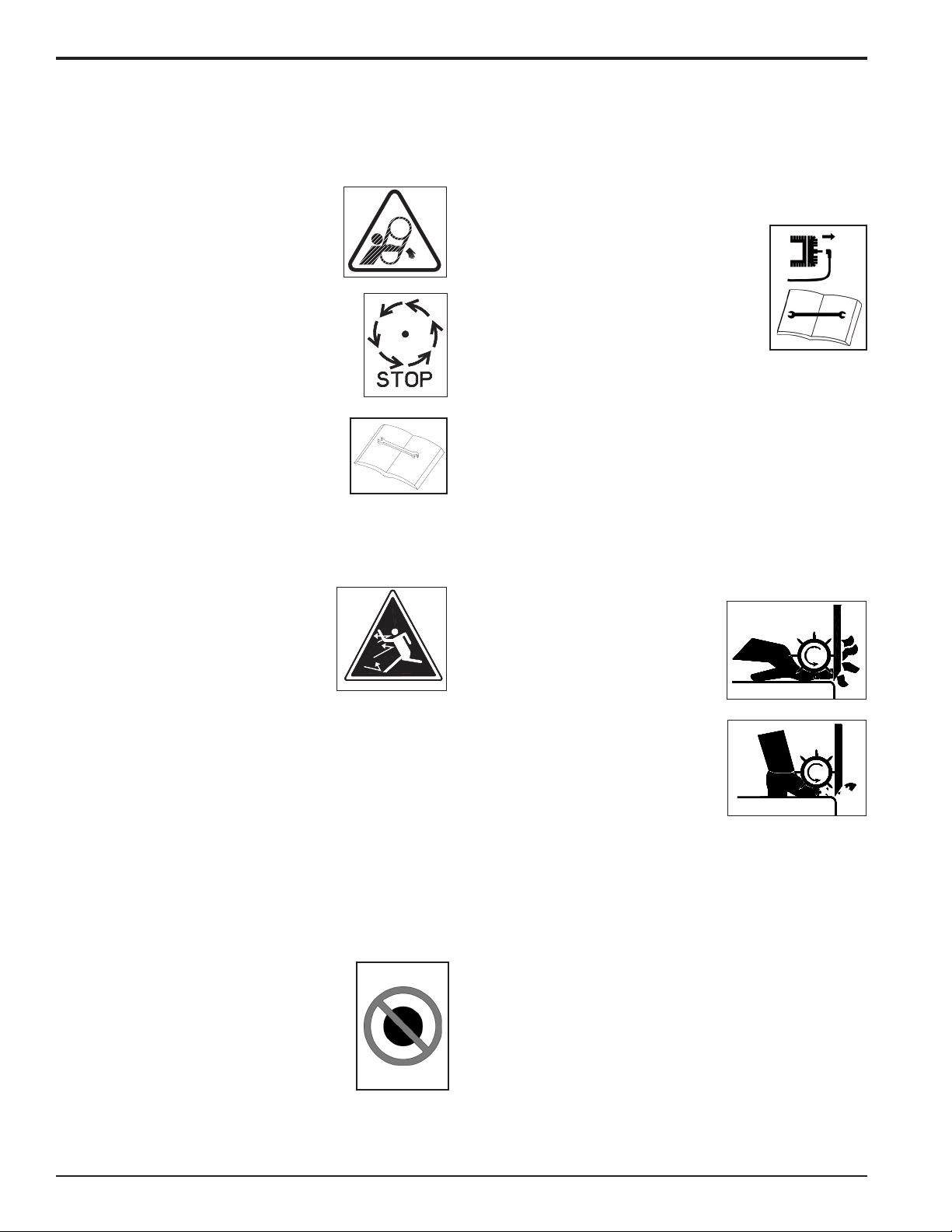
1.4 OPERATION SAFETY
Always stand clear of discharge area
1.
when operating this machine. Keep face
and body away from feed and discharge
openings.
2.
Keep hands and feet out of feed and
discharge openings while machine is
operating to avoid serious personal injury. Stop and al
low machine to come to a complete stop before clearing
obstructions.
3.
Set up your work site so you are not endangering traffic and
the public. Take great care to provide adequate warnings.
4.
Do not climb on machine when operating. Keep proper bal
ance and footing at all times.
5.
Check cutting chamber to verify it is empty before starting
the machine.
6.
Raise engagement lever slowly to engage machine. Lower
engagement lever to disengage machine. The chipper rotor
will continue to rotate when engagement lever is disengaged.
Shut off power source, remove key, disconnect the battery
cables and make sure all moving parts have
come to a complete stop. Do not operate
without all shields in place.
7.
Do not insert branches larger than 12
inches in diameter into chipper or machine
damage may occur.
8.
When feeding material into machine, do
not allow metal, rocks, bottles, cans or any
other foreign material to be fed into chipper.
12 INCH
305 mm
1.5 FEED ROLLER SAFETY
The feed roller can cause serious
1.
injury or death. Keep hands, feet
and clothing away from the feed
roller chipper blades.
2.
Never climb onto the feed chute
-
-
when the unit is operating or run
ning.
3.
Do not overreach. Keep proper
balance and footing at all times.
4.
Never allow passengers to ride on
the feed chute.
When feeding material into the feed roller:
5.
A.
Wear eye, face and hearing protection.
Release material and stand to side of feed chute.
B.
6.
When inspecting or servicing the feed roller, secure the feed
roller in the raised position using the lock-up pin located on
the roller slide (Figure 4.5).
-
1. 6 M AI NTENA NC E A ND S TO RA GE
SAFETY
Before inspecting, servicing, storing, or changing an acces-
1.
sory, shut off power source, disconnect the battery cables
and make sure all moving parts have come to a complete
stop.
2.
Replace any missing or unreadable safety decals. Refer
to the parts manual for part numbers when ordering safety
decals from an area Bear Cat dealer.
2
Bear Cat Owners Manual
Page 7
DANGER / POISON
SHIELD EYES
EXPLOSIVE GASES
CAN CAUSE
BLINDNESS OR
INJURY
NO
• SPARKS
• FLAMES
• SMOKING
SULFURIC
ACID
CAN CAUSE
BLINDNESS OR
SEVERE BURNS
FLUSH EYES
IMMEDIATELY
WITH WATER
GET
MEDICAL
HELP
FAST
KEEP OUT OF THE REACH OF CHILDREN. DO NOT TIP. KEEP VENT CAPS TIGHT AND LEVEL.
Driveline
Shield
Allow machine to cool before storing in an enclosure.
3.
4.
Store the machine out of reach of children and where fuel
vapors will not reach an open flame or spark.
5.
Never store this machine with fuel in the fuel tank inside a
building where fumes may be ignited by an open flame or
spark. Ignition sources can be hot water and space heaters,
furnaces, clothes dryers, stoves, electric motors, etc.
6.
Drain the fuel and dispose of it in a safe manner for storage
periods of three months or more.
1.7 DRIVELINE SAFETY
DANGER
Keep all guards and shields in place at all times while
operating. Failure to do so can result in serious injury or
death.
Shut off power source, disconnect
1.
the battery cables and make sure
all moving parts have come to a
complete stop before removing
guards or shields.
2.
Stay alert and pay attention when
the driveline is operating.
3.
Keep bystanders, especially chil
-
dren, away from the driveline.
4.
Check the driveline to ensure it is securely attached before
operating machine.
5.
Clothing worn by the operator must be fairly tight. Never wear
loose fitted jackets, shirts, or pants when working around the
driveline. Tie long hair back or put under a cap.
6.
Keep hydraulic hoses, electrical cords, chains and other
items from contacting the driveline.
7.
Before inspecting or servicing the driveline area, shut off
power source, remove key, disconnect the battery cables
and make sure all moving parts have come to a complete
stop.
8.
Keep hands, feet and clothing away from all driveline
parts.
9.
Do not clean, lubricate or adjust the driveline when it is
running.
1.8 TOWING SAFETY
Towing laws may vary in different countries/regions/states.
1.
It is recommended that you contact your local motor vehicle
department for any special rules that pertain to towing and
to know the rules of any country/region/state you may travel
through.
2.
Connect hitch safety chains. Tighten and secure trailer
hitch bolts. Do not attempt to tow the trailer if vehicle is not
equipped with the proper size ball or pintle hitch.
3.
Check wheel lug bolts periodically to ensure they are tight
and secure.
Bear Cat Owners Manual
SAFETY
Place the jack stand on the trailer in the UP position to clear
4.
the ground while towing. Place the jack stand on a level
surface and secure it in the DOWN position before using.
5.
Never allow passengers to ride on the chipper.
6.
If applicable, shut off fuel supply when towing.
1.9 BATTERY SAFETY
Improper use and care of the battery on electric start models
can result in serious personal injury or property damage. Always
observe the following safety precautions.
Danger / Poison - Causes Severe Burns. The battery con-
1.
tains sulfuric acid. Avoid contact with skin, eyes or clothing.
Keep out of reach of children.
ANTIDOTE-External Contact: Flush immediately with lots
of water.
ANTIDOTE-Internal: Drink large quantities of water or milk.
Follow with milk of magnesia, beaten egg or vegetable oil.
Call a physician immediately.
ANTIDOTE-Eye Contact: Flush with water for 15 minutes.
Get prompt medical attention.
2.
The battery produces explosive gases. Keep sparks, flame
or cigarettes away. Ventilate area when charging battery.
Always wear safety goggles when working near battery.
3.
The battery contains toxic materials. Do not damage bat
tery case. If case is broken or damaged, avoid contact with
battery contents.
4.
Neutralize acid spills with a baking soda and water solu
tion.
5.
Properly dispose of a damaged or worn-out battery. Check
with local authorities for proper disposal methods.
6.
Do not short circuit battery. Severe fumes and fire can
result.
7.
Before working with electrical wires or components, dis
connect the negative (-) cable first. Disconnect the positive
(+) cable second. Reverse this order when reconnecting
battery cables.
-
-
-
3
Page 8
SAFETY
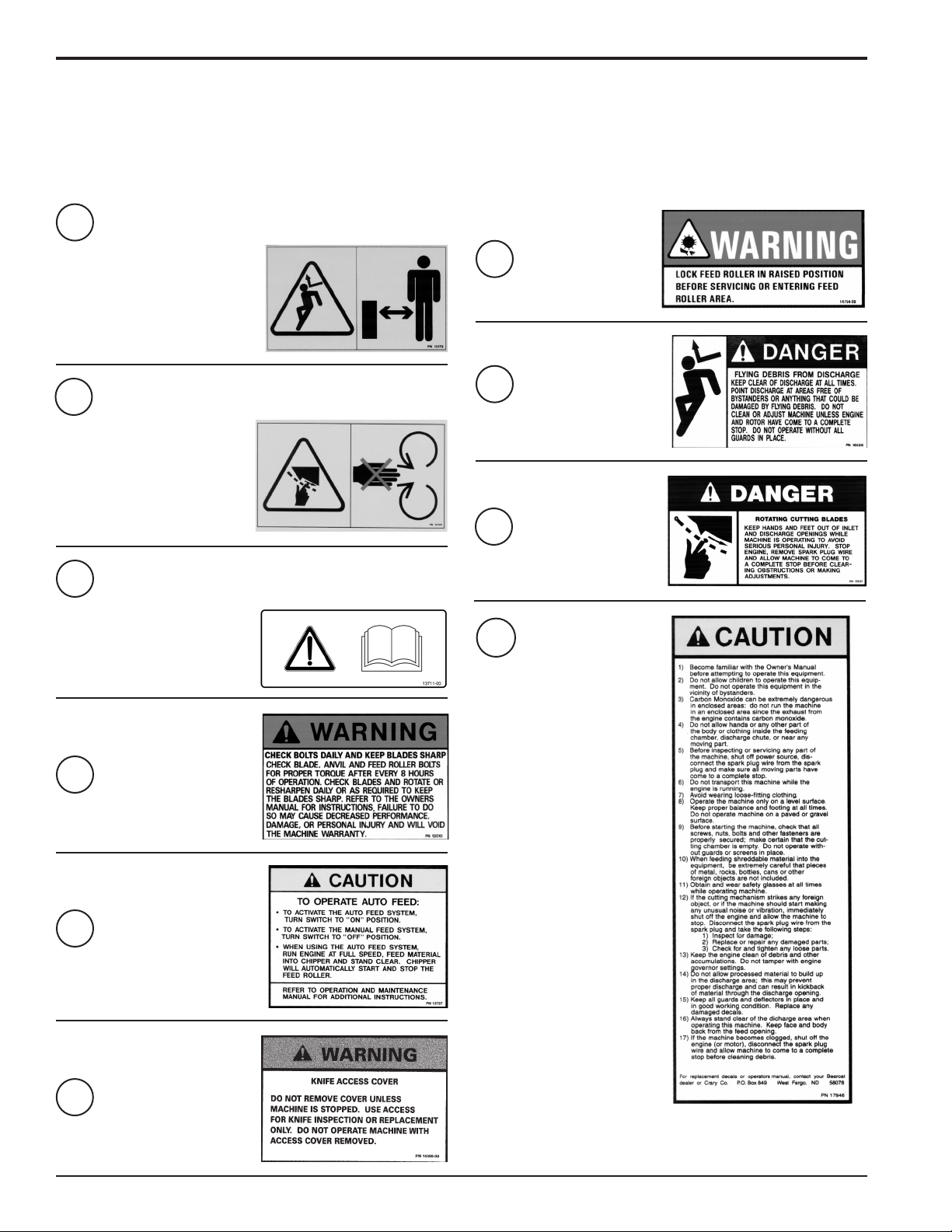
1.10 SAFETY DECALS
Familiarize yourself with all of the safety and operating decals on the machine and the associated hazards. See the engine owners
manual or contact the engine manufacturer for engine safety instructions and decals. Make certain that all safety and operational
decals on this machine are kept clean and in good condition. The decals are shown below at reduced sizes. Refer to the parts catalog
if you need a replacement decal. Decals that need replacement must be applied to their original locations.
PN 12173
1
DO NOT OPERATE THIS EQUIPMENT
IN THE VICINITY OF BYSTANDERS.
DO NOT ALLOW CHILDREN TO
OPERATE THIS EQUIPMENT. ALWAYS
STAND CLEAR OF DISCHARGE AREA
WHEN OPERATING THIS MACHINE.
KEEP FACE AND BODY AWAY FROM
DISCHARGE AREAS.
PN 12175
2
KEEP HANDS AND FEET OUT
OF INLET AND DISCHARGE
OPENINGS WHILE MACHINE IS
OPERATING TO AVOID SERIOUS
PERSONAL INJURY. STOP AND
ALLOW MACHINE TO COME TO
A COMPLETE STOP BEFORE
CLEARING OBSTRUCTIONS.
PN 13711-00
3
READ AND UNDERSTAND THIS
OWNER/OPERATORS MANUAL.
BE COMPLETELY FAMILIAR
WITH THE CONTROLS AND THE
PROPER USE OF THIS
EQUIPMENT.
7
8
9
10
PN 14754-00
PN 16558
PN 17837
PN 17846
PN 12010
4
PN 12737
5
PN 14369-00
6
4
Bear Cat Owners Manual
Page 9
SAFETY
1.11 SAFETY DECALS
The numbers below correspond to the decals in Section 1.10. Familiarize yourself with all of the safety and operational decals on
the machine and the associated hazards. See the engine owners manual or contact the engine manufacturer for engine safety
instructions and decals. Make certain that all safety and operational decals on this machine are kept clean and in good condition. The
decals are shown below at reduced sizes. Refer to the parts catalog if you need a replacement decal. Decals that need replacement
must be applied to their original locations.
1
8
7
3
1
8
9
2
9
2
7
Bear Cat Owners Manual
5
4
10
6
5
Page 10

#
2
Assembly
Section
WARNING
Before inspecting or servicing any part of this machine, shut
off power source, remove key, disconnect the battery cables
and make sure all moving parts have come to a complete
stop.
IMPORTANT
If any bolts or nuts are dropped in the machine, be sure to
remove them before starting the machine.
2.1 CONNECTING THE BATTERY
A battery ships with the chipper. If the battery is not connected,
refer to the battery owners manual for instructions on connecting
the battery and for service and maintenance information.
WARNING
To avoid sparks and a possible explosion or fire due to a short
circuit, do not touch the positive (+) battery terminal and any
surrounding metal with tools, jewelry or other metal objects.
When installing battery cables, connect the positive (+) cable
first and the negative (-) cable last.
will drop and bubbles may appear in the fluid. Refill the
reservoir as necessary.
Run the feed roller in both directions for several minutes until
6.
any remaining air purges from the unit. Refill the reservoir
as necessary.
7.
Shut down the engine, check for and correct any fluid leaks,
and check the reservoir level. Add fluid if necessary. The
hydraulic gear pump is now ready for operation.
2.3 CHECKING/ADDING MOTOR OIL TO
ENGINE
Check the oil level and, if needed, fill the engine crankcase
with the type and amount of oil specified in the engine owners
manual.
2.4 CHECKING/ADDING COOLANT
The diesel engine is tested before shipping. In order to test the
equipment, the fluid levels are filled. However, before starting
the machine, check the coolant level in the radiator and coolant
reserve tank (if equipped) to ensure it is with in the proper
operating range (between FULL and FILL). Refer to the engine
owner's manual for specific instructions on checking and adding
coolant.
2.5 FILLING THE TANK
2.2 CHECKING/ADDING HYDRAULIC FLUID
Hydraulic fluid drives the feed roller. The hydraulic pump is
attached to the motor or connected to the motor with a belt.
The hydraulic pump requires premium hydraulic fluids containing
high quality rust, oxidation, and foam inhibitors. These include
premium turbine oils, API CD engine oils per SAE J183,
M2C33F or G automatic transmission fluids meeting Allison C3 or Caterpillar TO-2, and certain specialty agricultural tractor
fluids.
If system has no oil, follow this startup procedure:
Clean all system components (reservoir, fittings, etc.) before
1.
starting the hydraulic pump.
2.
After filtering the hydraulic fluid, fill the hydraulic reservoir.
3.
Fill the inlet line leading from the reservoir to the pump
before start-up. Loosen the fitting at the pump on this inlet
line until oil bleeds out.
Start the engine and run at the lowest possible RPM.
4.
5.
As you purge air from the unit, the oil level in the reservoir
6
Bear Cat Owners Manual
DANGER
Fuel is highly flammable and its vapors are explosive. To prevent personal injury or property
damage:
Store fuel only in approved containers, in well
ventilated, unoccupied buildings, away from
sparks or flames. Do not fill the fuel tank while the engine is
hot or running. Spilled fuel could ignite if it comes in contact
with hot parts. Do not start the engine near spilled fuel. Never
use fuel as a cleaning agent.
For best results use only clean, fresh, fuel. Purchase fuel in small
quantities and store in clean, approved containers. Do not mix
gasoline or alcohol with diesel fuel.
REFER TO THE ENGINE OWNERS MANUAL FOR FURTHER
FILLING INSTRUCTIONS.
IMPORTANT
Do not attempt to start the engine at this time. Wait until you
have read the complete starting instructions in the Operation
Section of this manual.
Page 11

#
3
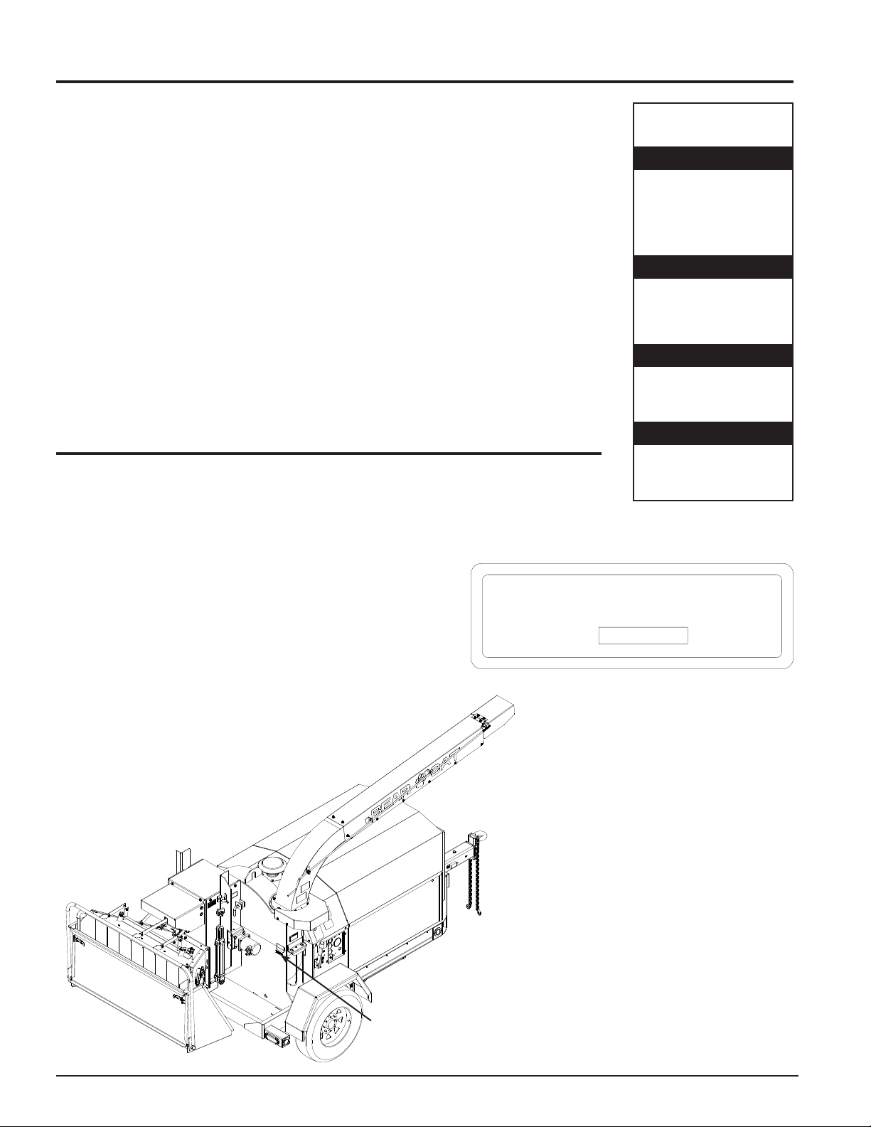
Features & Controls
Section
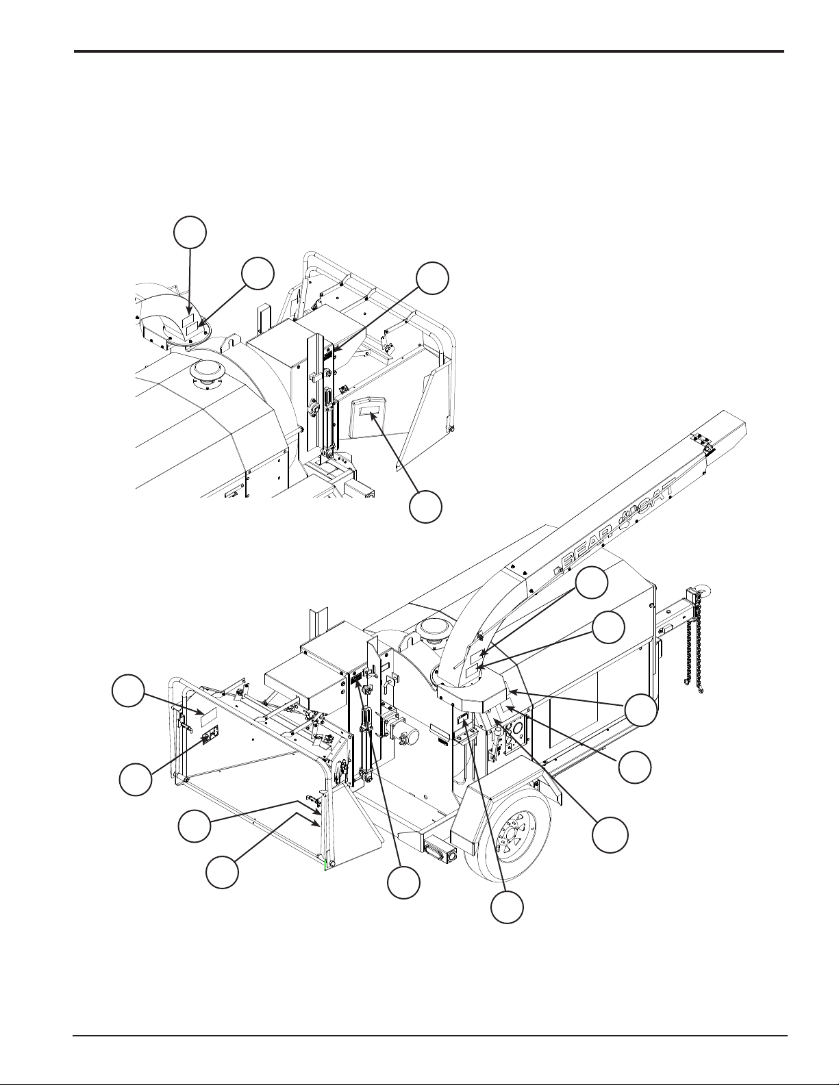
Understanding how your machine works will help you achieve the best results when using your chipper. The following descriptions
define the features and controls of your machine.
REFER TO ENGINE OWNERS MANUAL FOR FURTHER ENGINE OPERATING INSTRUCTIONS.
DISCHARGE CAP
FEED ROLLER
LOCKUP PIN
ROTOR COVER
LOCKUP PIN
DISCHARGE TUBE
FEED ROLLER
HYDRAULIC LIFT
HITCH
CONTROL PANEL
ENGAGEMENT HANDLE
FEED ROLLER
CONTROL BAR
ROTOR COVER
HOOD LATCH
HITCH JACK
Bear Cat Owners Manual
7
Page 12

FEATURES & CONTROLS
FUEL GAUGE
TEMPERATURE
GAUGE
OIL PRESSURE
GAUGE
THROTTLE
Figure 3.2 - Control Panel w/Murphy Switch
GLOW LAMP
MURPHY SWITCH
CHARGE LAMP
Serial Number 506430 and Below.
Figure 3.1 - Feed Roller Controls
FUEL GAUGE
TACHOMETER
KEY SWITCH
TEMPERATURE
GAUGE
OIL PRESSURE
GAUGE
THROTTLE
GLOW LAMP
RESET BUTTON
CHARGE LAMP
TACHOMETER
KEY SWITCH
Figure 3.3 - Control Panel w/Reset Button
Serial Number 506431 and Above.
8
Bear Cat Owners Manual
Page 13

FEATURES & CONTROLS
3.1 KEY SWITCH
The control panel houses the key switch. Turn the key to the right
to start the machine. On diesel models, turning the key to the left
preheats the glow plug.
3.2 ENGINE THROTTLE
This controls the speed of the engine. Increase the throttle
by pushing up on the toggle switch momentarily and releasing
it. Repeat until the machine is at full throttle. To decrease the
throttle, push down on the toggle switch and hold until the engine
is idling at low throttle.
3.3 MURPHY SWITCH
The murphy switch prevents the engine from running with low
oil pressure or high engine temperature. Push in and hold the
Murphy switch until the oil pressure appears on the gauge; then
activate the key switch to start the engine (Figure 3.2).
3.4 RESET BUTTON
The chipper will not run with the reset button activated (popped
out). To deactivate the reset button, push in the button, then
activate the key switch to start the engine (Figure 3.3).
3.5 FUEL GAUGE
Shows fuel level.
3.6 TEMPERATURE GAUGE
Monitors the engine temperature. See the engine owners manual
for additional engine temperature information.
3.7 GLOW LAMP
Used for cold weather starting. The glow lamp indicates when
the glow plug has completed pre-heating. The lamp will go out
when the pre-heating is completed. See the engine owners
manual for additional pre-heating instructions.
3.8 OIL PRESSURE GAUGE
The oil pressure lamp lights up to warn the operator that the
engine oil pressure has dropped below the prescribed level.
If this should happen during operation, immediately stop the
engine and refer to the engine owners manual for service and
maintenance information.
3.9 CHARGE LAMP
The charge lamp lights up to warn the operator that the battery
charge is low. If this should happen during operation, immediately
stop the engine and refer to the engine owner's manual for service
and maintenance information.
3.10 HYDRAULIC OIL RESERVOIR
Check the hydraulic oil reservoir before every operation.
3.11 COOLANT RESERVE TANK
Before every operation, check the coolant level in the radiator and
coolant reserve tank (if equipped) to ensure it is with in the proper
operating range (between FULL and FILL). Do not check coolant
level when fluid is hot. Wait until the fluid has cooled before
removing radiator cap. Refer to the engine owner's manual for
specific instructions on checking and adding coolant.
3.12 ENGAGEMENT HANDLE
During engine start-up, the engagement handle must be in the
disengaged position (Figure 3.5). With the engine at 1100 RPM,
carefully engage the rotor by slowly pushing the engagement
handle up (Figure 3.4), and allow the rotor to speed up gradually.
Engaging the chipper too quickly with the engine at full or half
throttle will bog down the engine and will shorten the life of the
belt. To disengage the rotor, first idle the engine down and then
pull the engagement handle down.
3.13 DISCHARGE CHUTE
Directs the discharge of chipped material horizontally. The
discharge chute can be rotated 360° horizontally by turning the
discharge chute crank until the desired location is reached. Turn
the discharge chute towards the roadside for greater ease when
opening the rotor cover. Position the discharge chute out of the
way to open the hood. The hood does not clear the discharge
chute unless it is turned to the side.
3.14 DISCHARGE CAP
Directs the discharge of material vertically. The discharge cap
can be raised and lowered vertically by turning the discharge cap
crank until the desired location is reached.
3.15 FEED ROLLER LIFT CONTROL
Used to lift the feed roller (Figure 3.1). The belt does not have to
be engaged to lift the feed roller. The feed roller can be raised
during operation for better feeding of larger branches into the
chipper and for clearing a plugged rotor.
3.16 FEED ROLLER CONTROL BAR
To engage the feed roller move the control bar. The cycle of the
control bar, forward to back, is REVERSE (R), FORWARD (F),
STOP, REVERSE (R) (Figure 3.1).
3.17 FEED ROLLER SPEED CONTROL
Controls the speed of the feed roller (Figure 3.1) allows the
operator to have better control over the material being fed into
the chipper.
3.18 HITCH JACK
Used to adjust the height of the hitch.
3.19 ROTOR COVER HYDRAULIC JACK
Used to raise and lower the rotor cover. To raise the rotor cover,
turn the wing nut located on the bottom of the jack to the right
and pump the handle. To lower the rotor cover, turn the wing nut
to the left to release the hydraulic pressure.
Bear Cat Owners Manual
9
Page 14

4
#
Section
Operation
As with any other piece of outdoor power equipment, getting
the feel for how your machine operates and getting to know the
best techniques for particular jobs are important to overall good
performance.
CHIPPING OPERATION
The chipping operation takes place on the rear of the machine,
where hardened steel chipper blades are mounted on a rotating
rotor assembly. Material fed into the chipper chute is sliced into
small chips and propelled out through a discharge tube.
WARNING
Before operating your machine, be sure you read and
understand all safety, controls and operating instructions in
this Owner/Operators manual and on your machine. Failure
to follow these instructions can result in serious injury or
property damage.
4.1 STARTING DIESEL MODELS
Move the machine to a clear, level area outdoors before starting.
Do not operate in the vicinity of bystanders. Make sure the cutting
chamber is empty before starting.
Check engine oil level before starting.
1.
2.
Fill fuel the tank with fresh, clean diesel fuel. See the engine
owners manual for instructions on bleeding the fuel system
on initial start up or if fuel runs out.
Disengage the engagement handle.
3.
4.
Move the key switch to the PREHEAT position. Wait until
the glow lamp lights up to indicate that the glow plug has
completed pre-heating.
5.
For chippers with a reset button on the control panel activate
the key switch to start the engine. Release the key switch
immediately when the engine starts. Do not crank engine
for more than 10 seconds.
For chippers with a Murphy switch, push in and hold the
Murphy switch until the oil pressure appears on the gauge.
Activate the key switch to start the engine. Release the key
switch immediately when the engine starts. Do not crank en
gine for more than 10 seconds. Continue to hold the Murphy
switch until the engine has enough oil pressure to run.
6.
With the engine at 1100 RPM, carefully engage the rotor by
slowly pushing the engagement handle up.
7.
Allow the machine to reach full RPM (2600 RPM) before
starting to chip material.
4.2 STOPPING THE CHIPPER
Lower the throttle to 1500 RPM by pushing down on the
1.
throttle toggle switch located on the control panel and let the
rotor and engine slow down before releasing the belt.
Disengage the engagement handle to release belt.
2.
Let machine idle for a few seconds.
3.
4.
Turn the key switch to the OFF position.
Allow machine to come to a complete stop.
5.
WARNING
Allow the machine to come to complete stop before
inspection or servicing. The rotor is heavy and has inertia
built up that will allow the rotor to turn for some time after the
clutch has been disengaged. You can tell when the rotor has
come to a complete stop when there is no noise or machine
vibration present. You can reengage the clutch to slow the
rotor to a stop.
4.3 DIRECTING THE DISCHARGE CHUTE
The discharge chute can rotate 360° and lock into different
positions using the chute rotator. The discharge cap directs how
high and how far the chipped material blows.
To adjust the discharge chute, lift up the rotator lock. Turn the
discharge chute until the chute faces the desired position; let go
of the rotator lock and fine tune the position of the chute until the
lock snaps in place (Figure 4.1).
Adjust the discharge cap by turning the discharge cap crank.
Turning the handle clockwise will raise the position of the
discharge cap. Turning the handle counterclockwise will lower
the position of the discharge cap.
Discharge Cap Crank
Rotator Lock
-
Discharge Chute
Crank
10
Figure 4.1 - Directing the Discharge Chute
Bear Cat Owners Manual
Page 15

OPERATION
ROTOR COVER �
LOCK UP PIN
FEED ROLLER
LOCK UP PIN
4.4 RAISE/LOWER THE ROTOR COVER
Rotate the discharge chute toward the roadside.
1.
2.
Remove the two 1/2" x 1-1/4" bolts, nuts and washers secur
ing the rotor cover to the chipper housing.
3.
Lift the engine hood and locate the rotor cover jack inside
the chipper housing next to the hydraulic fluid reservoir
(Figure 4.3).
4.
To raise the rotor cover, turn the wing nut located on the
bottom of the jack to the right and pump the handle. Secure
the rotor cover using the lockup pin located on the outside
of the chipper housing (Figure 4.2).
5.
To lower the rotor cover, remove the lockup pin and turn
the wing nut located on the jack to the left to release the
hydraulic pressure.
6.
After lowering the rotor cover, secure the rotor cover to
the chipper housing using two 1/2" x 1-14" bolts, nuts and
washers.
NOTE
When closing the rotor cover, make sure the bolts are
securely tightened. If they are not, the safety switch may
respond as though the battery is dead.
4.6 FEED ROLLER SPEED CONTROL
The feed roller speed control is used to control the speed of the
feed roller allowing the operator to have better control of material
being fed into the chipper (Figure 4.4).
For optimum chipping, it is recommended that the feed roller
operate at a faster rate for smaller branches and at a slower rate
for larger branches.
Figure 4.4 - Feed Roller Speed Control
4.7 FEED ROLLER LIFT CONTROL
The feed roller lift control is used to raise the feed roller during
operation for better feeding of larger branches into the chipper
and during servicing of the machine. The belt does not have to
be engaged to use the feed roller lift.
1.
To raise the feed roller, push and hold the feed roller control
until the feed roller is fully raised and secure using the lockup
pin located on the roller slide (Figures 4.5 and 4.6). Release
the feed roller control.
2.
To lower the feed roller, push and hold the feed roller control
until the feed roller is fully raised. Remove the lockup pin,
then release the feed roller control.
Figure 4.2
Rotor Cover Lock Up Pin
Figure 4.3
Rotor Cover Jack
4.5 FEED ROLLER CONTROL BAR
The feed roller control bar is used to manually control the rotation
of the feed roller.
FORWARD (F) rotation is used to move material into the feed
chute towards the chipper blades.
REVERSE (R) rotation is used to push material out of the feed
chute away from the chipper blades.
STOP is used to halt the rotation of the feed roller.
Bear Cat Owners Manual
NOTE
Using the feed roller lift makes feeding larger logs (8" and
above) easier and prevents the banging and slamming to
the top that can occur.
Figure 4.5
Feed Roller Lift Control
Figure 4.6
Feed Roller Lift Control
11
Page 16

OPERATION
4.8 CHIPPER FEED CONTROLLER
The chipper is equipped with a pre-programmed feed controller.
The controller is located next to the control panel (Figure 4.7).
The controller serves a variety of functions including monitoring
chipper rotor RPM, controlling the feed roller, and providing
routine maintenance alerts. The controller has an on/off switch
located next to the control panel (Figure 4.7). If the controller
becomes damaged, the chipper will still run with the controller
shut off, however all of the controller functions will be disabled.
The control bar located on the feed chute will control the feed
roller.
The controller functions are further detailed below:
1.
The controller operates the feed roller. The controller moni
tors the RPMs of the chipper rotor and if it drops below the
preset range the feed roller stops. When the RPMs reach
an acceptable level, the feed roller will reengage.
2.
The controller also has a “try again” feature. The controller
monitors the hydraulic pressure of the feed roller. If it senses
the level is too high (the feed roller becomes obstructed) the
controller will reverse the feed roller , removing the material
trying to be chipped. The controller will then engage the roller
into the forward position and try to feed the material again. If
this cycle continues, remove the obstruction manually. Trim
or reposition material if necessary.
3.
At start up, the PWR/ERR LED on the controller will remain
off for 3 seconds, after which it will display either error codes
or power supply status. If error codes are present, the LED
will blink accordingly. If no error codes are present, the
power supply status is displayed:
•
100 Hour Service Error Code: Will blink every 100
hours of operation (blinks 10 times).
•
Blade Maintenance Error Code: Will blink every 15
hours of operation (blinks 5 times).
•
Power Supply Status Mode: ON (power ok), OFF
(low or no power), blinking once a second (power
above +30Vdc).
4.
To reset service alerts, locate light green wire in engine
compartment next to the hour meter. Connect green wire
to red wire connector for five seconds.
NOTE: The RPM sensor on the rotor must flash or the controller
won’t work. Clearance between the sensor and the bolt must be
between 1/32” and 3/32”.
4.9 CHIPPING GUIDE
The Bear Cat chips a variety of materials into a more readily
decomposed or handled condition. The following guidelines can
help you get started.
1.
Run unit at full operating speed before starting to chip
material.
2.
Select limbs that are up to 12 inches in diameter. Trim side
branches that cannot be bent enough to feed into the feed
chute. Hold small diameter branches together in a bundle
and feed in simultaneously.
3.
Using the feed roller lift makes feeding larger logs (8" and
-
above) easier and prevents the banging and slamming to
the top that can occur.
4.
Exclude pieces of metal, rocks, bottles, cans, and other
foreign objects when feeding chipable material into the
machine.
5.
Feed brush from the side of the feed chute, rather than from
the front. Step aside to avoid being hit by the brush moving
into the chipper.
6.
Do not lean over the feed chute to push objects into the cut
ting device. Use a push stick or brush paddle.
7.
Never use shovels or forks to feed brush. They can be
chipped, are expensive to replace, and cause extensive
damage. In addition, metal pieces can be ejected from the
feed chute and cause serious injury or death.
Never feed brush into the feed chute with your feet.
8.
9.
Place limb, butt end first, into the feed chute until it contacts
the feed roller. The actual feed rate of the limb into the chip
per will depend on the type of material fed and sharpness
of the cutting blades.
10.
Stop the material feeding and allow the engine to recover if
the engine slows to where it may stall.
11.
Remove the branch and rotate it before reinserting it into the
chute if the chipper jams.
12.
Alternately insert and retract the limb or insert continuously
at a rate that will not kill the engine.
13.
Chipping dead, dry material will create heat and dull the
chipping blades quickly.
14.
Alternate green material with dry material to lubricate the
chipping blades for longer life and better performance.
15.
The chipping blades will become dull and will require periodic
sharpening. Refer to the Service and Maintenance section
for sharpening instructions.
-
-
12
Figure 4.7 - Chipper Feed Controller
Bear Cat Owners Manual
Page 17

5
Service & Maintenance
Section
5.1 MAINTENANCE SCHEDULE
The items listed in the service and maintenance schedule are to be checked, and if necessary, corrective action taken. This schedule
is designed for units operating under normal conditions. If the unit is operating in adverse or severe usage conditions it may be
necessary for the items to be checked and serviced more frequently.
SEE ENGINE OWNERS MANUAL FOR FURTHER MAINTENANCE AND TROUBLESHOOTING INFORMATION.
SERVICE AND MAINTENANCE SCHEDULE
FREQUENCY
COMPONENT
ENGINE OIL CHECK/FILL
HYDRAULIC OIL CHECK/FILL
FUEL TANK CHECK/FILL
ENGINE COOLANT CHECK/FILL
BATTERY
CONNECTIONS
NUTS & BOLTS CHECK
CHIPPER BLADES
BELT/PULLEY
ALIGNMENT
DRIVE BELT CHECK
HYDRAULIC
DRIVE BELT
TIRE PRESSURE CHECK
ENTIRE MACHINE CLEAN
ROTOR BEARING GREASE
ENGINE OIL CHANGE
COOLING SHROUDS CLEAN
PRE-CLEANER
ELEMENT
AIR INTAKE CLEAN
HYDRAULIC OIL FILTER REPLACE
AIR CLEANER CHECK & CLEAN
OIL FILTER
CARTRIDGE
FUEL FILTER
CARTRIDGE
STARTER DRIVE SERVICE
SOLENOID SHIFT
STARTER
AIR CLEANER REPLACE
1
Perform more frequently in dusty, dirty or severe usage conditions.
2
Have a Kubota engine service dealer perform this service.
3
It is a good sign that your chipper blades need sharpening when material stops self feeding.
4
Perform after the first 50 hours of operation.
5
Refer to engine owners manual for additional maintenance schedules.
MAINTENANCE
REQUIRED
CHECK
CHECK, SHARPEN
IF NEEDED
CHECK
CHECK
CLEAN
REPLACE
REPLACE
DISASSEMBLE AND
CLEAN
3
1, 4, 5
1
1
1
4
4
2
2
BEFORE
EACH
USE
1
EVERY
8
HRS
EVERY
25
HRS
EVERY
50
HRS
EVERY
100
HRS
EVERY
200
HRS
EVERY
250
HRS
EVERY
500
HRS
EVERY
1
YEAR
Bear Cat Owners Manual
13
Page 18

SERVICE & MAINTENANCE
1/8"
MOUNTING SURFACE
DO NOT GRIND
MOUNTING SURFACE
DO NOT GRIND
SHARPENED
SURFACE
SHARPENED
SURFACE
45˚
.63
BEFORE INSPECTING OR SERVICING ANY PART OF THIS MACHINE, SHUT OFF POWER SOURCE, REMOVE KEY,
DISCONNECT THE BATTERY CABLES AND MAKE SURE ALL MOVING PARTS HAVE COME TO A COMPLETE STOP.
WARNING
5.2 CHIPPER BLADES
WARNING
Chipping blades are sharp! Use caution when working on
machine to avoid injury. Secure the chipping disk before
inspecting, removing or installing chipper blades.
The chipper blades will eventually become dull, making chipping
difficult and adding extra strain on the machine. Poor chipping
performance is usually a result of dull chipping blades. It is
recommended that the blades be sharpened every 5 - 15 hours
or if your chipper’s performance has decreased. Check for the
following symptoms and sharpen the blades if needed.
1.
Severe vibration when feeding material into the chipper.
Small diameter branches do not self-feed.
2.
3.
Chips being discharged are small, discharge unevenly
or have stringy tails, especially when chipping green
branches.
Before you sharpen the chipping blades, check for permanent
damage. Replace the blade if:
1.
There are cracks, broken corners or nicks greater than 1/8"
(Figure 5.1).
2.
The base of the cutting edge is worn or has been resharp
ened so that the edge extends less than 1/16" above the
rotor chipping slot.
5.2.2 SHARPENING THE BLADES
Never sharpen or grind the mounting surfaces of the blades.
1.
This will cause the edge to roll and the blade will be damaged,
resulting in poor chipping performance.
2.
Regrind the angled edge of the chipping blades to 45 degrees
(Figure 5.2).
3.
The blades can be ground on a bench grinder or by a pro
fessional.
4.
Make sure some type of fixture is used to correctly hold the
blade at the proper angle.
5.
Be careful when grinding so that the blade does not become
overheated and change color. This will remove the heattreated properties.
6.
Use short grinding times and cool with water or some type
of liquid coolant.
7.
Remove an equal amount off each blade to maintain rotor
balance.
8.
Small imperfections such as nicks and burrs on the flat side
of the blade will not affect the chipping performance of the
machine.
9.
For blades that have been repeatedly sharpened, ensure
-
that the sharpened surface extends past the chipping slot
opening. If it extends less than 1/16" above the opening,
the blades should be replaced.
-
Figure 5.1 - Causes for Replacement
Figure 5.2 - Double Edged Blade
5.2.1 REMOVING THE BLADES
Raise the rotor cover using the rotor cover jack (Section 4.4)
1.
and secure with the lockup pin (Figure 4.2).
Rotate the disk until a chipper blade is accessible.
2.
3.
Secure the disk to prevent movement while removing the
chipping blades.
4.
Remove the three 5/8" x 3" bolts and nuts holding the
chipper blade to the disk and remove the blade; repeat for
remaining blades.
5.
Inspect blades to see if cracks or nicks are visible. If cracks
are present, replace the blades. If nicks can not be removed
by sharpening blade, replace the blade.
14
Bear Cat Owners Manual
5.2.3 INSTALLING THE BLADES
Secure the disk to prevent movement during installation.
1.
2.
Place a blade on the disk and attach with three 5/8" x 3"
bolts and nuts. Torque to 230 Ft-lbs. Repeat for remaining
blades.
3.
Lower the rotor cover using the rotor cover jack (Section
4.4).
4.
Secure the rotor cover to the chipper housing using two 1/2"
x 1-1/4" bolts, nuts and washers.
Page 19

SERVICE & MAINTENANCE
WARNING
BEFORE INSPECTING OR SERVICING ANY PART OF THIS MACHINE, SHUT OFF POWER SOURCE, REMOVE KEY,
DISCONNECT THE BATTERY CABLES AND MAKE SURE ALL MOVING PARTS HAVE COME TO A COMPLETE STOP.
5 . 3 S E T T I N G C H I P P I N G B L A D E
CLEARANCE
The four chipping blades should clear the chipping anvil by
3/16" + 1/16". If damage or uneven wear occurs on chipping anvil
edge, replace the anvil. To adjust the blade clearance:
Raise and secure the feed roller (Section 4.7).
1.
2.
Lift the rotor cover and secure with the lockup pin (Section
4.4).
3.
Rotate the disk until a chipping blade is even with the
anvil.
Secure the disk to prevent movement during adjustment.
4.
5.
Loosen the three 1/2" x 1-1/2" bolts that secure the anvil to
the chipper housing.
6.
Loosen the two 3/8" adjustment nuts located inside the
anvil backplate.
NOTE
If the anvil edge is damaged or worn unevenly, remove anvil
and use one of the other three edges. If all edges are damaged
or worn unevenly, replace the anvil.
5.4 REPLACING THE DRIVE BELT
Replace the belt if cracked, worn, frayed, or stretched. To replace
the drive belt:
1.
Remove the four 3/8" x 1" bolts, washers and nuts secur
ing the PTO shield to the chipper housing and remove the
shield.
2.
Remove the four 7/16" x 1-1/2" bolts and washers attaching
the PTO shaft to the drive shaft adapter; remove the adapter
from the lower belt sheave (Figure 5.3).
3.
Remove the 7/16" 1-1/2" bolt, washer, nut and spacers
securing the idler pulley to the belt idler weldment; remove
the pulley.
Remove the drive belt and install the new belt.
4.
5.
Reattach the idler pulley.
6.
Slide the drive shaft adapter onto the lower belt sheave and
reattach the PTO shaft to the adapter.
7.
Attach the PTO shield to the chipper housing.
-
7.
Tighten both 3/8" x 3-1/2" bolts equally to adjust the anvil.
8.
Measure the clearance between the chipping blade and the
anvil from inside the feed chute. Continue to adjust both
bolts equally until there is a minimum 3/16"
between the chipping blades and anvil.
+ 1/16" clearance
DANGER
Ensure that the feed roller is raised and secure before entering
the feed chute. Failure to do so can result in serious injury
or death.
9.
Remove the disk lock and rotate the disk to ensure there is
proper clearance between all four chipping blades and the
anvil; insert disk lock and adjust anvil if necessary.
10.
Once proper clearance is achieved, tighten the three
1/2" x 1-1/2" bolts to secure the anvil to the frame.
11.
Tighten the two 3/8" adjustment nuts located inside the
anvil backplate.
12.
Remove the disk lock and lower the rotor cover.
13.
Remove the lockup pin, lower the feed roller and resume
operation.
Figure 5.3 - Replacing the Drive Belt
5.5 CHECKING/ADDING COOLANT
The chipper is tested before shipping. In order to test the
equipment, the fluid levels are filled. However, before starting
the machine, check the coolant level in the radiator and coolant
reserve tank (if equipped) to ensure it is with in the proper
operating range (between FULL and FILL). Refer to the engine
owner's manual for specific instructions on checking and adding
coolant.
Coolant is hot during and after operating chipper. Do not check
coolant level when fluid is hot. Wait until the fluid has cooled
before removing radiator cap.
Bear Cat Owners Manual
CAUTION
15
Page 20

SERVICE & MAINTENANCE
BEFORE INSPECTING OR SERVICING ANY PART OF THIS MACHINE, SHUT OFF POWER SOURCE, REMOVE KEY,
DISCONNECT THE BATTERY CABLES AND MAKE SURE ALL MOVING PARTS HAVE COME TO A COMPLETE STOP.
WARNING
5.6 REPLACE/CLEAN THE AIR FILTER
Refer to the engine owners manuals included with your machine
for specific instructions on replacing and cleaning the air filter.
5.7 HYDRAULIC FLUID RESERVOIR
The chipper is tested before shipping. In order to test the
equipment, the fluid levels are filled. However, before starting the
machine, check the hydraulic fluid level in the reserve tank.
Premium hydraulic fluids containing high quality rust, oxidation
and foam inhibitors are required. These include premium turbine
oils, API CD engine oils per SAE J183, M2C33F or G automatic
transmission fluids meeting Allison C-3 or Caterpillar TO-2, and
certain specialty agricultural tractor fluids.
5.8 CHA NGI NG THE HYDRAULIC OIL
FILTER
Using an oil filter wrench turn the filter counterclockwise.
1.
2.
Once the filter becomes loose, turn it out the rest of the way
with your hand.
3.
Properly discard old filter.
4.
Lube the rubber seal on the new filter with clean hydraulic
oil.
5.
Install the filter onto the threaded pipe. Turn by hand until
the filter is finger tight.
6.
Using an oil filter wrench, tighten the filter another 1/2
turn.
7.
Check hydraulic oil level and fill if necessary.
5.9 TRAILER SERVICE TIPS
Check wheel bolt torque every 8 hours of towing use.
1.
2.
Check air pressure in tires every 50 hours. Fill to the recom
mended PSI located on the tire sidewall.
3.
Check and repack wheel bearings with grease every year.
5.10 GREASING BEARINGS
Mounted bearings are pre-lubricated at our factory and are ready
for operation.
RELUBRICATION
Relubrication of bearings is determined by operating conditions
and environment. Lubricate standard bearings with a LITHIUM
based grease. Greasing intervals and quantities are shown on
the next page using the following symbol:
Frequency (50 hours)
QUANTITY
GREASING INTERVALS
Bearings in extreme environments will require more frequent
greasing intervals.
GREASE FILL AMOUNTS
It is preferred that experience dictate fill amounts due to wide
variances in applications, greasing equipment and operating
conditions. The quantities shown on the next page are
recommended amounts. In most cases, it is best to lubricate
in small amounts, under low pressure, until a thin bead of fresh
grease is visible at the seal lip area.
Care should be taken when greasing bearings to avoid overfilling.
Overfilling can lead to excessive heat and/or unseating of the
seals Grease should be introduced in small amounts and under
light pressure. Whenever possible, the bearing should be
rotated slowly while grease is added to ensure equal distribution
throughout the raceways.
The chipper models described in this manual have several
bearings that require greasing. Refer to the next page for greasing
locations, intervals and quantities.
-
Recommended
quantity of grease
NOTE
Polyuria and lithium based greases are not compatible.
Mixing the two grease types may lead to premature failure
of the chipper.
16
NOTE
The use of pneumatic grease equipment is not recommended
unless low pressure is assured.
Bear Cat Owners Manual
Page 21

BEFORE INSPECTING OR SERVICING ANY PART OF THIS MACHINE, SHUT OFF POWER SOURCE, REMOVE KEY,
DISCONNECT THE BATTERY CABLES AND MAKE SURE ALL MOVING PARTS HAVE COME TO A COMPLETE STOP.
RAISE ROTOR COVER TO
ACCESS THIS BEARING
SERVICE & MAINTENANCE
WARNING
.10 OZ
ROTOR SHAFT BEARINGS
(BEHIND ROTOR SHEAVE)
.18 OZ
GREASE ZERK
.10 OZ
FEED ROLLER BEARING
.10 OZ
DRIVE SHAFT BEARINGS
Bear Cat Owners Manual
.10 OZ
FEED ROLLER BEARING
17
Page 22

6
#
Troubleshooting
Section
Before performing any of the corrections in this troubleshooting chart, refer to the appropriate information contained in this manual
for the correct safety precautions and operating or maintenance procedures. Contact your nearest dealer or the factory for service
problems with the machine.
PROBLEM POSSIBLE CAUSE REMEDY
Improper control settings.
1.
Lack of fuel.
Engine will not start.
Engine or rotor stalls or stops.
Engine overheats.
Hard to feed chipper; requires
excessive power to chip.
Engine stalls or belt squeals
when engaging clutch.
Material from chipper wraps
around rotor shaft.
Excessive vibration while running.
Rotor will not turn.
Cannot engage clutch.
Excessive belt wear.
Trailer sways during towing. Tire air pressure not correct
2.
Dirty, stale or contaminated fuel.
3.
Internal engine problems.
4.
Obstructed discharge.
1.
Plugged rotor.
2.
Cooling system plugged.
1.
Improper oil level.
2.
Insufficient coolant.
3.
Dull chipper blades.
1.
Obstructed discharge.
2.
Improper blade clearance.
3.
Engaging clutch too fast.
1.
Plugged rotor.
2.
Belt tension too loose.
3.
1.
String y, green material bypasses chipper
blades.
Dull chipper blades.
2.
Improper blade clearance.
3.
Drive system vibration.
1.
Rotor out of balance.
2.
Chipper blade/anvil clearance is incorrect.
3.
Drive belt too loose or broken.
1.
Obstructed discharge.
2.
3.
Plugged rotor.
Improper belt installation.
1.
Improper belt tension.
2.
Not using correct belt.
1.
Pulley(s) damaged or worn.
2.
Pulley(s) not in alignment.
3.
Belt(s) tension too loose.
4.
1. Check tire sidewall for inflation limits.1.
Use proper settings.
1.
Fill fuel tank.
2.
Refill tank with fresh, clean fuel.
3.
See your dealer.
4.
Use branch or similar object to clear discharge.
1.
Clear rotor. Feed material more evenly.
2.
Clean cooling fan and fins.
1.
Fill engine to correct oil level. Refer to the engine own
2.
ers manual.
Fill coolant.
3.
Rotate or sharpen blades.
1.
Use branch or similar object to clear discharge.
2.
Adjust clearance between the chipper blades and anvil.
3.
Lower engagement handle more slowly.
1.
Clear rotor. Feed material more evenly.
2.
Replace belt or spring.
3.
Rotate branch or material when feeding to cut com
1.
pletely.
Sharpen blades.
2.
Adjust clearance between the chipper blades and anvil.
3.
Check drive belts and pulleys for bad or worn areas. Check
1.
for dull chipper blades.
Inspect rotor for broken or missing chipper blades; replace
2.
if needed. Check rotor to see if it wobbles. Check to see
if rotor is assembled correctly.
Set chipper blade/anvil clearance to recommended dis
3.
tance (3/16" + 1/16").
Replace belt or spring.
1.
Use branch or similar object to clear discharge.
2.
3.
Clear rotor. Feed material more evenly.
Install belt properly.
1.
Replace belt or spring.
2.
Contact your nearest authorized dealer to order the correct
1.
belt for your chipper.
Replace pulley(s).
2.
Align pulley(s) with straight edge.
3.
Replace belt or spring.
4.
-
-
-
18
Bear Cat Owners Manual
Page 23

A
4.8
8.8
10.9
12.9
A
SAE -
2
SAE -
5
SAE -
8
7
Specifications
Section
7.1 BOLT TORQUE
The tables below are for reference purposes only and its use by anyone is entirely voluntary, unless otherwise noted. Reliance on its
contents for any purpose is at the sole risk of that person. Bear Cat is not responsible for any loss or damage resulting from the use
of this information. In developing these tables, Bear Cat has made a determined effort to present the contents accurately.
ENGLISH
BOLT DIAMETER
(A)
1/4" 7.5 5.5 11 8 16 12
5/16" 15 11 23 17 34 25
3/8" 27 20 41 30 61 45
7/16" 41 30 68 50 95 70
1/2" 68 50 102 75 149 110
9/16" 97 70 149 110 203 150
5/8" 122 90 203 150 312 230
3/4" 217 160 353 260 515 380
7/8" 230 170 542 400 814 600
1" 298 220 786 580 1220 900
1-1/8" 407 300 1085 800 1736 1280
1-1/4" 570 420 2631 1940 2468 1820
SAE 2 SAE 5 SAE 8
N.m Ft-lb. N.m Ft-lb. N.m Ft-lb.
BOLT TORQUE *
METRIC
BOLT DIAMETER
(A)
M3 0.5 0.4 - - - - - M4 3 2.2 - - - - - M5 5 4 - - - - - M6 6 4.5 11 8.5 17 12 19 14.5
M8 15 11 28 20 40 30 47 35
M10 29 21 55 40 80 60 95 70
M12 50 37 95 70 140 105 165 120
M14 80 60 150 110 225 165 260 190
M16 125 92 240 175 350 255 400 300
M18 175 125 330 250 475 350 560 410
M20 240 180 475 350 675 500 800 580
M22 330 250 650 475 925 675 1075 800
M24 425 310 825 600 1150 850 1350 1000
M27 625 450 1200 875 1700 1250 2000 1500
4.8 8.8 10.9 12.9
N.m Ft-lb. N.m Ft-lb. N.m Ft-lb. N.m Ft-lb.
* Torque value for bolts and capscrews are identified by their head markings.
Torque figures indicated above are valid for non-greased or non-oiled threads and heads unless otherwise specified. Therefore,
do not grease or oil bolts or capscrews unless otherwise specified in this manual. When using locking elements, increase torque
values by 5%.
BOLT TORQUE *
Bear Cat Owners Manual
19
Page 24

SPECIFICATIONS
87a
86
85
87
30
87a
86
85
87
30
T
O STARTER
SOLENOID
RELAY
16 GA. BRN
16 GA. BRN
16 GA. WHT
16 GA. BLK
16 GA. WHT
16 GA. WHT
16 GA. BLK
TO
KEYSWITCH (50)
N.O SAFETY SWITCH
HELD CLOSED BY
WEIGHT OF HOOD
TO
PANEL GND
TO 10A CIRCUIT
BREAKER
TO
PANEL PWR
RELAY P/N 75114 x2
CONN P/N 75280 x2
16 GA. RED
16 GA. RED
7.2 KUBOTA ENGINE SAFETY SHUTDOWN AUX. CIRCUIT.
20
Bear Cat Owners Manual
Page 25

SPECIFICATIONS
A
.
M
87a
86
85
87
30
87a
86
85
87
30
A
C
30
17
50
19
30
AC
19 17 50
OFFONGLOW
START
6 5 4
3 2 1
1 2
3 4
LA MP
PWR
SIGN AL
AL ER T
KI LL
LA MP
GND
PWR
SIGN AL
AL ER T
KI LL
SIGN AL
PWR
GND
LA MP
SIGN AL
PWR
GND
LA MP
S O L EN O ID
F U E L P UM P
A L T ER N AT OR
G R I D H EA TE R
S T A RT E R
B A T TE R Y
K E Y SW IT C H CO N NE C TI ON DI A GR AM
2- P IN CO N N.
P/ N 1C 01 0 -6 5 83 0
16 GA . RED
16 GA . WHT
16 GA . ORG
16 GA . BLK
16 GA . DRK GR N / WHT
16 GA . DRK GR N
16 GA . BLU / GRN
BU L LE T CO NN x2
19 2 68 - 65 7 80
2- P IN CO N N.
19 8 72 - 65 8 30
BU L LE T CO NN
19 2 68 - 65 7 80
12 GA . RED
1/ 4" HS RI N G CON N.
GL O W RE L AY -
RE L A Y P/ N 751 1 4
CO N N . P/ N 752 8 0
1/4" INS. RING
12 GA . BRN
14 GA . YEL
ST A R T ER RE L A Y -
RE L A Y P/ N 751 1 4
CO N N . P/ N 752 8 0
12 GA . RED
16 GA . BLK
16 GA . BLK
16 GA . RED
EN G I N E GRO U N D
3/ 8 " IN S RI NG CO N N .
12 GA . RED
16 GA . BRN
16 GA . YEL / WHT
10 AM P
BR E A K ER
P/ N 46 4 8 1
DE L A Y TI ME R RE L AY
CO N N . P/ N 198 9 7 -6 5 8 3 0
16 GA . BLK
OI L PR E S SU R E
P/ N 10 7 5 46
CO O L A NT
TE M P
P/ N 10 75 4 8
16 GA . RED
CH A RG E IN DI C AT O R
P/ N 15 40 3 -6 4 49 0
GL O W IND I CA T OR
P/ N 15 40 3 -6 4 49 0
TA C H- H OU R ME TE R
P/ N 10 36 8 4
20 GA . GRN
FU E L
P/ N 10 01 7 6
20 GA . RED
20 GA . GRN
GND
16 GA . BLK
20 GA . �
GR AY
16 GA . ORG
16 GA . BLK
20 GA . BLU
KE Y SW I T CH P/N
66 7 0 6 -5 5 1 20
16 GA . YEL / WHT
16 GA . BRN
GL O W TI M ER CO N N .
P/ N 19 8 8 3- 6 5 83 0
OI L PR E S SU R E SE ND E R
P/ N 10 2 2 24
TE M P SE N DE R
P/ N 02 0 2 4- 0 0
20 GA . BLU
7.3 KUBOTA ENGINE SCHEMATIC
Bear Cat Owners Manual
21
Page 26

Page 27

Page 28

237 12th St. NW • P.O. Box 849
®
West Fargo, ND 58078-0849
PH: (701)282-5520 • FAX: (701)282-9522
www.bearcatproducts.com
Manufactured in the
United States of America
by Crary Company
 Loading...